Suzuki Grand Vitara JB416 / JB420 / JB419. Service manual - part 367
 

  Index      Suzuki     Suzuki Grand Vitara JB416 / JB420 / JB419 - service and repair manual 2007 year


Search            copyright infringement  


Content   ..  365  366  367  368   ..


Suzuki Grand Vitara JB416 / JB420 / JB419. Service manual - part 367


6C-11 Power Assisted Steering System: 

P/S Pump and A/C Compressor (If Equipped) 
Drive Belt Removal and Installation (M16A 
Engine Model)

S6JB0A6306007

Removal

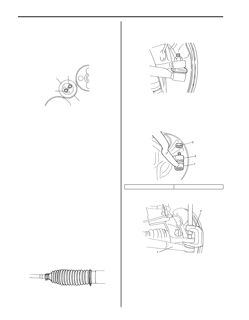
1) Remove tension pulley bolt (1) and nut (2).
2) Remove tension pulley (3) and P/S pump drive belt 

(4).

Installation
Reverse removal procedure noting the following 
instruction.
Adjust belt tension referring to “P/S Pump and A/C 
Compressor (If Equipped) Drive Belt Inspection and 
Adjustment (M16A Engine Model)”
.

P/S Pump and A/C Compressor (If Equipped) 
Drive Belt Removal and Installation (J20A 
Engine Model)

S6JB0A6306008

Refer to “Water Pump and Generator Drive Belt 
Removal and Installation (For J20 Engine): For Petrol 
Engine Model in Section 1J”.

P/S Pump and A/C Compressor (If Equipped) 
Drive Belt Removal and Installation (F9Q Engine 
Model)

S6JB0A6306027

Refer to “Accessory Drive Belt and Idler Pulley Removal 
and Installation: For Diesel Engine Model in Section 1J”.

Steering Rack Boot Check

S6JB0A6306009

• Check boot for crack and damage which, if any, 

means possibility of rusty gear, entry of dust or lack of 
grease. Also, check if any of such faulty conditions 
exists.

• Check steering rack boot for dent or breakage.

If there is a dent, keep boot in most compressed state 
for some seconds to correct dent.

Tie-Rod End Boot Check

S6JB0A6306010

Check boot for crack and damage and if any, replace it 
with a new one.

Tie-Rod End Removal and Installation

S6JB0A6306011

Removal

1) Hoist vehicle and remove wheel.
2) Remove tie-rod end nut (3).

3) Disconnect tie-rod end (1) by using puller (2).

3

4

1

2

I5JB0A630015-01

IYSQ01630013-01

1. Tie-rod end

2. Knuckle

IYSQ01630014-01

IYSQ01630015-01

IYSQ01630016-01

Power Assisted Steering System:  6C-12

4) To facilitate adjustment after installation, put a mark 

(2) on tie-rod thread indicating position of tie-rod end 
lock nut (3). Then loosen lock nut (3) and remove tie-
rod end (4) from tie-rod (1).

Installation

1) Install tie-rod end lock nut (3) and tie-rod end (4) to 

tie-rod (1). Tighten lock nut (3) to mark (2) on tie-rod 
thread.

2) Install tie-rod end (4) to knuckle (5). Tighten new tie-

rod end nut (6) to specified torque.

Tightening torque
Tie-rod end nut (a):  43 N·m (4.3 kgf-m, 31.0 lb-ft)

3) After installing wheels, lower vehicle and tighten 

wheel nuts to specified torque.

Tightening torque
Wheel nut (a):  100 N·m (10.0 kgf-m, 72.5 lb-ft)

4) Check that proper amount of toe-in is obtained 

referring to “Front Wheel Alignment Inspection and 
Adjustment in Section 2B”.

5) After confirming proper amount of toe-in, tighten tie-

rod end lock nut to specified torque.

Tightening torque
Tie-rod end lock nut (a):  65 N·m (6.5 kgf-m, 47.0 
lb-ft)

Tie-Rod End Ball Joint Inspection

S6JB0A6306012

Inspect for play in tie-rod end ball joint (1). If found 
defective, replace.

IYSQ01630017-01

IYSQ01630018-01

IYSQ01630019-01

IYSQ01630020-01

IYSQ01630021-01

6C-13 Power Assisted Steering System: 

P/S Gear Case Assembly Components

S6JB0A6306013

7

8

(b)

8

(b)

6

(d)

6

(d)

4

3

5

5

2

(c)

7

4

3

10

[A]

(a)

10

(a)

9

(e)

1

1

10

(a)

10

(a)

[B]

2

(c)

11

11

11

11

I5JB0A630016-06

[A]: LH steering vehicle

6. Tie-rod end lock nut

: 43 N

⋅m (4.3 kgf-m, 31.0 lb-ft)

[B]: RH steering vehicle

7. Tie-rod end

: 90 N

⋅m (9.0 kgf-m, 65.0 lb-ft)

1. Steering gear case

8. Tie-rod end nut

: 65 N

⋅m (6.5 kgf-m, 47.0 lb-ft)

2. Tie-rod

: Apply thread rock cement 99000-32100 to thread of 
tie-rod boll nut.

9. Steering gear case mounting bolt

: 105 N

⋅m (10.5 kgf-m, 76.0 lb-ft)

3. Band

10. Gear case cylinder pipe

: Do not reuse.

4. Boot

11. Steering gear case mount bushing

5. Rack boot clip

: 25 N

⋅m (2.5 kgf-m, 18.5 lb-ft)

Power Assisted Steering System:  6C-14

P/S Gear Case Assembly Removal and 
Installation

S6JB0A6306014

CAUTION

!


Never disassemble P/S gear case assembly. 
Disassembling will adversely affect original 
performance of P/S gear case assembly.


Removal

1) Disconnect negative (–) cable at battery.
2) Take out P/S fluid in reservoir with syringe or such.
3) Hoist vehicle and remove both right and left wheels.
4) Disconnect both right and left tie-rod ends from 

knuckle referring to Step 2) to 3) of “Removal” in 
“Tie-Rod End Removal and Installation”.

5) (F9Q engine model)

Remove generator referring to “Generator 
Dismounting and Remounting: For Diesel Engine 
Model in Section 1J”.

6) (F9Q engine model)

Remove P/S pump referring to “P/S Pump Removal 
and Installation (F9Q Engine Model)”.

7) (F9Q engine model)

Remove P/S pump bracket (1).

8) Disconnect steering lower shaft assembly (1) from 

pinion shaft of P/S gear case assembly (2) referring 
to Step 5) of “Removal” in “Steering Lower Shaft 
Assembly Removal and Installation in Section 6B”.

9) Disconnect high pressure pipe (3) from P/S gear 

case assembly.

10) Disconnect low pressure pipe (4) from P/S gear case 

assembly.

11) Remove P/S gear case cylinder pipes (5) from P/S 

gear case assembly.

12) Remove stabilizer bar mount bolt and stabilizer joint.

NOTE
Do not remove stabilizer bar from vehicle.


13) Remove stabilizer bar mount bracket (2) from left 

side of front suspension frame.

14) Remove bolts (1) and then take off P/S gear case 

assembly from left side of vehicle.

NOTE
P/S gear case assembly cannot be removed 
from the right side of vehicle.


1

I5JB0B630005-01

1

2

3

5

4

I5JB0A630017-01

1

2

I5JB0A630018-01

1

1

I5JB0A630019-01


Content   ..  365  366  367  368   ..