Renault Zoe (2023 year). Manual in english - page 4

LANE DEPARTURE WARNING (4/4)
This function is an additional driving aid. This function is not under any circumstances intended to replace the due care
and attention of the driver, who should at all times be in control of the vehicle.
System servicing/repairs
- In the event of an impact, the camera alignment may be changed, and its operation may consequently be affected. Deactivate
the function, then consult an authorised dealer.
- Any work in the area where the camera is located (repairs, replacements, windscreen modifications etc.) must be carried
out by a qualified professional.
Only an authorised dealer is qualified to service the system.
In the event of system disturbance
Some conditions can disturb or damage the operation of the system, such as:
- windscreen obscured (by dirt, ice, snow, condensation etc.);
- a complex environment (tunnel etc.);
- poor weather conditions (snow, hail, black ice, rain, etc.);
- poor visibility (night, fog etc.);
- the road markings are irregular or difficult to distinguish (e.g. partially erased, excessive spacing, distorted road surface);
- being dazzled (glaring sun, lights of vehicles travelling in the opposite direction etc.);
- the road is narrow, winding or undulating (tight bends etc.);
- closely following a vehicle travelling in the same lane.
Risk of false alarms or absence of warnings
2.38
CarManuals2.co
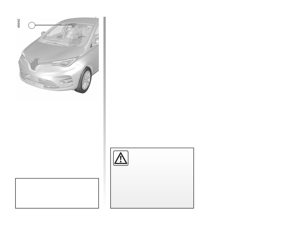
LANE KEEPING ASSIST (1/5)
Note: make sure the windscreen is not
obscured (dirt, mud, snow, condensa-
1
tion etc.).
Using information from the 1 camera,
the function triggers corrective action
on the vehicle steering system when
a continuous or broken line is crossed
or when approaching the roadside (di-
vider, barrier, pavement, embankment,
etc.) without the direction indicator
lights being activated.
This function is an addi-
tional driving aid. This func-
tion is not under any circum-
stances intended to replace
the due care and attention of the
driver, who should at all times be
in control of the vehicle.
You can retake control of the ve-
hicle at any time by operating the
steering wheel.
2.39
CarManuals2.co
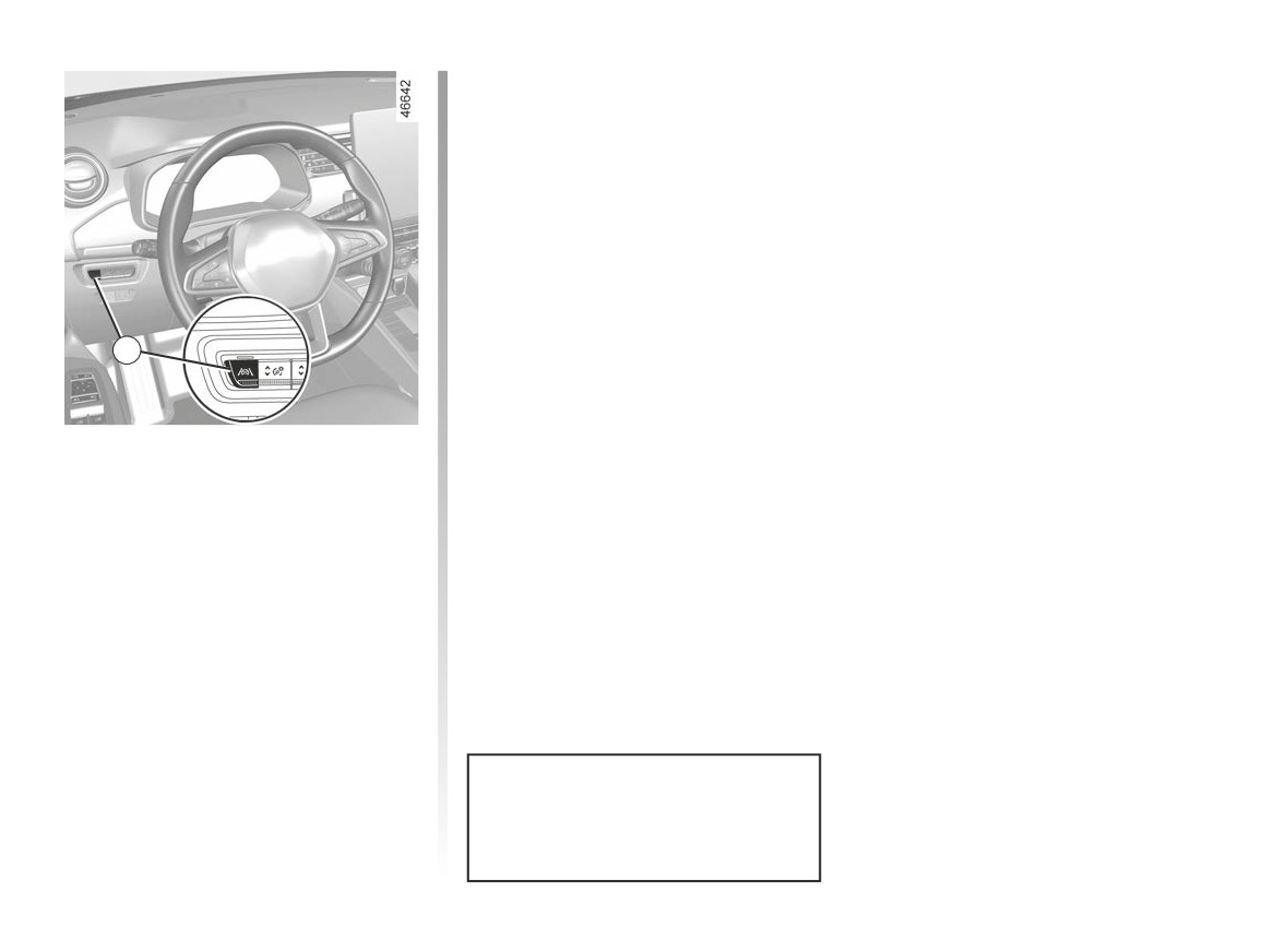
LANE KEEPING ASSIST (2/5)
To disable the function, press the 2
switch as many times as required to
select “Lane Keeping deactivated” on
the instrument panel.
goes out on the in-
Warning light
strument panel.
Note: deactivating the “Lane Keeping
Assist” function causes deactivation of
the “Lane Departure Warning” function.
2
Activation/deactivation
To activate the function, press the 2
switch as many times as required to
select “Lane Keeping Assist” on the in-
strument panel.
The “Lane Keeping activated” message
and “
” warning light are displayed
on the instrument panel.
When Lane Keeping Assist is activated,
the “Lane Departure Warning” function
is automatically activated. ➥ 2.35.
Each time the vehicle is started,
the function continues the mode
saved the last time the engine was
stopped.
2.40
CarManuals2.co
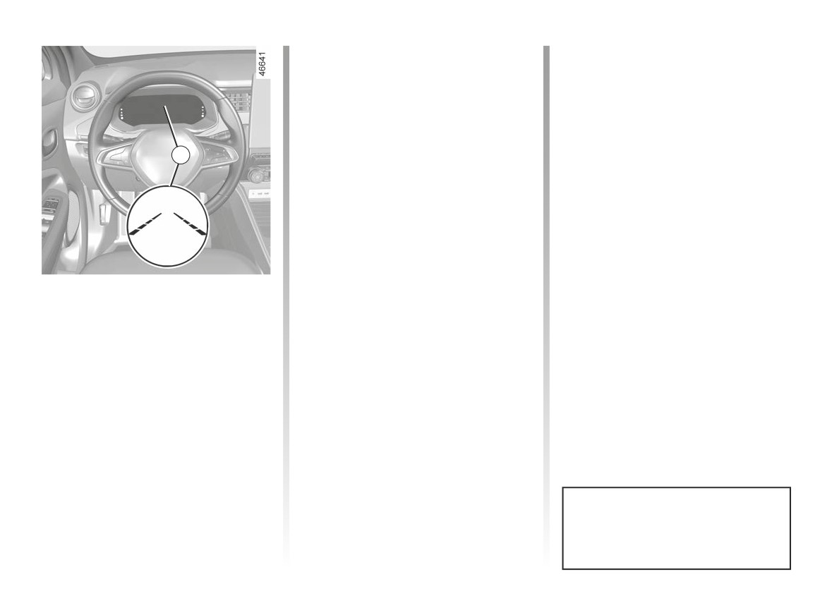
LANE KEEPING ASSIST (3/5)
In these cases:
Special case
– the function triggers an action on the
If the system no longer detects any
vehicle’s steering system to correct
action by the driver on the steering
the vehicle trajectory;
wheel, the
warning light illumi-
nates in yellow on the instrument panel,
- the warning light
and the indi-
accompanied by the message: “Keep
cator 3 on the side of the breached
3
hands on steering wheel” and a beep.
line turns to yellow on the instrument
panel.
The beep sounds together with the
warning light and the message until the
Note: on bends, the function allows for
driver takes control.
slightly cutting the bend.
If the corrective action on the steer-
ing system is not sufficient, the
warning light and 3 indicator on the side
Operation
of the breached line turn to red on the
When the function is activated, the
instrument panel, accompanied by a vi-
bration on the steering wheel.
warning light and the left and
right lines 3 are displayed in grey on the
instrument panel.
The function is set to operate when
the vehicle speed is between approxi-
mately 43 mph (70 km/h) and 112 mph
(180 km/h) and if the
warning
light and 3 correction indicators are col-
oured white.
The function operates if the vehicle
breaches a line or if the vehicle ap-
proaches the roadside (divider, barrier,
You can interrupt the trajectory cor-
pavement, embankment, etc.) without
rection at any time by moving the
the direction indicator lights being ac-
steering wheel.
tivated.
2.41
CarManuals2.co
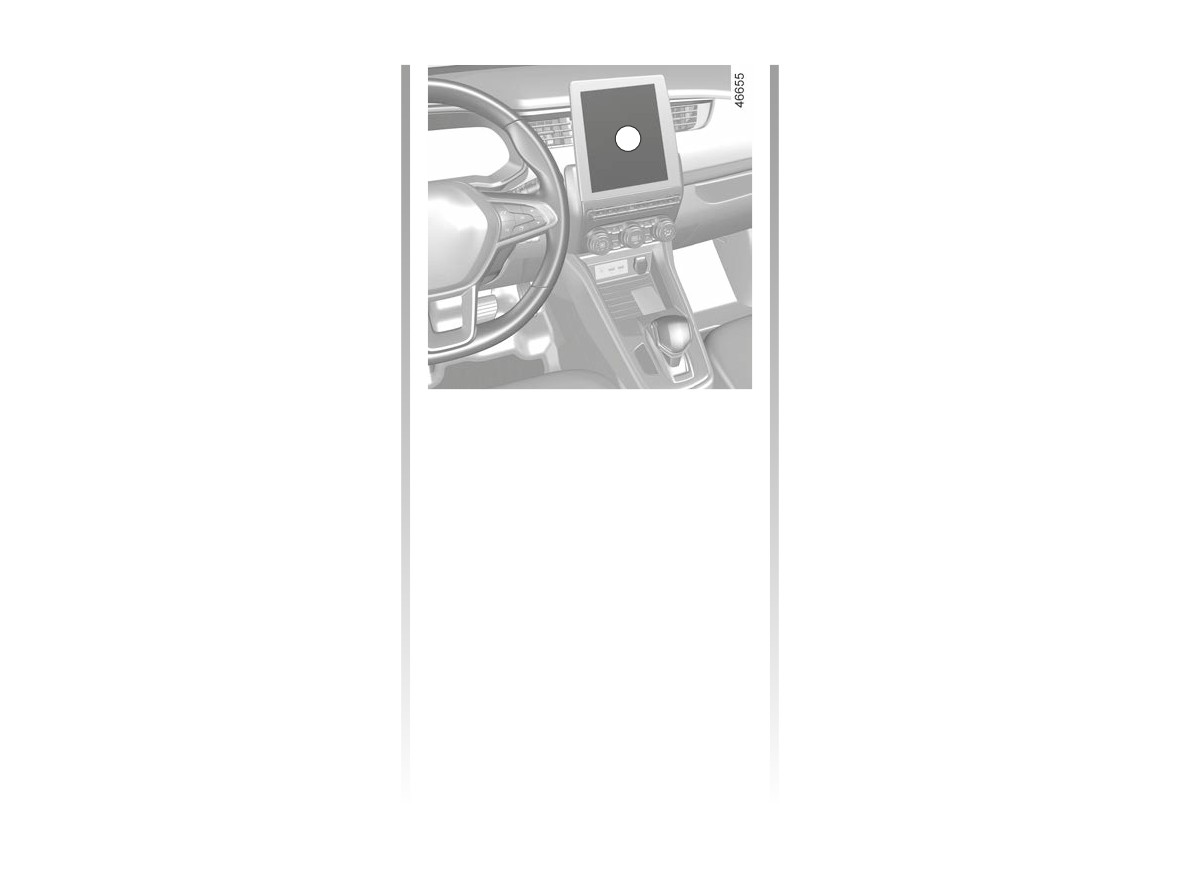
LANE KEEPING ASSIST (4/5)
Temporarily not available
Adjustment
With the vehicle stationary, engine run-
- Very fast lane departure;
ning, from the multimedia screen 4
- driving continuously on a line;
4
select the “Settings” menu, “Vehicle”
tab, the
“Driving assistance” menu,
- four seconds approximately after
then “Lane”:
changing lanes;
- “Vibration”: adjust steering wheel
- tight bends;
vibration for the
“Lane Departure
- impaired visibility;
Warning” function;
- “Alert”: adjust the sensitivity level for
- activation of one of the direction indi-
line detection. To do this, select:
cator lights;
- “Late”: line detected when cross-
- strong acceleration;
ing;
- “Standard”: line detected on ap-
- emergency braking;
proach;
- ...
- “Early”: line detected nearby.
Conditions for non-activation
Please refer to the multimedia instruc-
If the function is unavailable, the
of the system
tions for further information.
warning light and the left/right correc-
The system cannot be activated when:
tion warning lights 3 appear in grey on
- reverse gear is engaged;
the instrument panel.
Operating faults
- the field of vision of the camera is ob-
structed;
When the system detects an operating
- the® warning light is displayed.
fault, the
warning light lights up
on the instrument panel, with the mes-
The
warning light and the left/
sage “Front camera to check”.
right line warning lights are displayed in
Consult an approved dealer.
grey on the instrument panel.
2.42
CarManuals2.co

LANE KEEPING ASSIST (5/5)
This function is an additional driving aid. This function is not under any circumstances intended to replace the due care
and attention of the driver, who should at all times be in control of the vehicle.
System servicing/repairs
- In the event of an impact, the camera alignment may be changed, and its operation may consequently be affected. Deactivate
the function and consult an authorised dealer.
- Any work in the area where the camera is located (repairs, replacements, windscreen modifications etc.) must be carried
out by a qualified professional.
Only an authorised dealer is qualified to service the system.
In the event of system disturbance
Some conditions can disturb or damage the operation of the system, such as:
- windscreen obscured (by dirt, ice, snow, condensation etc.);
- a complex environment (tunnel etc.);
- poor weather conditions (snow, hail, black ice, rain, etc.);
- poor visibility (night, fog etc.);
- the road markings are irregular or difficult to distinguish (e.g. partially erased, excessive spacing, distorted road surface);
- being dazzled (glaring sun, lights of vehicles travelling in the opposite direction etc.);
- the road is narrow, winding or undulating (tight bends etc.);
- closely following a vehicle travelling in the same lane.
In this case, the “Lane Keeping Assist” may react incorrectly or not at all.
Risk of unwanted, incorrect correction or no correction of trajectory.
Deactivating the function
You must disable the function if:
- the area of the camera has been damaged (on the windscreen side or the interior rear-view mirror side);
- the road is slippery (snow, black ice, aquaplaning, gravel etc.) ;
- poor visibility (night, fog etc.);
- the windscreen is cracked or distorted (do not carry out windscreen repairs in this area; have it changed by an Authorised
Dealer);
- the vehicle is towing a trailer or a caravan;
- the vehicle is entering an area with several surface markings (an area with road works etc.).
2.43
CarManuals2.co
BLIND SPOT WARNING (1/5)
1
A
A
This function is an addi-
tional aid which indicates
other vehicles in the blind
spot area.
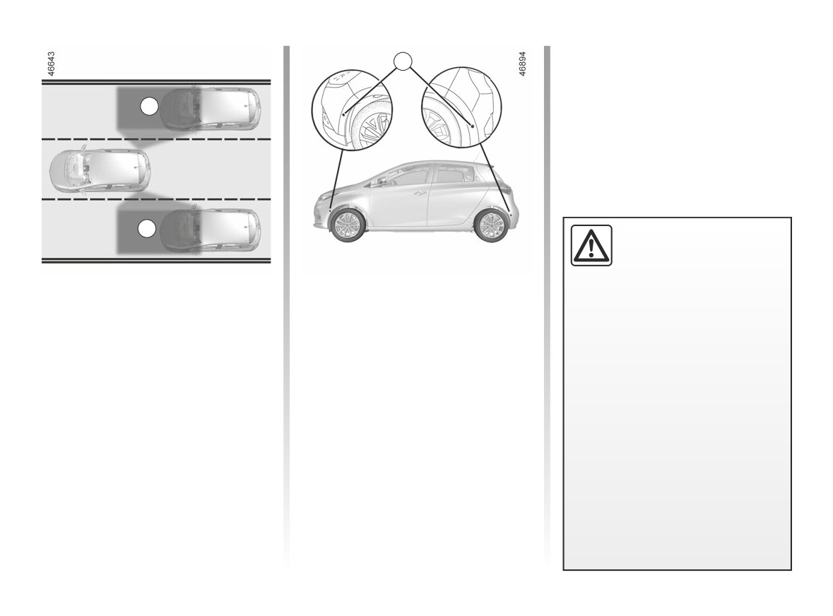
This system alerts the driver to other
Special feature
It can never in any case be a sub-
vehicles in the detection zone A.
Make sure that the sensors are not ob-
stitute for care nor for the driver’s
The system is activated when the ve-
scured (by dirt, mud, snow, etc.).
responsibility while in charge of his
hicle’s speed is between approximately
If a sensor is obscured, the message
vehicle.
19 mph
(30 km/h) and
87 mph
“Blind spotclean sensor” will appear on
The driver should always be ready
(140 km/h).
the instrument panel. Clean the sen-
for sudden incidents while driv-
This function uses sensors 1 installed in
sors.
ing: always ensure that there are
the front and rear bumper of both sides.
no moving obstacles (such as a
child, animal, pushchair or bicy-
cle) or small, narrow objects such
as stones or posts in the blind spot
when manoeuvring.
2.44
CarManuals2.co
BLIND SPOT WARNING (2/5)
3
B
2
3
4
C
D
Activation/deactivation
Indicator 3
Operation
Vehicle stationary, engine running, from
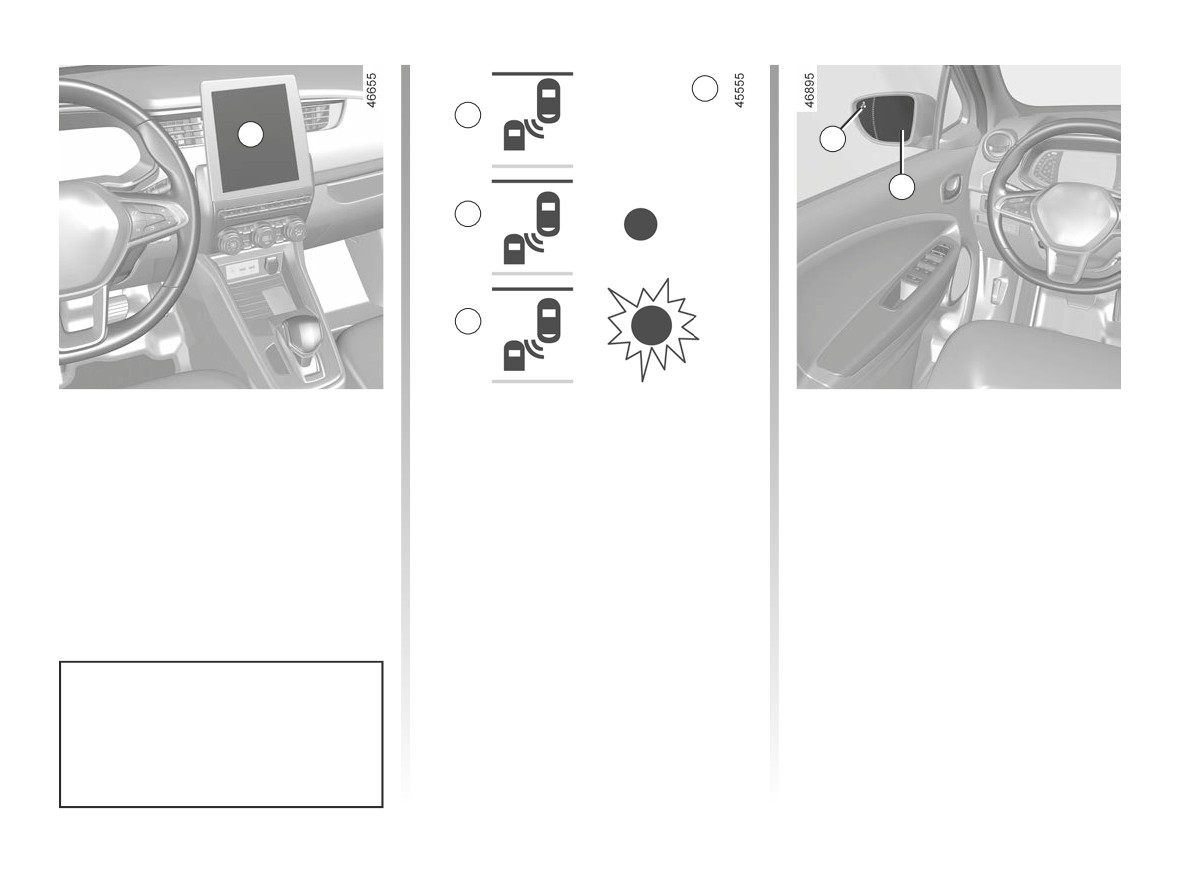
An indicator light 3 is located on each
This function gives a warning:
the multimedia screen 2, select the
rear view mirror 4.
- when the vehicle speed is between
“Settings” menu, “Vehicle” tab, select
Note: clean the rear view mirrors 4 reg-
approximately 19 mph (30 km/h) and
the “Driving assistance” menu, “Blind
ularly so that the indicators 3 can be
87 mph (140 km/h);
spot alert”, then select ON or OFF.
seen.
- when another vehicle is in the blind
spot area and travelling in the same
direction as your vehicle.
If another vehicle is being overtaken,
the indicator 3 will be activated only if
that vehicle remains in the blind spot for
more than one second.
The system’s detection range oper-
ates according to a standard lane
width. If you are driving in narrow
traffic lanes, it may detect vehicles
in other lanes.
2.45
CarManuals2.co
BLIND SPOT WARNING (3/5)
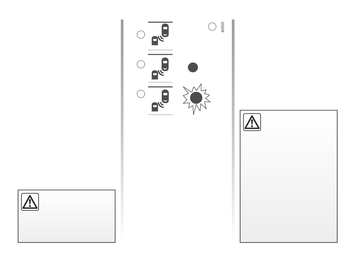
Display B
Operating faults
3
The function is activated and has not
If the system detects a fault, the mes-
B
detected any vehicles.
sage “Check blind spot alert” is dis-
played on the instrument panel. Call an
approved Dealer.
Display C
First warning: the indicator 3 means
C
that a vehicle has been detected in the
blind spot.
Display D
D
When the direction indicator is acti-
vated, the indicator light 3 flashes when
a vehicle is detected in the blind spot on
The system’s detection
the side towards which you are about to
Conditions for non-function
range operates according
steer. If you cancel the direction indica-
to a standard lane width. If
tor, the function will return to the initial
- If the object is not moving;
you are driving in wide traf-
warning (display C).
- if traffic is heavy;
fic lanes, the system might not be
- the road is winding;
able to detect a vehicle in the blind
spot.
- if front and rear sensors both detect
an object at the same time (e.g.
The system might be disrupted mo-
when passing an articulated lorry).
mentarily if it is exposed to strong
electromagnetic waves (as beneath
– ...
high-tension power lines) or to very
poor weather conditions
(heavy
rain, snow etc.). Remain aware of
Because sensors have
driving conditions.
been installed in the bump-
ers, any work (repairs, re-
There is a risk of accidents.
placements, touching up of
paintwork) must be carried out by a
qualified professional.
2.46
CarManuals2.co

BLIND SPOT WARNING (4/5)
This function is an additional driving aid. This function is not under any circumstances intended to replace the due care
and attention of the driver, who should at all times be in control of the vehicle.
The driver should always adapt their speed to the traffic conditions, regardless of the system indications.
The system should under no circumstances be taken to be an obstacle detector or an anti-collision system.
System servicing/repairs
- In the event of an impact, the alignment of the sensors may be changed and its operation may consequently be affected.
Deactivate the function and consult an authorised dealer.
- Any work in the area where the sensors are located (repairs, replacements, etc.) must be carried out by a qualified profes-
sional.
Only an authorised dealer is qualified to service the system.
System disturbance
Some conditions can disturb or damage the operation of the system, such as:
- complex surroundings (metal bridges, tunnels, roads with barriers at the edge, etc.);
- poor weather conditions (snow, hail, black ice, etc.).
Risk of false alarms or absence of warnings
In the event of the system behaving abnormally, deactivate it and consult an authorised dealer.
2.47
CarManuals2.co

BLIND SPOT WARNING (5/5)
Limitation of the system operation
- The sensors must be kept clean and free of modifications in order for the system to operate correctly.
- Small objects moving close to the vehicle (motorcycles, bicycles, pedestrians, etc.) may not be recognised by the
system.
- When the vehicle enters corners and curves, the system may temporarily cease to detect vehicles in adjacent lanes.
- The system may not react when there is a significant difference in speed with other vehicles.
- If the vehicle is being overtaken by a long vehicle (e.g. heavy goods vehicle overtaking at a similar speed to the vehicle) the
system may interrupt the warning before the end of the manoeuvre.
- The vehicle is travelling on a winding road.
Deactivating the function
You must disable the function if the sensors have been damaged (rear bumper).
2.48
CarManuals2.co
DETECTION OF ROAD SIGNS (1/4)
Note: make sure the windscreen is not
For vehicles equipped with a navigation
1
obscured (dirt, mud, snow, condensa-
system and if the vehicle is travelling in
tion etc.).
a country where the speed units differ
from those of the vehicle, the system
For vehicles which are equipped with it,
displays the speed limit sign in the unit
the system also uses information from
of the country, alongside the speed limit
the navigation system.
converted to the unit used by the vehi-
Once the speed limiter is activated, you
cle’s instrument panel.
can adjust the speed limiter indication
For countries where the speed limit is
displayed by the system.
reduced during rainy weather on some
If the limit speed is exceeded, the dis-
types of roads, on vehicles equipped
play panel is modified to warn the driver.
with a navigation system, the system
can modify the limited speed after a few
seconds of wiping the windscreen.
Special situations
The system detects speed limit signs
The system does not take into account
on the side of the road and displays the
exceptional speed limit measures, such
speed limit on the instrument panel.
as peak pollution days.
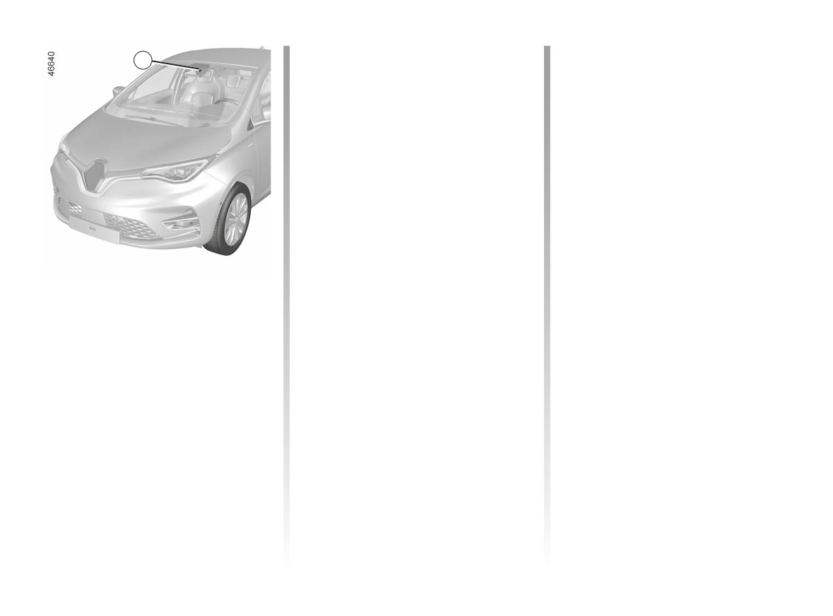
It mainly uses information taken from
the camera 1, attached to the wind-
screen behind the rear view mirror.
2.49
CarManuals2.co
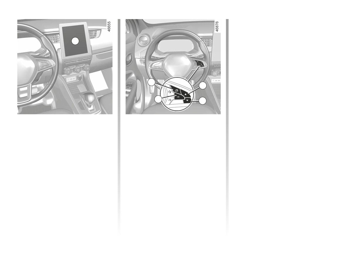
DETECTION OF ROAD SIGNS (2/4)
- press the 4 or 5 control repeatedly to
reach the “Settings” menu. Press the
switch 6 OK;
- press the 4 or 5 control repeatedly to
2
reach the “DRIVING ASSIST” menu.
Press the switch 6 OK;
- press the 4 or 5 control repeatedly
to reach the “Speed alert” menu and
press the 6 OK switch;
- press the 6 OK switch to activate or
3
deactivate the function:
4
=
function activated
6
5
function deactivated
<
Activating/deactivating the
With the function activated, depend-
ing on local regulations, you can acti-
system
vate the “Risk area display” option. The
Vehicles fitted with a multimedia
system will notify you of the distance
screen.
separating you from this zone, and
while you are travelling in the zone.
Vehicle stationary, engine running,
from the multimedia screen 2 select
Vehicles not fitted with a multimedia
the “Settings” menu, “Vehicle” tab, the
screen
“Driving assistance” menu,
“Traffic
- With the vehicle stationary, press
signs”, then select “ON” or “OFF”.
switch 3, as many times as required
to reach the “Vehicle” tab;
2.50
CarManuals2.co
DETECTION OF ROAD SIGNS (3/4)
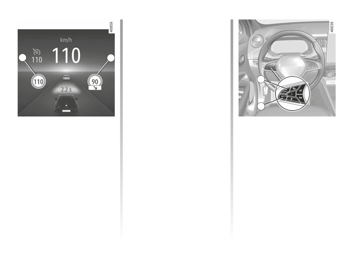
If the speed limit is exceeded, the circle
around the panel flashes (7 warning
light) along with a sound signal to warn
the driver.
7
8
9
10
Operation
Varying the limit speed
If the speed limit notification differs from
Warning lights
the detected speed value, press and
The function displays the following
hold the following switches:
warning lights:
- 9 (RES/+) to increase the notification
7 Speed limit road signs
speed to the detected speed;
8 Additional road signs (start or end
- 10 (SET/-) to reduce the notification
of “No overtaking” zone, slip road
speed to the detected speed.
speed limit, speed in case of a cara-
van, speed limit with length of appli-
cation, etc.)
2.51
CarManuals2.co

DETECTION OF ROAD SIGNS (4/4)
Operating faults
The system cannot detect the speed
limit if:
- the windscreen is not clean;
- the camera is blinded by the sun;
- there is insufficient visibility (night,
fog etc.);
- the signs are not legible (snow, etc.)
or are hidden (by another vehicle or
by trees);
- the information taken from the navi-
gation system is not up to date.
This function is an additional driving aid. This function is not under any
circumstances intended to replace the due care and attention of the
driver, who should at all times be in control of the vehicle.
The driver should always adapt their speed to the traffic conditions, re-
gardless of the system indications.
The system detects speed limit signs and does not detect other signs (e.g. entry/
exit to/from urban areas, etc.).
The system may not detect all speed limit signs or may interpret them incorrectly.
The driver should not ignore signs that are not detected by the system and should,
as a priority, comply with the traffic signage and the highway code.
In the event of poor visibility (fog, snow, frost, etc.), it is possible that the system
may not indicate the correct speed to the driver.
The driver should always adapt their speed to the traffic conditions, regardless of
the system indications.
2.52
CarManuals2.co
SPEED LIMITER (1/4)
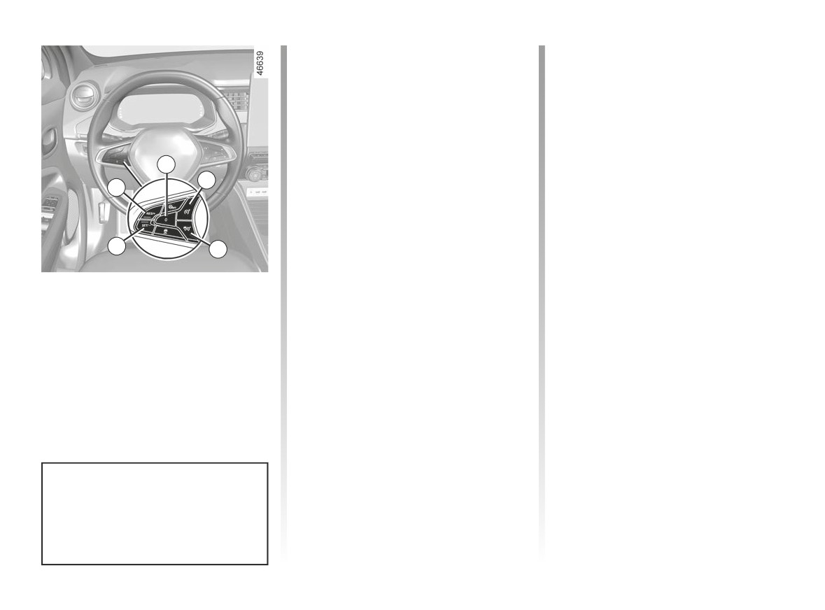
Controls
Driving
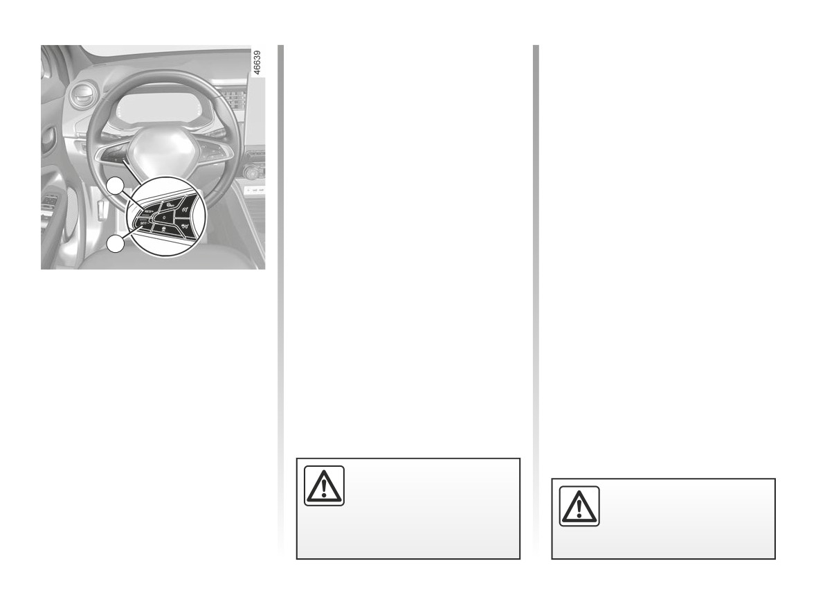
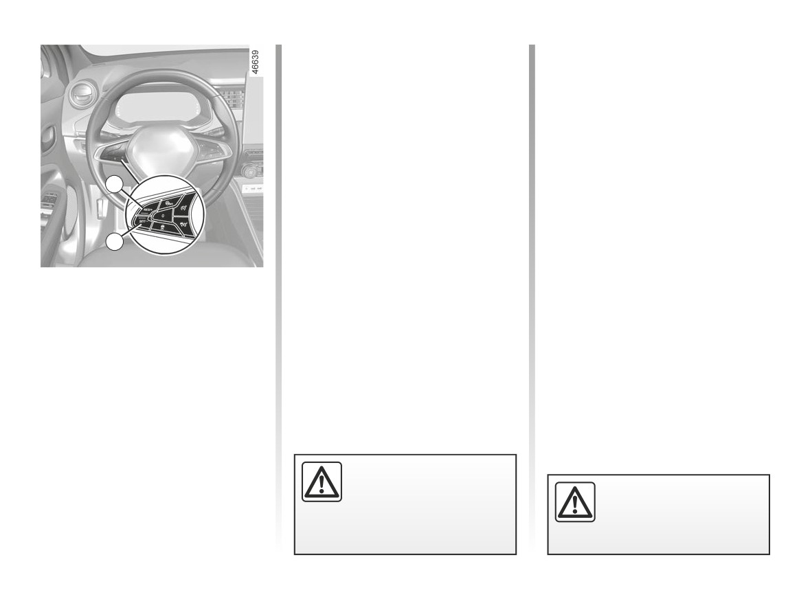
1 Speed limiter On/Off switch.
When a limit speed has been set but
not yet reached, driving is similar to
2 Cruise control On/Off switch.
driving a vehicle without the speed lim-
3 Switch to activate and decrease the
iter function.
limit speed (SET/-).
Once you have reached the stored
4 Switch to activate and increase the
speed, no effort on the accelera-
5
limit speed or to set the stored limit
tor pedal will allow you to exceed
1
speed (RES/+).
the programmed speed except in an
4
5 Speed limiter function standby (with
emergency (refer to information on
limited speed memory) (0).
“Exceeding the limit speed”).
3
2
The speed limiter function helps you
stay within the driving speed limit that
you choose, known as the limit speed.
You can link the speed limiter to
the “Road sign detection” function.
➥ 2.49.
2.53
CarManuals2.co
SPEED LIMITER (2/4)
6
1
4
3
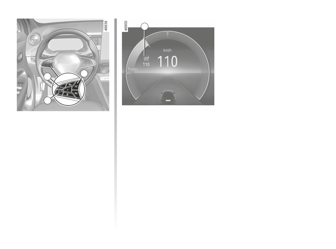
Switching on
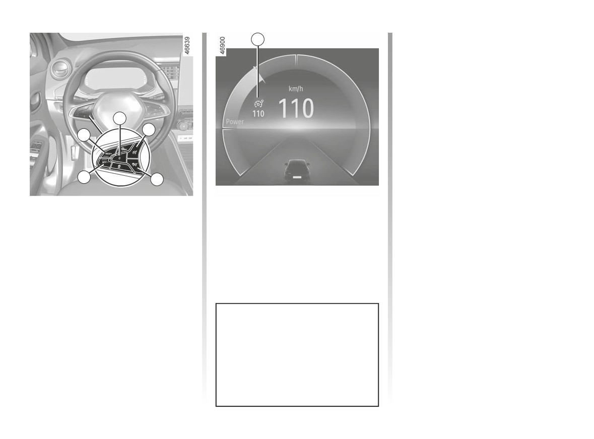
To store the current speed, press the 4
switch (RES/+) or the 3 switch (SET/- ):
Press switch 1. The 6 warning light ap-
the limit speed replaces the dashes
pears in grey. The “Speed limiter ON”
and, depending on the vehicle, the 6
message appears on the instrument
warning light appears in white.
panel accompanied by dashes to indi-
The minimum stored speed is 20 mph
cate that the speed limiter function is in
(30 km/h).
operation, waiting to store a limit speed.
2.54
CarManuals2.co
SPEED LIMITER (3/4)
Exceeding the limit speed
Limited speed cannot be maintained
It is possible to exceed the limit speed
When driving down a steep gradient,
at any time. To do this: press the accel-
the system may not maintain the limit
erator pedal firmly and fully (beyond
speed: the limit speed flashes in red
the resistance point).
on the instrument panel and an audi-
ble signal sounds at regular intervals to
While the speed is being exceeded, the
inform you of this situation.
speed limiter flashes red on the instru-
ment panel. Then, release the accelera-
tor pedal: the speed limiter function will
4
return as soon as you reach a speed
lower than the memorised speed.
3
Varying the limit speed
The limit speed may be changed by
pressing repeatedly or holding down:
- switch 4 (RES/+) to increase speed;
- switch 3 (SET/-) to reduce speed.
If the speed limiter is not
available (after several at-
The speed limiter function is
tempts to activate), contact
in no way linked to the brak-
an approved dealer.
ing system.
2.55
CarManuals2.co
SPEED LIMITER (4/4)
6
Switching off the function
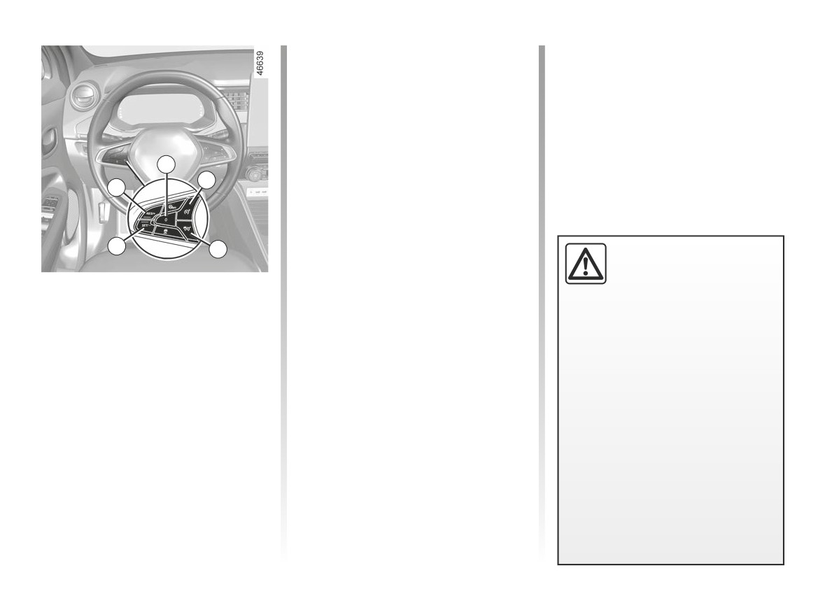
The speed limiter function is inter-
rupted:
- when you press the 1 switch. In this
case, the speed is no longer stored;
- when you press the 2 switch. In this
case the cruise control is selected
5
and there is no stored speed.
1
4
The warning light 6 disappears from
the instrument panel to confirm that the
function is no longer active.
3
2
Putting the function on
standby
The speed limiter function is suspended
when you press switch 5 (0). The limit
speed is stored and displayed in grey
on the instrument panel.
Recalling the limit speed
If a speed has been stored, it can be re-
called by pressing the 4 switch.
When the speed limiter is set to
standby, pressing the 3 switch re-
activates the function without taking
into account the memorised speed:
the speed at which the vehicle is
moving is taken into account.
2.56
CarManuals2.co
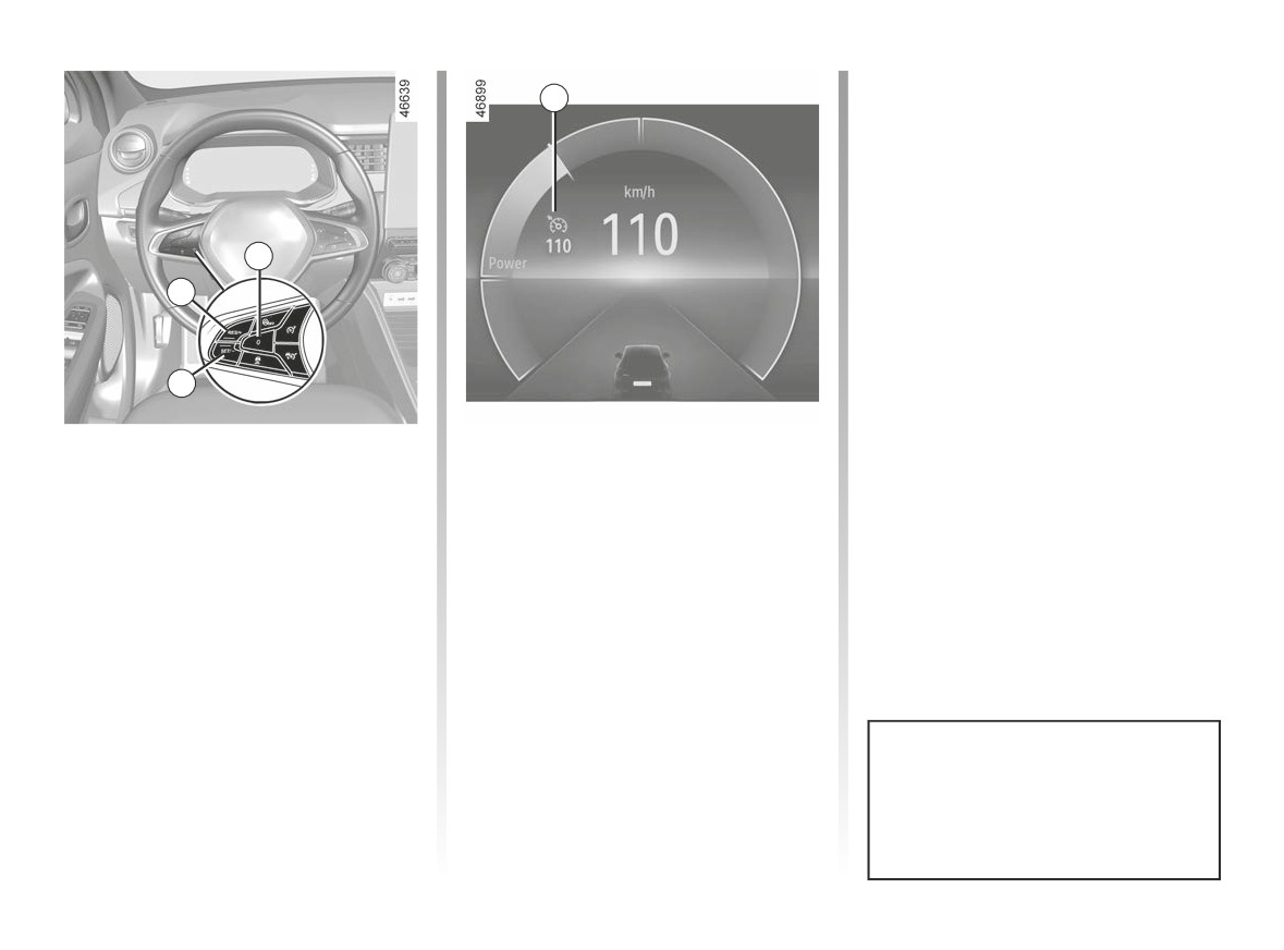
CRUISE CONTROL (1/5)
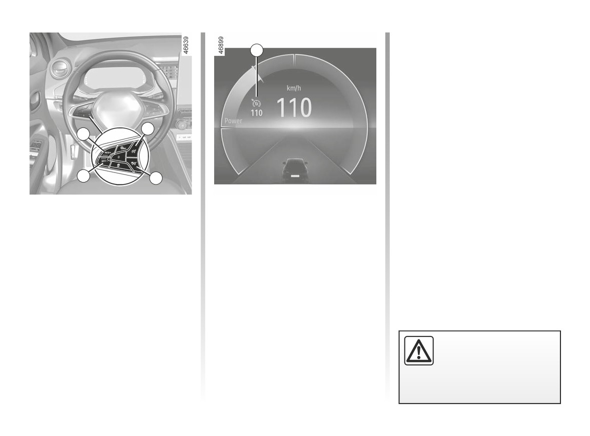
Controls
1 Cruise control On/Off switch.
2 Switch to activate and decrease
cruising speed (SET/-).
3 Switch to activate and increase
cruising speed or to recall the mem-
orised cruising speed (RES/+).
4
5
4 Switch the function to standby (with
3
cruising speed saved) (0).
5 Speed limiter On/Off switch.
2
1
This function is an addi-
tional driving aid.
The cruise control function helps you to
It can under no circum-
maintain your driving speed at a speed
stances replace the driver’s
that you choose, called the cruising
responsibility to respect speed limits
speed.
or to be vigilant. The driver must
always be in control of the vehicle.
This cruising speed may be set at any
speed above 19 mph (30 km/h).
Cruise control must not be used
in heavy traffic, on winding or slip-
pery roads (black ice, aquaplan-
ing, gravel) and during bad weather
(fog, rain, side winds etc.).
There is a risk of accidents.
2.57
CarManuals2.co
CRUISE CONTROL (2/5)
Driving
6
Once a cruising speed is registered
and the cruise control function is active,
you may lift your foot off the accelera-
tor pedal.
5
3
2
1
Switching on
Activating cruise control
Press switch 1.
At a steady speed above approximately
19 mph (30 km/h), press the 2 (SET/-)
The 6 warning light appears in grey.
switch or the 3 (RES/+) switch : the
The “Cruise control ON” message ap-
function is activated and the current
pears on the instrument panel accom-
speed is taken into account.
panied by dashes to indicate that the
The cruising speed replaces the
cruise control function is in operation
dashes. Cruise control is confirmed
and waiting to memorise a cruising
when the memorised speed and warn-
speed.
ing light appear in green 6.
If you try to activate the function below
19 mph (30 km/h), the message “Invalid
Speed” will be displayed and the func-
Please note that you must
tion will remain inactive.
keep your foot close to the
pedals in order to react in
an emergency.
2.58
CarManuals2.co
CRUISE CONTROL (3/5)
Exceeding the cruising speed
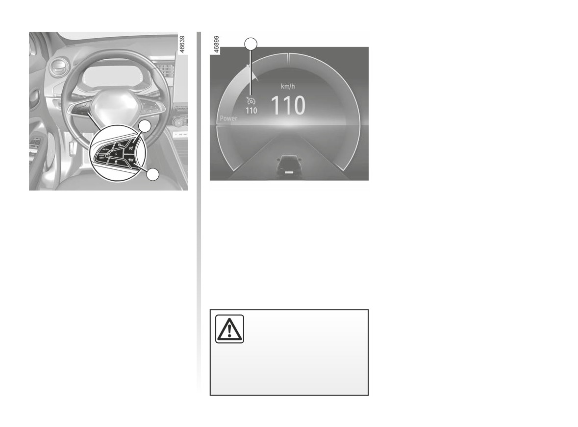
The cruising speed may be exceeded
at any time by depressing the accelera-
tor pedal.
While it is being exceeded, the cruising
speed flashes on the instrument panel.
Then, release the accelerator pedal:
after a few seconds, the vehicle will
3
automatically return to its set cruising
speed.
Cruising speed cannot be
maintained
2
When driving down a steep gradient,
the system is unable to maintain the
Adjusting the cruising speed
cruising speed: the stored speed will
The cruising speed may be changed by
flash on the instrument panel informa-
pressing the following repeatedly:
tion display to inform you of this situ-
ation.
- the 2 switch (SET/-) to reduce the
speed;
- the 3 switch (RES/+) to increase the
speed.
Note: press and hold one of the
switches to modify speed by succes-
sive increments.
If the cruise control is no
longer available (after sev-
The cruise control function
eral attempts to activate it),
is in no way linked to the
contact an approved dealer.
braking system.
2.59
CarManuals2.co
CRUISE CONTROL (4/5)
NB: if the speed previously stored is
6
much higher than the current speed,
the vehicle will accelerate more rapidly
to reach this threshold.
When the cruise control is set to
standby, pressing switch 2 (SET/-) re-
activates the cruise control function
without taking into account the stored
4
speed: it is the speed at which the vehi-
3
cle is moving that is taken into account.
2
Putting the function on
Returning to the cruising speed
standby
If a speed is stored, it can be recalled,
once you are sure that the road condi-
The function is set to standby if you:
tions are suitable (traffic, road surface,
- 4 switch (0);
weather conditions, etc.). Press the
- the brake pedal;
switch 3 (RES/+) if the vehicle speed is
above 19 mph (30 km/h).
- move to the neutral position.
When the speed is stored, cruise con-
The cruising speed is stored and dis-
trol activation s confirmed by display of
played in grey on the instrument panel.
the cruising speed and, depending on
the vehicle, the 6 warning light is dis-
played.
Cruise control switches to standby
each time ECO mode is activated or
deactivated ➥ 2.13.
2.60
CarManuals2.co
CRUISE CONTROL (5/5)
6
5
1
Switching off the function
The warning light 6 disappears from
the instrument panel to confirm that the
The cruise control function is inter-
function is no longer active.
rupted:
- when you press the 1 switch. In this
case, the speed is no longer stored;
- when you press the 5 switch. In this
case the speed limiter is selected
and there is no stored speed.
Putting the cruise control
on standby or switching it
off does not cause a rapid
reduction in speed: you
must brake by depressing the brake
pedal.
2.61
CarManuals2.co
“AUTOHOLD” FUNCTION
Vehicle stopped (e.g. at a red light, an
Conditions for interrupting the
intersection, a traffic jam, etc.), the func-
braking force
tion ensures braking force even when
The following conditions must be met:
the driver releases the brake pedal.
- the driver accelerates sufficiently
The braking force is released as soon
with a gear engaged;
as the driver accelerates sufficiently
or
with a gear engaged.
- the driver disables the function.
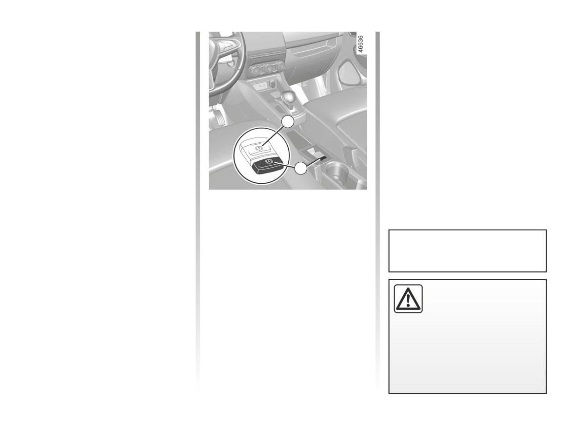
Activation
1
Warning light
goes out on the in-
strument panel.
Press switch 2.
The switch warning light 2 illuminates
to confirm that the function is activated.
2
Deactivation
Press the brake pedal and 2 switch si-
Conditions for maintaining the
multaneously.
braking force
The switch warning light 2 turns off,
The following conditions must be met:
confirming that the function is deacti-
- the seat belt for the driver is fas-
vated.
tened;
Upon each start-up, the function
If the braking force is maintained, the
and
continues the mode set at the time
parking brake is applied automatically
- the electronic parking brake is re-
the engine was last switched off.
when:
leased;
- the driver exits the vehicle;
and
or
Before leaving the vehicle,
- the vehicle is not stationary on a very
- the vehicle is immobilised for more
check that the electronic
steep slope.
than approximately three minutes.
parking brake is fully ap-
The maintained braking force is con-
plied. The indicator light on
firmed by the
warning light on
switch 1 and the warning light }
the instrument panel.
on the instrument panel illuminate to
show that the parking brake is ap-
plied and switch off when the doors
are locked.
2.62
CarManuals2.co
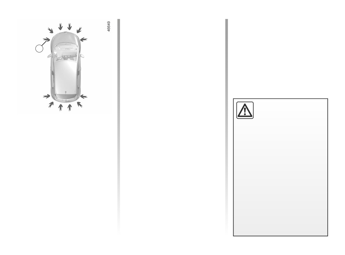
PARKING DISTANCE CONTROL (1/7)
Depending on the vehicle, the system
detects obstacles to the front, the rear
and the sides of the vehicle.
The parking distance control system
1
is only activated when the vehicle is
driven at a speed below approximately
6 mph (10 km/h).
This measurement is indicated by
beeps which become more frequent the
closer you come to the obstacle, until
they become a continuous beep when
the vehicle is approximately
20 to
30 centimetres from the obstacle.
This function is an
addi-
tional driving aid.
Location of the ultrasonic
Operating principle
Under no circumstances
sensors 1
should it replace the driv-
Ultrasonic sensors, indicated
by
Ensure that the ultrasonic sensors indi-
er’s care or responsibility whilst re-
arrows 1, are fitted in the bumpers to
cated by the arrows 1 are not obscured
versing.
measure the distance between the ve-
(by dirt, mud, snow, a badly fitted/at-
hicle and an obstacle.
The driver should always be ready
tached number plate, etc.), impacted,
for sudden incidents while driv-
modified (including paintwork) or ob-
ing: always ensure that there are
structed by any accessory fitted to the
no small, narrow moving obstacles
rear and/or, depending on the vehicle,
(such as a child, animal, pushchair,
to the front or sides of your vehicle.
bicycle, stone, post, etc.) in the blind
spot when manoeuvring.
2.63
CarManuals2.co
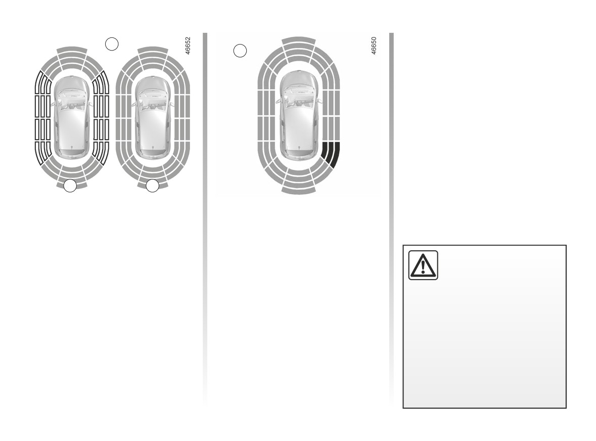
PARKING DISTANCE CONTROL (2/7)
Note: in the event of a change in tra-
2
jectory during a manoeuvre, the risk of
C
collision with an obstacles may be sig-
nalled late.
A
B
Vehicle fitted with a navigation
Operation
system
Most objects located less near the
Note: the display 2 shows the vehicle
front, rear and sides of the vehicle are
surroundings and emits beeps.
detected.
It is necessary to travel a few metres
Depending on the distance of the ob-
An impact to the under-
before the side detection is activated.
stacle, the frequency of the beep will
side of the vehicle while
If all areas have a grey background, the
be higher while approaching it, and
manoeuvring
(e.g. strik-
whole area around the vehicle is being
will become a continuous beep around
ing a post, raised kerb or
monitored:
20 cm away for obstacles to the sides,
other street furniture) may result in
- A: analysis of the vehicle surround-
and around 30 cm for obstacles to the
damage to the vehicle (e.g. defor-
ings in progress;
front or rear. Depending on the vehicle,
mation of an axle).
- B: analysis of the vehicle surround-
the green, orange (or yellow depending
To avoid any risk of accident, have
ings carried out.
on the vehicle) and red zones will be
your vehicle checked by an ap-
displayed on the C display.
proved dealer.
2.64
CarManuals2.co
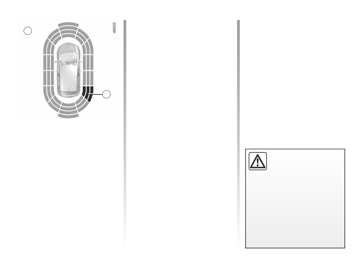
PARKING DISTANCE CONTROL (3/7)
If a side obstacle is detected:
D
- the beeps become faster and then
sound continuously as the obstacle
gets nearer. Green, orange and red
zones will be displayed on the dis-
play D;
- if there is no risk of collision, no beep
will sound when approaching the ob-
stacle. Green, orange and red zones
will be displayed interspersed on the
display D.
3
Note: in the event of a change in tra-
jectory during a manoeuvre, the risk of
collision with an obstacle may be sig-
nalled late.
Detection of obstacles to the side
(depending on the vehicle)
Depending on the direction of the
wheels, the system determines the tra-
jectory of the vehicle and notifies the
An impact
to the under-
driver of any risk or otherwise of a col-
side of the vehicle while
lision with an obstacle 3 to the side of
manoeuvring
(e.g. strik-
the vehicle.
ing a post, raised kerb or
other street furniture) may result in
damage to the vehicle (e.g. defor-
mation of an axle).
To avoid any risk of accident, have
your vehicle checked by an ap-
proved Dealer.
2.65
CarManuals2.co
PARKING DISTANCE CONTROL (4/7)
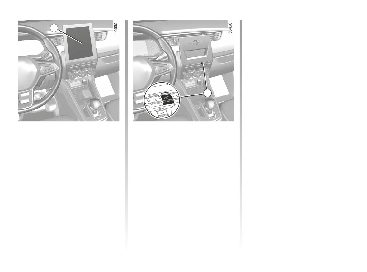
Setting on vehicles not fitted
4
with a navigation system
Depending on the vehicle, with the ve-
hicle stationary, engine running, some
settings can be adjusted from the multi-
media screen 4.
Please refer to the multimedia instruc-
tions for further information.
Select “Settings”, “Parking assistance”.
5
Parking distance control audio
volume
Select “Settings”, “Parking assistance”,
“Sound”. Adjust the volume of Park
Assist by pressing “+” or “-”.
Activation/deactivation
Vehicles without a navigation
system
Vehicle fitted with a navigation
With the vehicle stationary and the
system
engine running, press switch 5 to acti-
With the vehicle stationary and the
vate or deactivate the function.
engine running, from the multimedia
screen 4, select the “Settings” menu,
select the
“Vehicle” tab, select the
“Parking assistance” menu then select
“ON” or “OFF” to activate or deactivate
areas covered by the ultrasonic sen-
sors.
2.66
CarManuals2.co

PARKING DISTANCE CONTROL (5/7)
Setting on vehicles fitted
Parking distance control
Operating faults
with a navigation system
automatic deactivation
If the system detects an operating fault,
(continued)
The system deactivates:
a beep sounds for approximately three
seconds each time the reverse gear is
System sound
- when the vehicle speed is above ap-
selected and the message “Check park-
proximately 6 mph (10 km/h);
ing distance control” appears on the in-
Enables the system sound to be
- depending on the model, when the
strument panel. Check that your ultra-
chosen. Select “Settings”, “Parking as-
vehicle is stationary for more than
sonic sensors are clean. If the message
sistance”, “Sound”.
approximately 5 seconds and an ob-
remains, contact an approved dealer.
Deactivating the system sound
stacle is detected (such as when in a
traffic jam, etc.);
Activate or deactivate the parking dis-
tance control sound.
- when you are in position N;
Note: if you deactivate the sound, you
- when an operating fault is detected.
will no longer be notified with beeps
when approaching an obstacle.
An impact to the under-
side of the vehicle while
manoeuvring
(e.g. strik-
ing a post, raised kerb or
other street furniture) may result in
damage to the vehicle (e.g. defor-
mation of an axle).
To avoid any risk of accident, have
When the vehicle is travelling at a
your vehicle checked by an ap-
speed below approximately 6 mph
proved dealer.
(10 km/h), some noises (motorcy-
cle, lorry, pneumatic drill etc.) may
trigger the beeping sound of the
parking distance control.
2.67
CarManuals2.co

PARKING DISTANCE CONTROL (6/7)
System servicing/repairs
- In the event of an impact, the alignment of the sensors may be altered and their operation may consequently be affected.
Deactivate the function and consult an authorised dealer.
- Any work in the area where the sensors are located (repairs, replacements, etc.) must be carried out by a qualified profes-
sional.
Only an authorised dealer is qualified to service the system.
System disturbance
Some conditions can disrupt or damage the operation of the system, for example:
- poor weather conditions (rain, snow, hail, black ice, etc.);
- in the event of exposure to strong electromagnetic waves (under high-voltage lines, etc.);
- some types of noise (motorcycle, lorry, pneumatic drill, etc.).
Risk of false alarms or absence of warnings
In the event of the system behaving abnormally, deactivate it and consult an authorised dealer.
2.68
CarManuals2.co

PARKING DISTANCE CONTROL (7/7)
Limitation of the system operation
- The area around the sensors must be kept clean and free of any modifications in order to ensure the proper operation of the
system.
- Small objects moving close to the vehicle (motorcycles, bicycles, pedestrians, etc.) may not be recognised by the system.
- The system may not detect objects that are too close to the vehicle.
- The system may not provide a warning when the other vehicles or objects are travelling at a significantly different speed.
- During a change in trajectory, during a manoeuvre, the system may report obstacles with a delay.
Deactivating the function
You must disable the function if the sensor area has been damaged (rear bumper).
2.69
CarManuals2.co
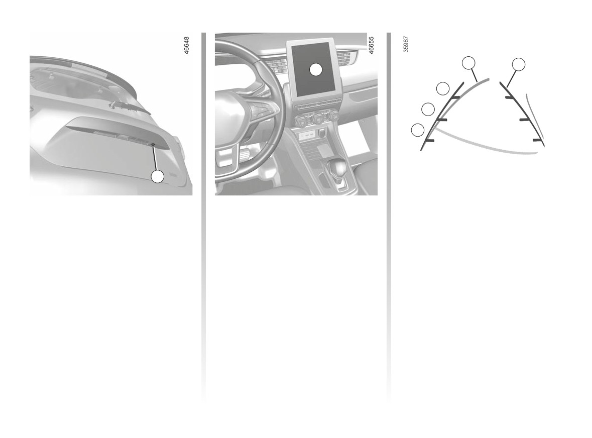
REVERSING CAMERA (1/3)
3
4
2
C
B
A
1
Operation
Fixed clearance gauge 3
4 moving guide line:
When the vehicle is reversing, the
The fixed clearance gauge comprises
This is shown in blue on the multime-
camera 1 on the luggage compart-
coloured markers A, B and C indicating
dia screen 2. It indicates the vehicle tra-
ment lid transmits a view of the area
the distance behind the vehicle:
jectory according to the position of the
surrounding the rear of the vehicle to
steering wheel.
- A (red) approximately 30 centimetres
the multimedia display 2 accompanied
from the vehicle;
by two guiding lines 3 and 4 (fixed and
- B (yellow) approximately 70 centime-
Special feature
mobile).
tres from the vehicle;
Make sure that the camera is not ob-
This system uses several guidelines for
- C (green) approximately 150 centi-
scured (by dirt, mud, snow, condensa-
its operation (mobile for trajectory and
metres from the vehicle.
tion etc.).
fixed for distance). When the red zone
This gauge remains fixed and indicates
is reached, use the bumper image to
the vehicle trajectory if the wheels are
stop accurately.
in line with the vehicle.
2.70
CarManuals2.co
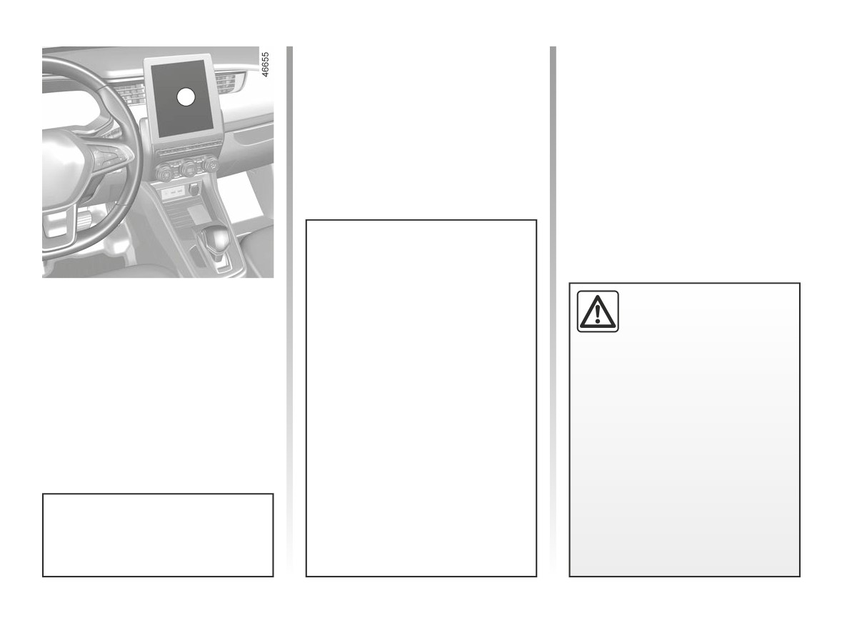
REVERSING CAMERA (2/3)
2
The screen shows a reverse mirror
image.
Activating, deactivating the
This function is an additional
The frames are a representation
reversing camera
aid. It cannot, therefore,
projected on a flat surface. This in-
under any circumstances
With the vehicle stationary and the
formation is to not be taken into ac-
replace the vigilance or the
engine running, from the multimedia
count when superimposed on a
responsibility of the driver.
screen 2 you can add or remove the
vertical object or an object on the
guides and adjust the camera image
ground.
The driver should always be ready
settings
(brightness, contrast etc.).
for sudden incidents while driv-
Objects which appear on the edge
Please refer to the multimedia instruc-
ing: always ensure that there are
of the screen may be deformed.
tions for further information.
no small, narrow moving obstacles
In very bright light (snow, vehicle in
(such as a child, animal, pushchair,
sunshine, etc.), the camera vision
bicycle, stone, post, etc.) in the blind
may be adversely affected.
spot when manoeuvring.
If the boot is open or poorly closed,
the message “Tailgate open” ap-
Each time the vehicle is started,
pears and the camera display dis-
the function continues the mode
appears.
saved the last time the engine was
stopped.
2.71
CarManuals2.co
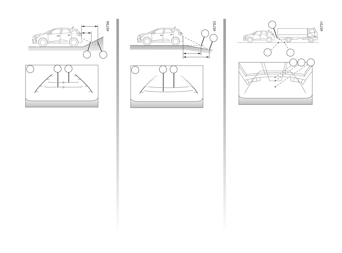
REVERSING CAMERA (3/3)
H
F
G
K
J
D E
H J K
3
D
E
G
F
3
Difference between the
Reversing towards a steep downhill
Reversing towards a protruding
slope
object
estimated distance and
actual distance
The fixed guidelines 3 show the dis-
Position H seems further than posi-
tances as further than they actually are.
tion J on the screen. However, posi-
Reversing towards a steep uphill
tion H is at the same distance as posi-
Therefore, the objects shown on the
slope
tion K.
screen are actually closer on the slope.
The fixed guidelines 3 show the dis-
The trajectory indicated by the fixed
For example, if the screen displays an
tances as closer than they actually are.
and mobile guidelines do not take into
object at G, the actual distance of the
account the height of the object. So
The objects shown on the screen are
object is at F.
there is a risk that the vehicle may col-
actually further away on the slope.
lide with the object when reversing to-
For example, if the screen displays an
wards position K.
object at D, the actual distance of the
object is at E.
2.72
CarManuals2.co
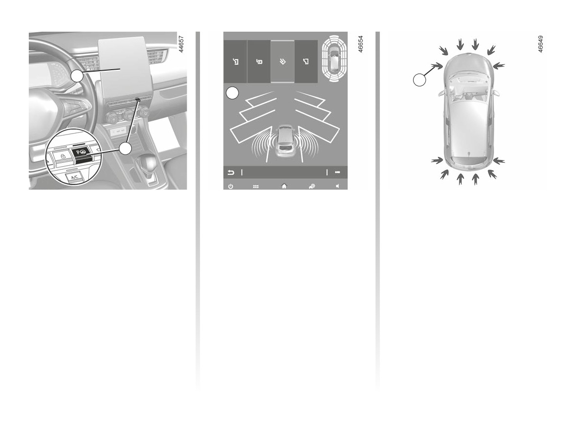
ASSISTED PARKING (1/5)
1
3
A
2
Using ultrasonic detectors as indicated
Switching on
Special features
by the 3 arrows installed in the vehicle
While the engine is running, vehicle
Ensure that the ultrasonic sensors indi-
bumpers, this function helps to find ac-
stationary or driving at less than ap-
cated by arrows 3 are not obscured (by
cessible parking spaces and assists in
proximately 19 mph (30 km/h):
dirt, mud, snow, etc.).
the parking manoeuvre.
- press switch 2. The indicator light in
Remove your hands from the steering
switch 2 lights up and display A ap-
wheel, you only control:
pears on the multimedia screen 1.
- the accelerator pedal;
- set the direction indicator to the side
- the brake pedal;
of the vehicle where you want to
park.
- the gear lever.
You can retake control at any time by
operating the steering wheel.
2.73
CarManuals2.co
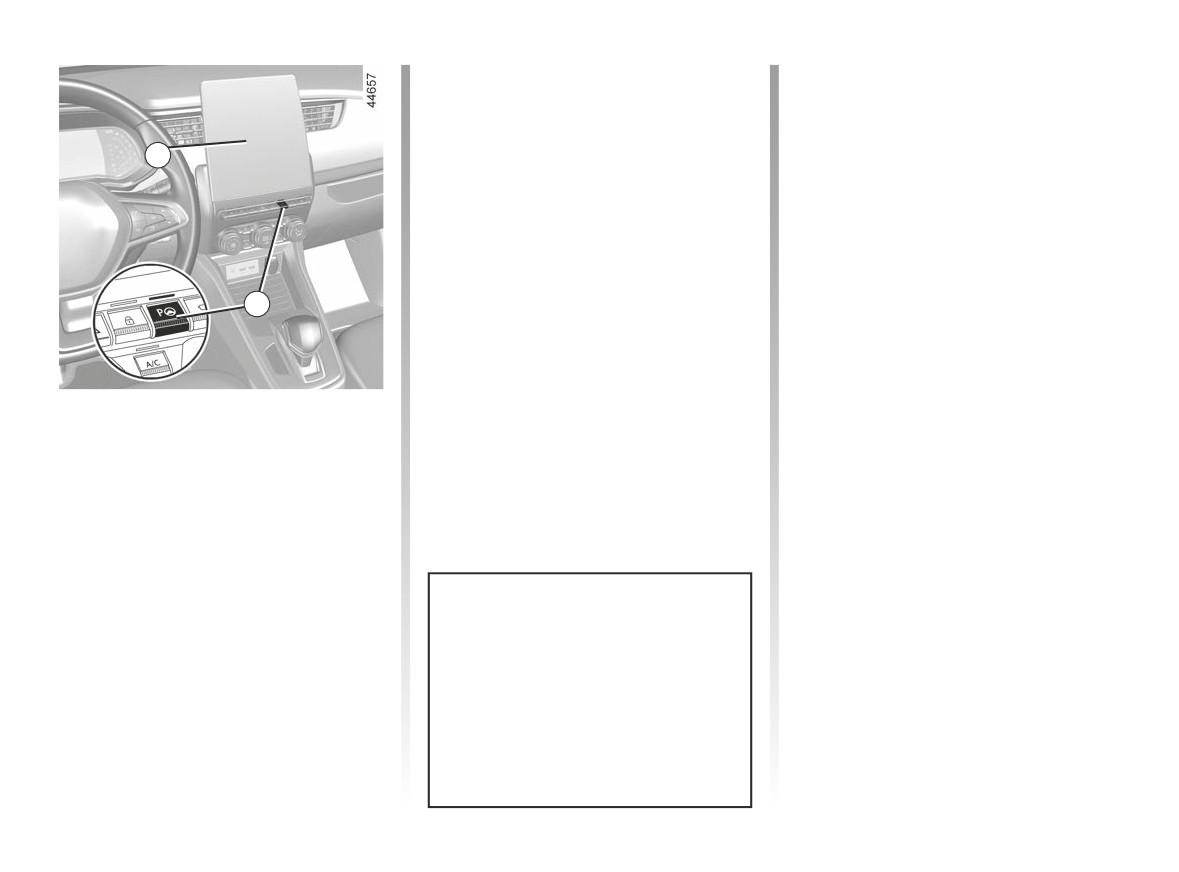
ASSISTED PARKING (2/5)
Note: when starting the vehicle, or after
Operation
having successfully completed parallel
parking using the system, the default
Parking
manoeuvre proposed by the system is
As long as the vehicle speed is less
1
assistance in exiting a parallel parking
than 19 mph (30 km/h), the system
space. In other cases, the default ma-
searches for available parking spaces
noeuvre can be set from the multimedia
on the side of the vehicle chosen by the
screen 1. Please refer to the multime-
driver.
dia instructions for further information.
Note: if parking spaces are available
on the other side of the vehicle, set the
direction indicator to the other direc-
2
tion to enable the system to search for
spaces.
Once a space has been found, it is dis-
played on the multimedia screen, indi-
Choice of manoeuvre
cated by a small letter “P”. Drive slowly,
with the direction indicators activated
The system can perform four types of
on the side where the space is avail-
manoeuvres:
able, until the “Stop” message is dis-
- parallel parking;
played and a beep sounds.
- perpendicular parking;
- angle parking;
- moving out of a parallel parking
space.
From the 1 multimedia screen, select
the manoeuvre to carry out.
The system start up is accompa-
nied by activation of the parking dis-
tance control and, on those vehicles
equipped, the reversing camera to
help the driver visualise the ma-
noeuvre. ➥ 2.63, ➥ 2.70.
2.74
CarManuals2.co
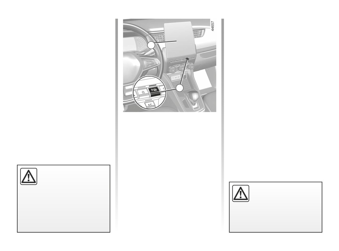
ASSISTED PARKING (3/5)
The space is then indicated on the mul-
- Release the steering wheel;
timedia screen by a capital letter “P”.
- carry out manoeuvres at the front
- Stop the vehicle;
and rear by following the instructions
shown on the multimedia screen 1
– select reverse gear.
1
and using the parking distance con-
trol system alerts.
The indicator light
lights up
on the instrument panel and a beep
Your speed should not exceed around 4
sounds.
mph (7 km/h).
- Release the steering wheel;
Once the vehicle is in a position to exit
- follow the instructions shown on the
the parking space, the
warning
2
multifunction screen 1.
light disappears from the instrument
Your speed should not exceed around 4
panel and a sound signal and message
mph (7 km/h).
appear on the multimedia screen 1 to
confirm that the manoeuvre is com-
Exiting a parallel parking space
plete.
Once the warning light
on the
instrument panel goes off and a beep
- Briefly press the 2 switch;
sounds, the manoeuvre has been com-
- select “Exit parallel parking space”
pleted.
mode;
- activate the direction indicator on the
side you wish to go out of;
- press and hold switch 2 (approx. two
seconds).
This function is an addi-
tional driving aid.
The indicator light
lights up
Therefore, it can under no
on the instrument panel and a beep
When manoeuvring, the
circumstances replace the
sounds.
steering wheel may turn
driver’s vigilance and responsibility
quickly: do not put your
during manoeuvres (the driver must
hands inside, and make
always be ready to brake).
sure that nothing is caught inside.
2.75
CarManuals2.co
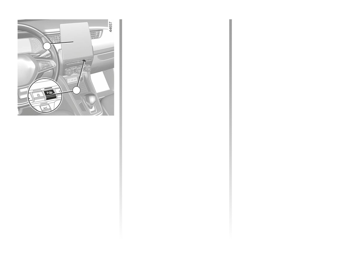
ASSISTED PARKING (4/5)
The warning light on the 2 switch turns
Cancelling the manoeuvre
off and the
warning light disap-
The manoeuvre is cancelled in the fol-
pears from the instrument panel and a
lowing cases:
1
sound signal confirms that the manoeu-
- the vehicle speed has exceeded 4
vre has been suspended. The reason
mph (7 km/h);
for suspending the manoeuvre will be
- by pressing switch 2;
displayed on the multimedia screen 1.
- you have performed more than ten
Make sure:
forwards/backwards movements in
- you have released the steering
one manoeuvre;
wheel;
2
- the parking distance control sensors
and
are dirty or blocked;
- that all doors and the boot are closed;
- the vehicle wheels have skidded;
and
- the manoeuvre has been suspended
- that no obstacles are in the way of
Suspending/Resuming the
for too long.
the direction of movement;
manoeuvre
The warning light on the 2 switch turns
and
The manoeuvre is suspended in the fol-
- that the engine is started.
off and the
warning light disap-
lowing circumstances:
If the warning light on the 2 switch
pears from the instrument panel and a
- you take control of the wheel;
flashes, this indicates that the system
sound signal confirms that the manoeu-
is once again available to resume the
vre has been cancelled. The reason for
- the vehicle is stationary for too long;
manoeuvre.
cancelling the manoeuvre will be dis-
- an obstacle in the direction of move-
played on the multimedia screen 1.
To resume the manoeuvre, press and
ment prevents the manoeuvre from
hold the 2 switch. The warning light on
being completed;
- the engine stops;
the 2 switch comes on and
is
displayed on the instrument panel.
- a door or the luggage compartment
is opened.
Follow the instructions shown on the
multimedia screen 1.
2.76
CarManuals2.co

ASSISTED PARKING (5/5)
This function is an additional driving aid. This function is not under any circumstances intended to replace the due care
and attention of the driver, who should at all times be in control of the vehicle. Make sure that the manoeuvre complies
with the applicable traffic regulations in your location.
The driver should always be ready for sudden incidents while driving: always ensure that there are no small, narrow
moving obstacles (such as a child, animal, pushchair, bicycle, stone, post, etc.) in the blind spot when manoeuvring.
System servicing/repairs
- In the event of an impact, the alignment of the sensors may be changed and their operation may consequently be affected.
Deactivate the function and consult an authorised dealer.
- Any work in the area where the sensors are located (repairs, replacements, exterior trim modifications, etc.) must be carried
out by a qualified professional.
Only an authorised dealer is qualified to service the system.
In the event of system disturbance
Certain conditions may disrupt or impair operation of the system, such as poor weather conditions (snow, hail, ice etc.).
In the event of the system behaving abnormally, deactivate it and consult an authorised dealer.
Risk of erroneous false alarms.
Limitations of the system operation
- The system cannot detect objects located in the sensor blind spots.
- Always visually check that the parking space proposed by the system is still available and contains no obstacles.
2.77
CarManuals2.co

2.78
CarManuals2.co

Section 3: your comfort
Air vents
3.2
Manual air conditioning
3.4
Automatic climate control
3.7
Air conditioning: programming
3.11
Air conditioning: information and advice on use
3.13
Multimedia equipment
3.15
Electric windows
3.16
Interior lighting
3.18
Sun visor
3.18
Passenger compartment storage, fittings
3.19
Ashtray
3.22
Accessories socket
3.22
Rear bench seat: functions
3.24
Rear parcel shelf
3.25
Luggage cover
3.26
Luggage compartment
3.27
Spoiler
3.27
Transporting objects in the luggage compartment
3.28
3.1
CarManuals2.co
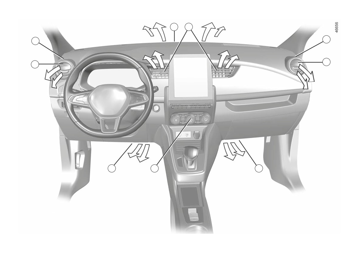
AIR VENTS: air outlets (1/2)
3
4
2
2
1
1
5
6
5
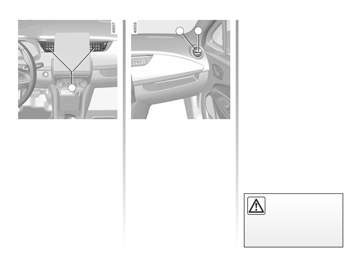
1 side air vent.
4 centre air vents.
2 side demister outlet.
5 passenger footwell heater outlets.
3 windscreen demisting vents.
6 control panel.
3.2
CarManuals2.co
AIR VENTS: air outlets (2/2)
To remove bad odours from your ve-
hicles, only use the systems designed
1
7
for this purpose. Consult an approved
Dealer.
4
Centre air vents.
Side air vents
Direction
Air flow
Move cursors 4 to the required position.
To open air vent 1, press on the air vent
(point 7) until it is open as far as re-
quired.
Direction
To direct the air flow, swivel side air
vent 1.
Do not add anything to the
vehicle’s ventilation circuit
(for example, to remove
bad odours).
There is a risk of damage or of
fire.
3.3
CarManuals2.co
MANUAL AIR CONDITIONING (1/3)
The air conditioning system is used
1
2
3
4
5
for:
- lowering the temperature inside the
passenger compartment;
- eliminating condensation more
quickly.
Advice: to optimize vehicle range, de-
activate the air conditioning when the
outside temperature is comfortable.
Adjusting the ventilation
speed
7
6
Turn the control 3 to one of the eight
positions to start the ventilation system
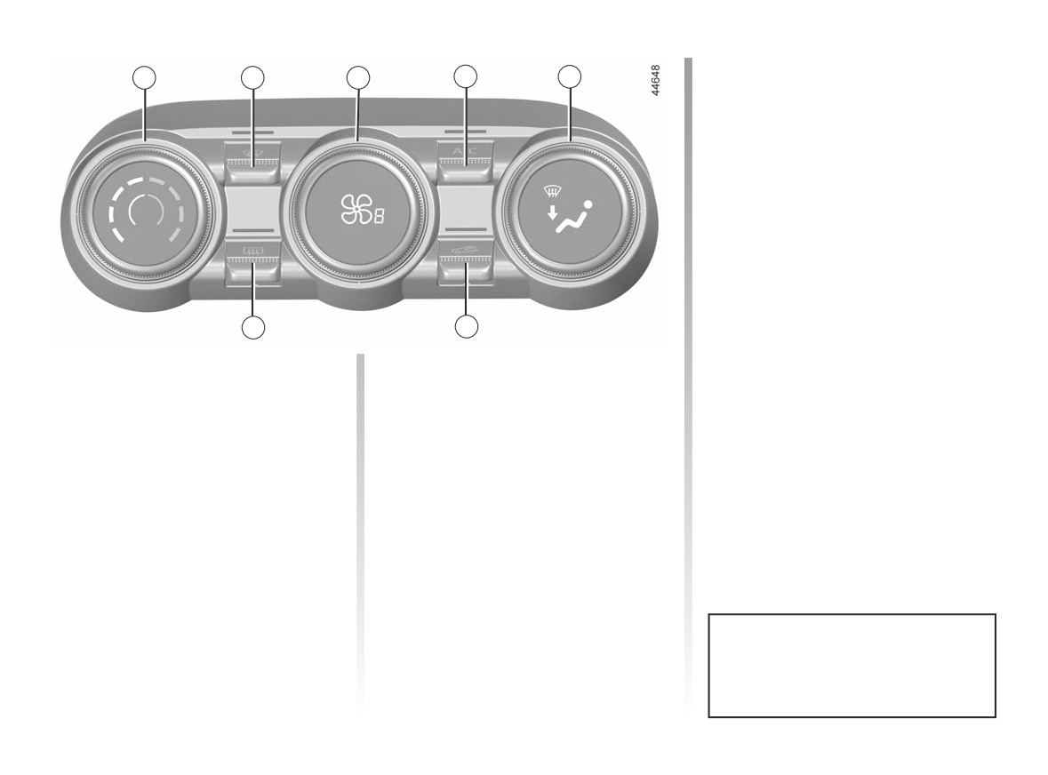
The controls
Switching air conditioning on
and adjust the power.
or off
1 Adjusting the air temperature.
Position OFF
(depending on vehicle)
2 “Clear View” function.
In this position:
3 Push button to adjust fan speed and
The air conditioning is switched on (in-
- the air conditioning switches off au-
stop the system.
dicator light on) or off (indicator light off)
tomatically;
4 Air-conditioning activation control.
using button 4.
- the ventilation speed of air in the
5 Passenger compartment air distribu-
passenger compartment is zero;
The system cannot be switched on if
tion adjustment.
- there is, however, a slight flow of air
the control 3 is set to OFF.
6 Air recirculation.
when the vehicle is moving.
7 De-icing/demisting of the rear screen
This position should not normally be
and, depending on the vehicle, the
used.
door mirrors.
Heating or air-conditioning can only be
used while the engine is running.
Some buttons have an operating
tell-tale which indicates the operat-
ing status.
3.4
CarManuals2.co
MANUAL AIR CONDITIONING (2/3)
The air flow is directed towards
1
3
5
ö
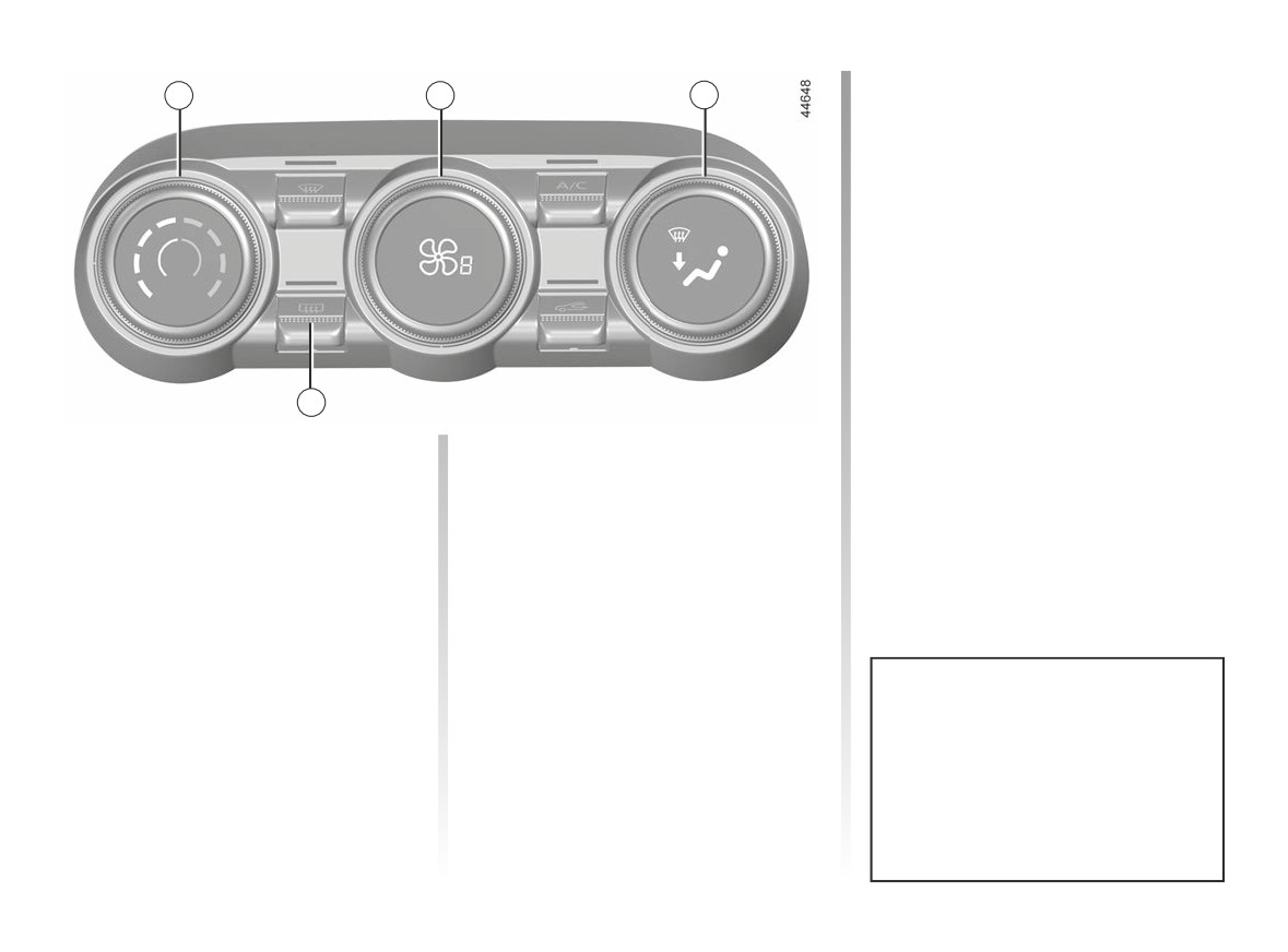
the dashboard vents and to-
wards the footwells.
The air flow is mainly directed
ô
to the dashboard air vents.
ó
owards the footwells.
Rear screen de-icing/
demisting
Press the 7 button: the integrated indi-
cator light comes on. This function ena-
7
bles rapid demisting/de-icing of the rear
screen and the rear view mirrors (on
Adjusting the air temperature
Adjusting the distribution
equipped vehicles).
Turn the control 1 to one of the eight
of air in the passenger
To exit this function, press button 7
positions to set the temperature. The
compartment
again. Demisting automatically stops.
further towards the red the slide is, the
Turn control 5 to choose the distribution
higher the temperature will be.
option.
When the air conditioning system is
All the air is then directed to
used for long periods, it may begin to
W
the windscreen and front side
feel cold. To increase the temperature,
window demisting vents.
turn control 1 to the right.
The air flow is distributed be-
tween front side window de-
misting vents, the windscreen demist-
Recommendations
ing vents and the footwells.
In the event of freezing, manu-
ally de-ice the windscreen using a
scraper rather than the de-icing/de-
misting function in order to reduce
your energy consumption.
3.5
CarManuals2.co
MANUAL AIR CONDITIONING (3/3)
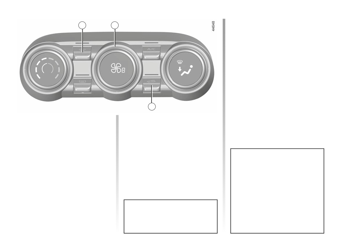
Air recirculation is for:
2
3
- isolating the vehicle from the exter-
nal atmosphere (driving in polluted
areas, etc.);
- lowering the passenger compart-
ment temperature as quickly as pos-
sible.
Stopping the system
Press button 3.
6
Clear View function
Switching the air
recirculation on
Press the 2 button: the integrated indi-
cator light comes on.
Press button 6: the integrated indicator
This system quickly demists and de-
light comes on. In these conditions, air
ices the windscreen and the front side
is taken from the passenger compart-
windows. It requires the automatic
ment and is recycled, with no air being
usage of the air-conditioning or the
taken from outside the vehicle.
heating.
Prolonged use of air recirculation
can lead to condensation forming on
To exit this function, select the adjust-
the side windows and windscreen,
ment required (distribution, ventilation
and discomfort due to the use of
speed, temperature, air recirculation).
non-renewed air in the passenger
compartment. We therefore advise
you to return to normal mode (exter-
nal air) as soon as the air recircula-
The demisting/de-icing will still take
tion function is no longer required,
priority over the air recirculation.
by pressing the button 6 again.
3.6
CarManuals2.co
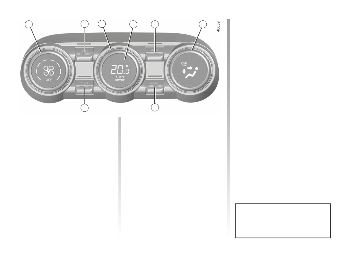
AUTOMATIC CLIMATE CONTROL (1/4)
Adjusting the ventilation
1
2
3
4
5
6
speed.
In automatic mode, the system uses
the most suitable amount of air to reach
and maintain the desired comfort level.
You can still adjust the ventilation
speed by turning control 1 to increase
or reduce the ventilation speed.
Adjusting the air temperature
Turn control 3 to obtain the desired
temperature.
8
7
Turning the control to the right in-
creases the temperature.
The controls
Automatic mode
Note: to increase the vehicle range,
(depending on the vehicle)
The automatic climate control system
reduce the comfort level by turning
guarantees comfort in the passen-
1
Adjusting the ventilation speed and
the 3 control
ger compartment and good visibility
OFF position.
(except in the event of extreme condi-
2
“Clear View” function.
tions), while optimising fuel consump-
3
Adjusting the air temperature.
tion. The system controls the ventilation
speed, air distribution, air recirculation,
4
Automatic mode.
and starting and stopping the air condi-
5
Air conditioning control.
tioning and air temperature.
6
Distribution of air in the passenger
AUTO: allows the selected comfort
compartment.
level to be best attained, depending on
the exterior conditions. Press button 4.
7
Air recirculation.
8
De-icing/demisting of the rear screen
Any action on a button other than
and, depending on the vehicle, the
the AUTO button triggers deactiva-
rear view mirrors.
tion of automatic mode.
3.7
CarManuals2.co
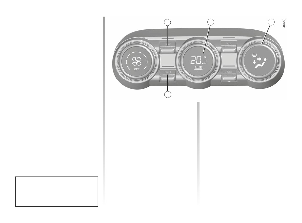
AUTOMATIC CLIMATE CONTROL (2/4)
Clear View function
2
4
6
Press the 2 button: the integrated indi-
cator light comes on.
This function quickly de-mists the wind-
screen, rear screen, front side windows
and door mirrors (depending on the
vehicle). The air conditioning and rear
screen de-icing functions must be ac-
tivated.
Press button 8 to stop the heated rear
screen operating, and the integrated in-
dicator goes out.
To exit this function, press button 2
8
or 4.
Adjusting the distribution
The air flow is directed towards
ö
the dashboard vents and to-
of air in the passenger
wards the footwells.
compartment
The air flow is mainly directed
Turn control 6. The integrated warning
ô
to the dashboard air vents.
light in the button comes on.
All the air is then directed to
ó
owards the footwells.
W
the windscreen and front side
window demisting vents.
The air flow is distributed be-
tween front side window de-
misting vents, the windscreen demist-
ing vents and the footwells.
Some buttons have an operating
tell-tale which indicates the operat-
ing status.
3.8
CarManuals2.co
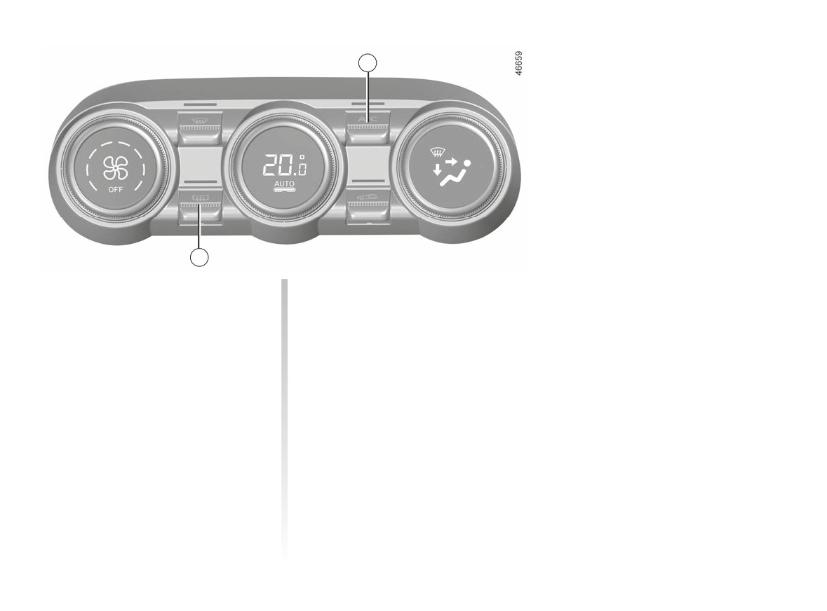
AUTOMATIC CLIMATE CONTROL (3/4)
5
8
Rear screen de-icing/
Switching air conditioning on
demisting
or off
Press the 8 button: the integrated in-
In automatic mode, the system switches
dicator light comes on. This function
the air conditioning system on or off,
enables rapid demisting or de-icing of
depending on the climate conditions.
the rear screen and de-icing of the rear
Press the button 5 to force the air con-
view mirrors (on equipped vehicles).
ditioning to stop. The integrated warn-
To exit this function, press button 8
ing light will go out.
again. Demisting automatically stops.
3.9
CarManuals2.co