Renault Zoe (2023 year). Manual in english - page 3
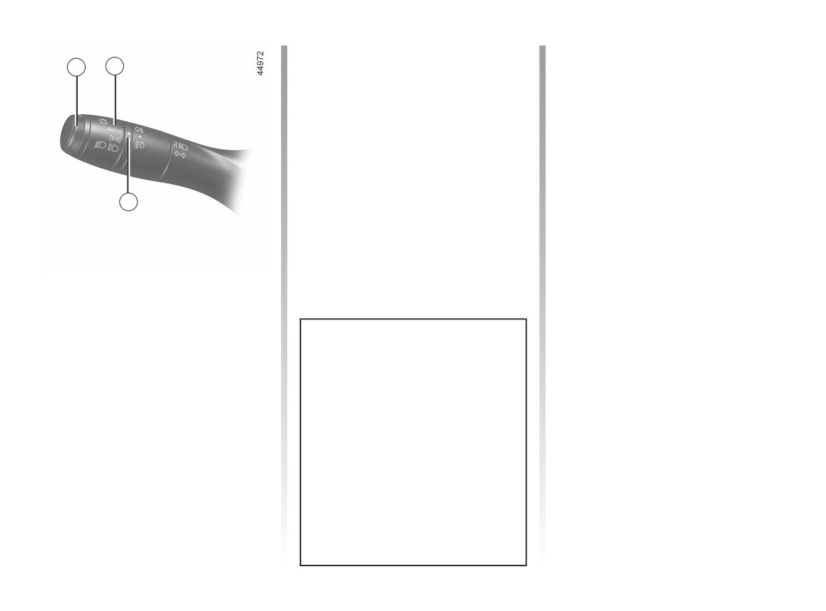
EXTERIOR LIGHTING AND SIGNALS (2/6)
Automatic main beam
The main beam headlights come on au-
2
tomatically if:
1
headlights
- exterior light is weak;
Depending on the vehicle, this system
- no other vehicles or lighting are de-
switches the main beam headlights on
tected;
and off automatically. It uses a camera
- the vehicle speed is above approxi-
located behind the interior rear-view
mately 25 mph (40 km/h).
mirror to detect vehicles that are being
If any of the above conditions are not
followed and those coming in the oppo-
fulfilled, the system switches to dipped
site direction.
beam headlights.
3
Note: make sure the windscreen is not
obscured (dirt, mud, snow, condensa-
tion etc.).
To activate automatic main beam
headlights:
Main beam headlights
á
Turn ring 2 until the AUTO symbol is op-
With the engine running and
posite mark 3 and push the stalk 1.
the dipped beam headlights lit, push
stalk 1. This indicator light on the instru-
Warning light
comes on the in-
ment panel comes on.
The system may encounter difficul-
strument panel.
To return to the dipped headlight posi-
ties under certain conditions, inclu-
tion, pull the stalk 1 towards you again.
ding:
- extreme weather conditions (rain,
snow, fog, etc.);
- obstruction in front of the wind-
screen or camera;
- when a following or oncoming ve-
hicle has weak or hidden lighting;
- incorrect settings for the front
headlights;
- reflective systems;
– ...
1.100
CarManuals2.co
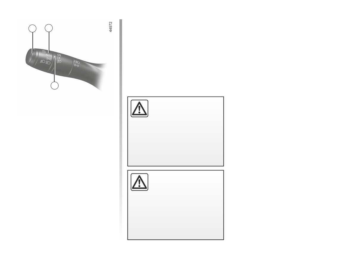
EXTERIOR LIGHTING AND SIGNALS (3/6)
Operating faults
1
2
When the message “Check Automatic
Lighting” appears on the instrument
panel, the system is deactivated.
Consult an approved dealer.
3
Using the portable naviga-
tion system at night in the
windscreen area below the
Automatic main beam
camera may disturb the op-
headlights (continued)
eration of the “automatic main beam
headlights” system (risk of reflection
To deactivate automatic main beam
on the windscreen).
headlights:
- turn ring 2 to a position other than
AUTO;
or
The “automatic main beam
- pull the stalk 1.
headlights” system should
under no circumstances be
Warning light
goes out on the in-
used to replace driver atten-
strument panel.
tion and responsibility with regard
to vehicle lighting and adapting to
light, visibility and traffic conditions.
1.101
CarManuals2.co
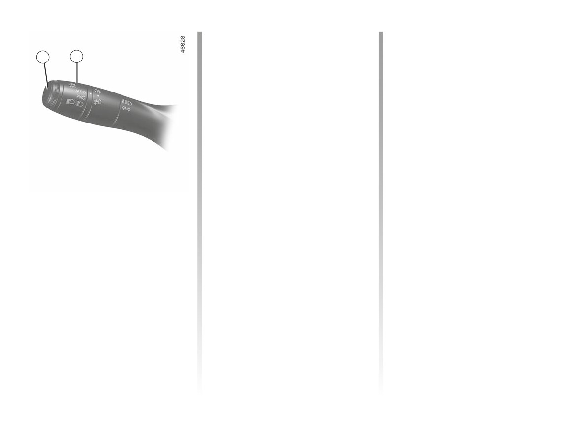
EXTERIOR LIGHTING AND SIGNALS (4/6)
Lights-on reminder buzzer
Welcome and goodbye
If the lights are on after the engine is
function
1
2
(depending on the vehicle)
switched off, a warning beep sounds
when the driver’s door is opened to
Once the function is activated, the day-
warn you that the lights are still on.
time running lights and the rear side
lights will light up automatically upon
detection of the card or when the vehi-
Operating faults
cle is unlocked.
If the
“Check lighting” message ap-
They switch off automatically:
- approximately one minute after light-
the k
warning light flashes on the
ing up;
instrument panel, this indicates a light-
- when starting the engine based on
ing fault.
the position of the lighting stalk;
Consult an authorised dealer.
or
Switching off the lights
- upon locking the vehicle.
The lights will go out automatically
when the engine is switched off, the
driver's door is opened or the vehicle
Activating/deactivating the
is locked. In this case, the next time
function
the engine is started the lights will be
With the vehicle stationary, engine run-
switched back on according to the posi-
ning, from the multimedia screen select
tion of the ring 2.
the “Settings” menu, “Vehicle” tab, the
Note: if the fog lights are lit, the lights
“Car configuration” menu, “Welcome”
are not switched off automatically.
then “External welcome”. Choose “ON”
or “OFF” to activate or deactivate the
function.
1.102
CarManuals2.co
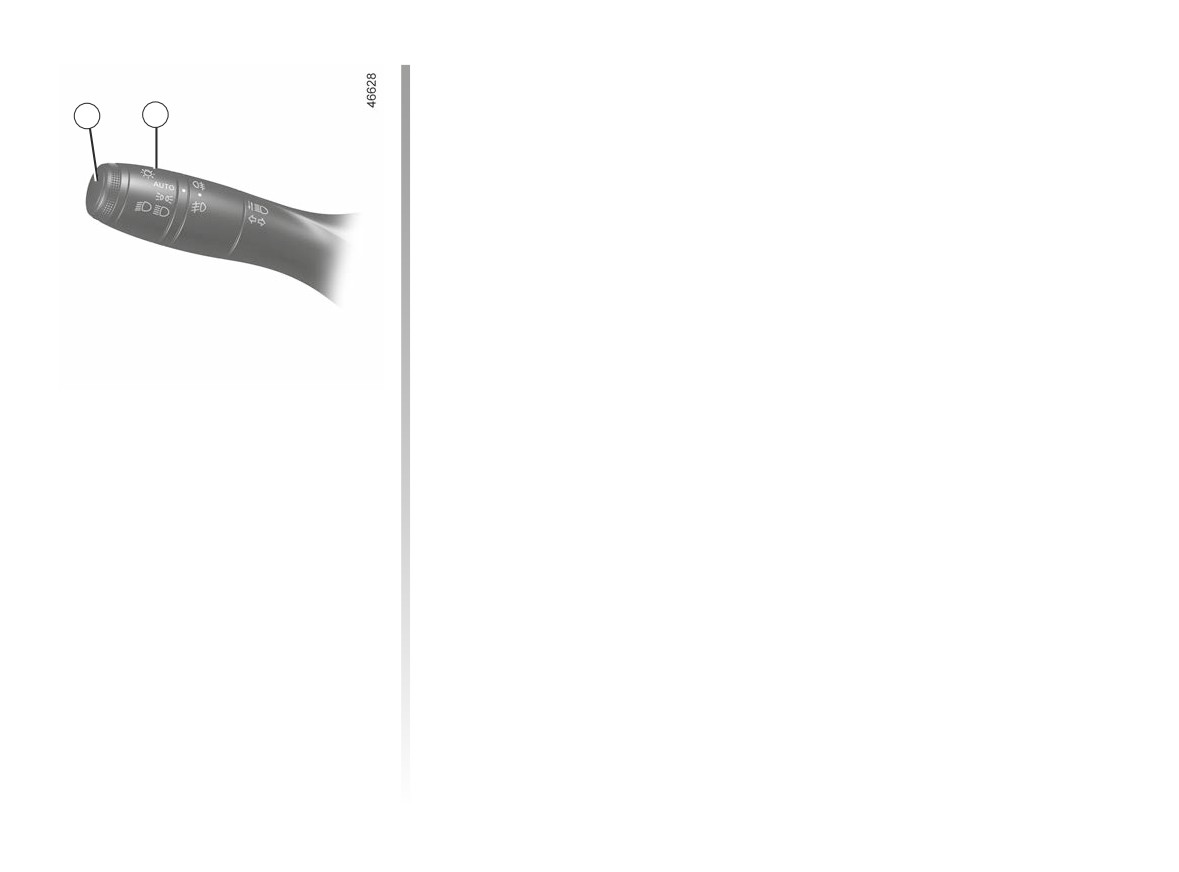
EXTERIOR LIGHTING AND SIGNALS (5/6)
With the engine lights switched off,
the 2 ring in AUTO, pull the lever 1 to-
1
2
wards you: the side lights and dipped
beam headlights will switch on for ap-
proximately 30 seconds along with the
š
and k
on the instrument
panel.
To increase this duration, you may pull
the stalk up to four times (total time re-
stricted to approximately two minutes).
On the instrument panel, the message
“lighting on _ _ _” followed by the re-
maining time will appear as confirma-
tion. You can then lock your vehicle.
“See-me-home lighting”
To switch off the lights before they go
out automatically, turn ring 2 to any po-
function
sition, then return it to position AUTO.
This function enables you to briefly
switch on the side lights and dipped
beam headlights (e.g. to provide light
when opening a gate).
1.103
CarManuals2.co
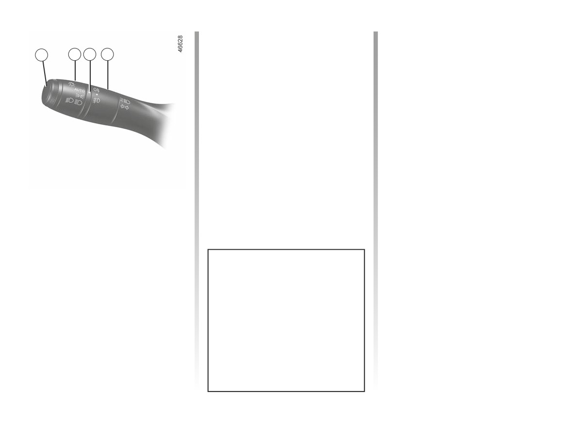
EXTERIOR LIGHTING AND SIGNALS (6/6)
Rear fog light
Switching off the lights
Turn centre ring 4 on the stalk
Turn the centre ring 4 again until mark 3
1
2
3
4
until the symbol faces mark 3, then re-
is opposite the symbol for the fog lights
lease it.
that you wish to switch off. The corre-
sponding indicator light on the instru-
Operation of the fog lights depends on
ment panel goes out.
the exterior lighting selected, and an in-
dicator light will light up on the instru-
The front and rear fog lights switch off
ment panel.
when the exterior lights are switched
off.
To avoid inconveniencing other road
users, remember to switch off the rear
fog light when it is no longer needed.
Cornering lights
(depending on vehicle)
Driving in forward gear, whenever the
dipped beam headlights are on and
Front fog lights
under certain conditions (at speed, the
g
steering wheel at an angle, the indica-
Turn centre ring
4
on
the
tor lights on, etc.), when taking a corner
stalk 1 until the symbol faces mark 3,
one of the front fog lights will switch on
then release it.
to light the inside of the bend.
Operation of the fog lights depends on
In reverse, the two front fog lights
the exterior lighting position selected,
switch on automatically.
and an indicator light will light up on the
When driving in fog or snow, or
instrument panel.
when transporting objects which are
higher than the roof, the headlights
do not come on automatically.
The driver remains in full control of
switching on the fog lights: the indi-
cator lights on the instrument panel
inform you whether the fog lights
are lit (indicator light on) or not (indi-
cator light off).
1.104
CarManuals2.co
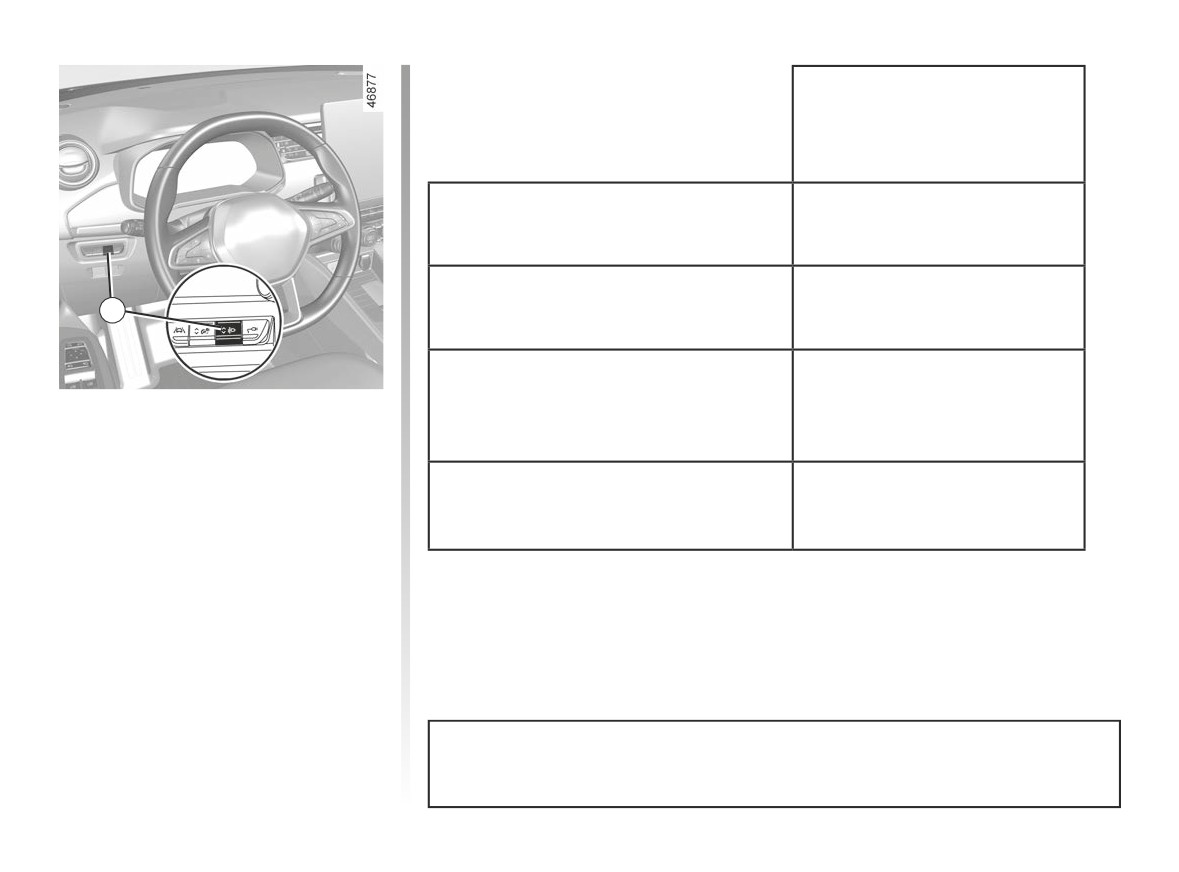
HEADLIGHT BEAM ADJUSTMENT
Examples of positions for
adjusting
control A according to the load
Driver alone or with front passenger
0
A
All seats occupied
1
Driver with passengers and luggage
Switch A is used to adjust the height of
(or load) reaching the maximum
2
the headlight beams according to the
permissible all-up weight
load.
With the dipped beam headlights lit,
Driver without passengers and luggage
press or lift switch A as many times
(or load) reaching the maximum
3
as is necessary to select the required
permissible all-up weight
position on the instrument panel. The
position selected is displayed on the
* depending on the vehicle
instrument panel for approximately
30 seconds.
The table below gives some examples. In all cases, adjust control A accord-
Note: lights on, at each engine start-
ing to the vehicle load so that the road can be seen and other drivers are not
up the selected position is displayed on
dazzled.
the instrument panel for approximately
30 seconds.
If driving on the left in a left-hand drive vehicle (or vice versa), drivers must have
the lights adjusted by an authorised dealer for the duration of the trip.
1.105
CarManuals2.co
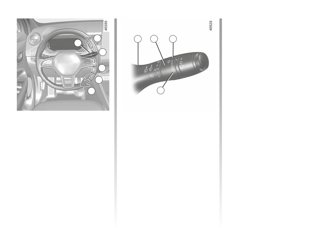
WINDSCREEN WASH, WIPE (1/4)
When activating automatic wiping or
when increasing sensitivity, one sweep
of the blades is performed.
A
1
2
F
1
Note:
B
-
the rain sensor is only intended as a
driving aid. In the event of reduced
visibility, the driver should manually
C
activate the wipers. In foggy weather
or during snowfalls, wiping is not au-
D
tomatically triggered and remains
under the driver’s control;
E
G
-
in the event of temperatures below
zero, automatic wiping is not acti-
vated when the vehicle is started. It
is automatically activated as soon as
Vehicle fitted with front
C
automatic wiper function
the vehicle exceeds a certain speed
windscreen wiper rain sensor
When this position is selected, the
(approximately 5 mph (8 km/h));
system detects water on the wind-
The rain sensor is located on the winds-
-
do not activate automatic wiping in
screen and triggers the wipers at a
creen, in front of the interior rear-view
dry weather;
suitable wiping speed. It is possible to
mirror.
change the triggering threshold and the
-
fully de-ice the windscreen before
time sweeps by turning ring 2:
activating automatic wiping;
A single sweep
- F: minimum sensitivity
-
when washing the vehicle under a
A short push will trigger one sweep of
roller type car wash, return the ring 1
the wipers.
- G: maximum sensitivity
to the B position to deactivate auto-
The higher the sensitivity, the quicker
matic wiping.
B stop
the wipers will react and the faster the
wipe.
1.106
CarManuals2.co
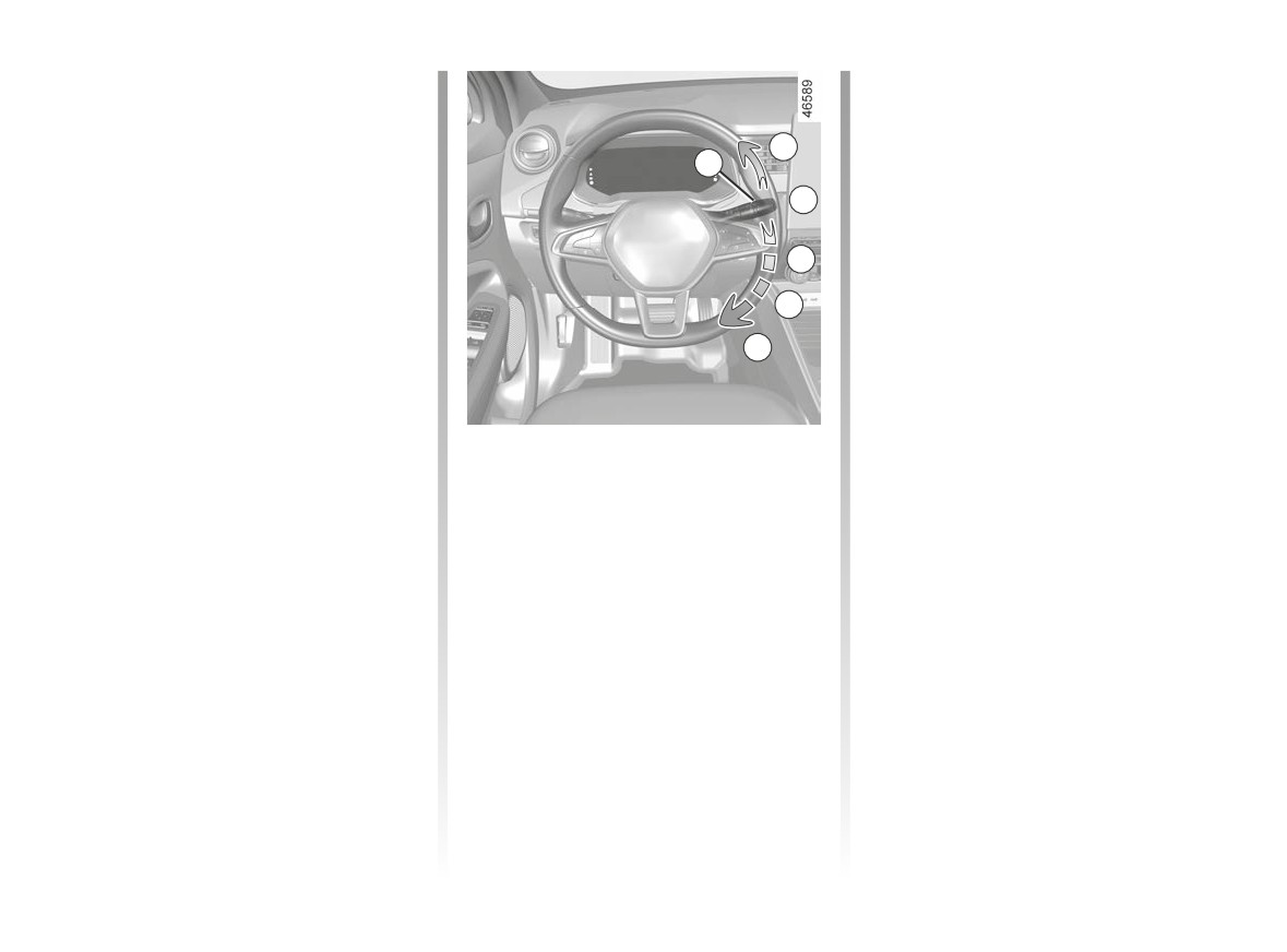
WINDSCREEN WASH, WIPE (2/4)
Operating faults
Special note
In the event of a malfunction of the au-
When driving the vehicle, the wiping
tomatic wiping, the wiper is set to inter-
speed slows down whenever the vehi-
A
mittent wiping. Contact an authorised
cle stops. For example, fast wiping
1
dealer.
speed will slow to normal wiping speed.
B
As soon as the vehicle moves off,
The operation of the rain sensor can be
wiping will return to the speed originally
disturbed in the event of:
selected.
-
damaged windscreen wipers; a film
C
If stalk 1 is operated, it overrides and
of water or traces left by a blade in
D
cancels the automatic function.
the sensor’s detection zone may in-
crease the response time of the au-
E
Precautions
tomatic wiper, or increase the wiping
frequency;
- In the event of ice, check whether the
blades are stuck to the windscreen
-
a windscreen with any chip or crack
before operating the wiping mecha-
level with the sensor, or a windscreen
D
slow continuous wiping
nism. If you activate the wipers while
covered in dust, dirt, insects, ice, the
the blades are stuck down with ice,
use of washing wax and water-repel-
E
fast continuous wiping
you may risk damaging both the
lent chemicals; the windscreen wiper
blade and the wiper motor.
will be less sensitive or may even not
react at all.
- Do not activate the wipers on a dry
screen. This will lead to premature
wear or damage to the blades.
1.107
CarManuals2.co
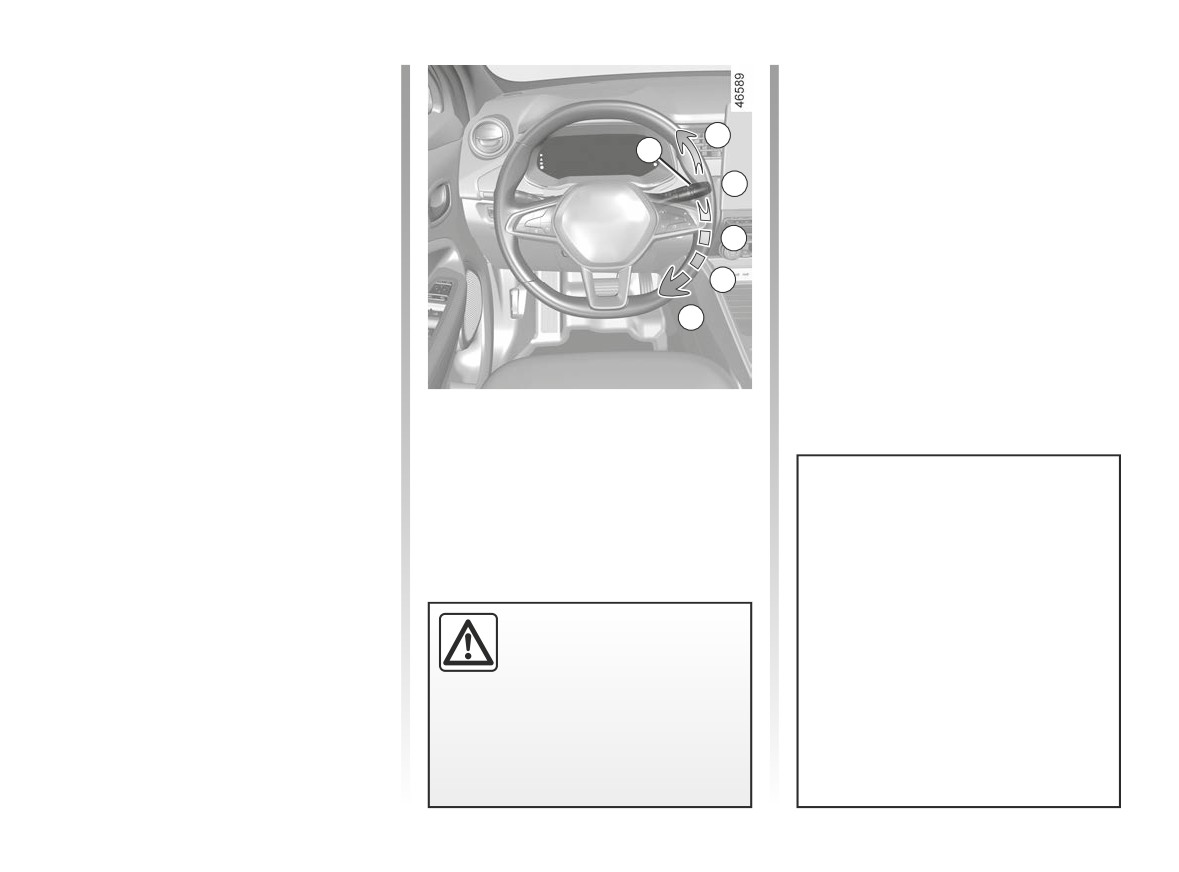
WINDSCREEN WASH, WIPE (3/4)
Specific front wiper position
(service position)
This position enables the blades to be
A
lifted to remove them from the winds-
1
creen.
B
It may be useful to:
- to clean the blades;
C
- to release the blades from the wind-
screen in winter;
D
- replace the blades ➥ 5.21.
E
With the ignition on and the engine off,
lower the windscreen wiper stalk to
position E (fast continuous wipe). The
wiper arms stop in a position away from
the bonnet.
To return the blades into position, make
sure they have been placed on the
windscreen, then move the stalk to po-
sition B (stopped) with the ignition on.
In the event of obstacles on the
windscreen (dirt, snow, ice etc.),
Before switching on the ignition,
clean the windscreen (including the
place the wipers on the windscreen.
central area located behind the inte-
Otherwise, there may a risk of damage
rior rear view mirror) before starting
to the bonnet or the wipers when they
the wipers (risk of motor overheat-
Before any action involving
are switched on.
ing).
the windscreen
(washing
the vehicle,
de-icing,
If an object is preventing a blade
cleaning the windscreen,
from moving, it may stop functio-
etc.) return stalk
1 to position B
ning. Remove the obstacle and
(stop).
reactivate the wiper using the wiper
stalk.
Risk of injury and/or damage.
1.108
CarManuals2.co
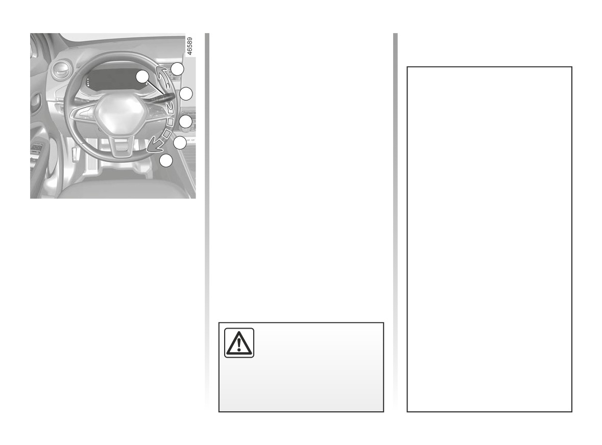
WINDSCREEN WASH, WIPE (4/4)
Note: in temperatures below zero, the
washer liquid may freeze on the wind-
screen, reducing visibility. Heat the
A
windscreen using the demister control
1
before cleaning.
B
Efficiency of a wiper blade
C
Check the condition of the wiper
blades. How long they last depends
D
on you:
E
- it must remain clean: clean the
blade and the screen regularly
with soapy water;
- do not use it when the screen is
dry;
Windscreen washer
- free it from the screen when it has
With the ignition on, pull stalk 1 then
not been used for a long time.
release.
In all cases, replace it as soon as
A longer pull will trigger, in addition to
it begins to lose efficiency: approxi-
the windscreen washer, two sweeps
mately once a year. ➥ 5.21.
of the wipers followed, a few seconds
later, by a third.
Precaution for using the
On vehicles fitted with a multimedia
wipers
screen, you can choose to activate or
disable the third sweep of the blades.
- In freezing or snowy weather
➥ 1.92.
conditions, clear the screen
When working in the engine
before starting the wipers (risk of
compartment, ensure that
motor overheating);
the windscreen wiper stalk
- ensure that no objects are ob-
is in position B (stop).
structing the travel of the blade.
Risk of injury.
1.109
CarManuals2.co
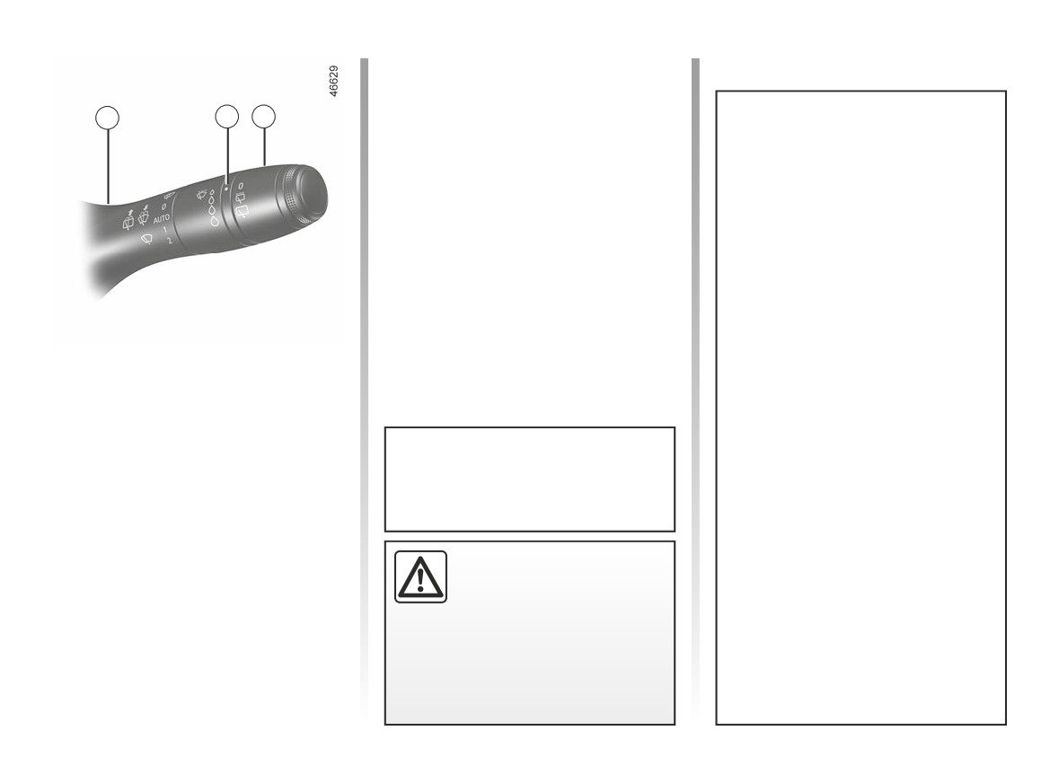
REAR SCREEN WASH, WIPE (1/2)
To stop the operation, pivot ring 3 again.
Note: when washing using a roller
type car wash, return the ring 3 on the
1
2
3
stalk 1 to the stop position to deactivate
automatic wiping.
Follow usage recommendations.
Efficiency of a wiper blade
Check the condition of the wiper
blades. How long they last depends
on you:
- it must remain clean: clean the
blade and the screen regularly
with soapy water;
- do not use it when the screen is
dry;
Rear screen wiper
- free it from the screen when it has
Y
not been used for a long time.
With the ignition on, turn ring 3
on stalk 1 to align the symbol with
In all cases, replace it as soon as
mark 2.
it begins to lose efficiency: approxi-
mately once a year. ➥ 5.21.
- switching off
Do not use the wiper arm to open or
- intermittent wiping
close the tailgate.
Precautions for using the
The wipers will pause for several
seconds between sweeps. Wiping
wipers
frequency varies with vehicle
- In freezing or snowy weather
speed;
Before any action involving
conditions, clear the screen
the rear screen (washing
– slow continuous wiping
before starting the wipers (risk of
the vehicle, de-icing, clean-
motor overheating);
ing, etc.) return stalk 1 to
- ensure that no objects are ob-
the stop position.
structing the travel of the blade.
Risk of injury and/or damage.
1.110
CarManuals2.co
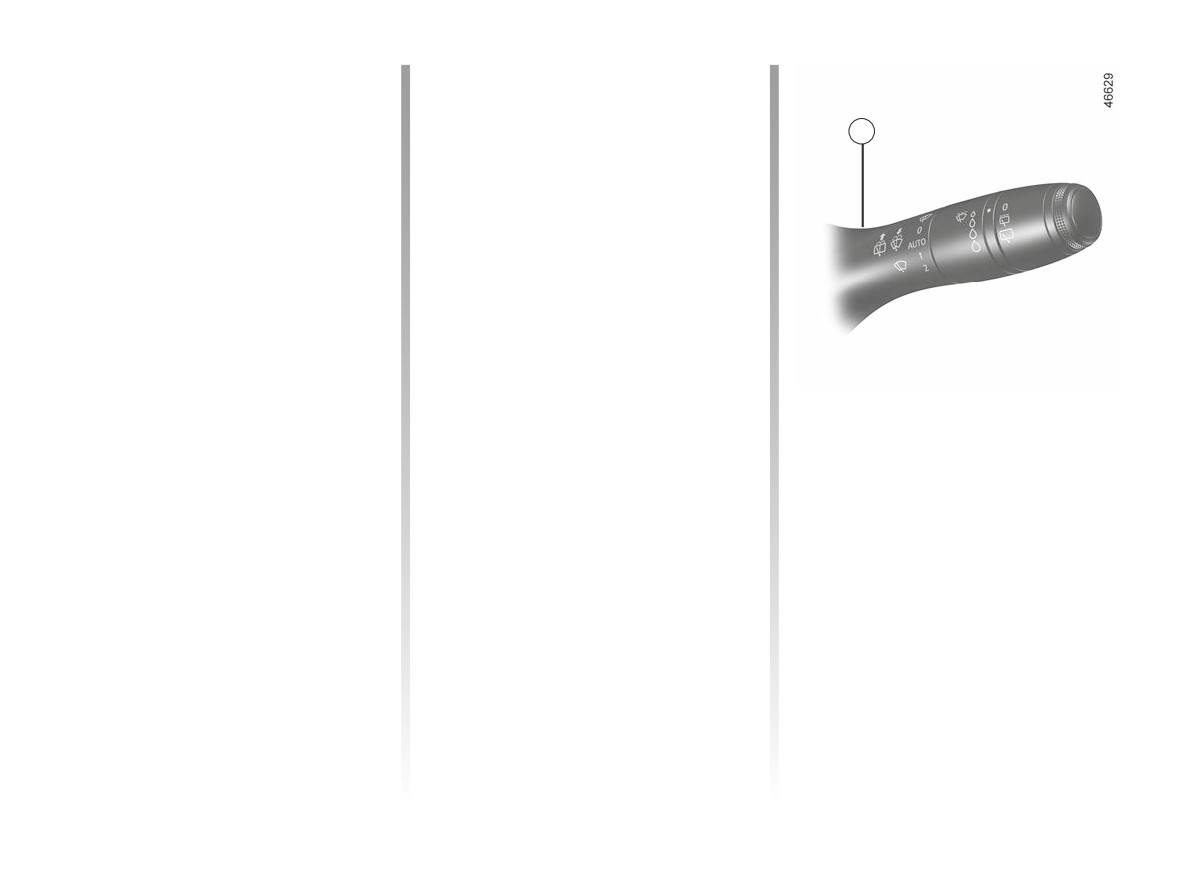
REAR SCREEN WASH, WIPE (2/2)
Activation/deactivation of the rear
In the event of obstacles present on the
screen wiper
rear window (dirt, snow, etc.), the wiper
will try to sweep away all the obstacles.
Engaging reverse gear triggers inter-
If an obstacle prevents the blade from
1
mittent wiping (if the front wipers are in
moving, it can be stopped. Remove the
operation). If your vehicle is equipped
obstacle, wait for around 30 seconds
with a vehicle settings customisation
and reactivate the wiper using the wiper
menu, you can opt to activate or deacti-
stalk.
vate this function. ➥ 1.92.
For vehicles not fitted with a settings
Precautions
customisation menu, you can have this
-
In the event of ice, check that the
function deactivated by an authorised
blades are not stuck to the wind-
dealer.
screen before operating the wipers.
If you activate the wiper while the
blade is blocked by ice, you risk dam-
aging both the blade and the wiping
motor.
Rear screen wash/wipe
p
-
Do not operate the wipers on a dry
With the ignition on, push and
screen. This will lead to the prema-
hold stalk 1, then release.
ture wear or damage to the blades.
Holding the stalk for longer will trigger
(in addition to the windscreen washer)
two sweeps of the wipers followed,
a few seconds later, by a third (drip
wiping function).
When the stalk is released, it returns to
the rear wipe position.
1.111
CarManuals2.co

1.112
CarManuals2.co

Section 2: driving
(Advice on use relating to fuel economy and the environment)
Starting, stopping the engine
2.2
Gear control
2.5
Electronic parking brake
2.8
Environment
2.12
Driving advice, Eco-driving
2.13
Vehicle range: advice
2.16
Tyre pressure monitoring system
2.18
Active emergency braking
2.23
Driver correction devices and aids
2.30
Lane departure warning
2.35
Lane Keeping Assist
2.39
Blind spot warning
2.44
Detection of road signs
2.49
Speed limiter
2.53
Cruise control
2.57
“AUTOHOLD” function
2.62
Parking distance control
2.63
Reversing camera
2.70
Assisted parking
2.72
2.1
CarManuals2.co
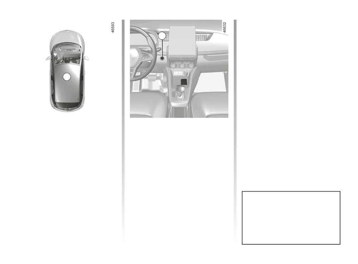
STARTING, STOPPING THE ENGINE (1/3)
2
1
Starting the engine
Special features
The card must be inserted in detection
- If one of the starting conditions is not
zone 1.
applied, the message “Press Brake
+ START” is displayed on the instru-
To start
ment panel;
- depress the brake pedal;
- in some cases, it will be necessary
to move the steering wheel whilst
- press button
2. The message
pressing the start button 2 to help
READY comes on, on the instrument
unlock the steering column; the
panel, along with a beep.
message “Turn Steering Wheel +
The message disappears when the ve-
START” will alert you.
hicle speed is above approximately 3.1
mph (5 km/h).
The vehicle can only be started if
the charging cord is unplugged from
the vehicle.
2.2
CarManuals2.co
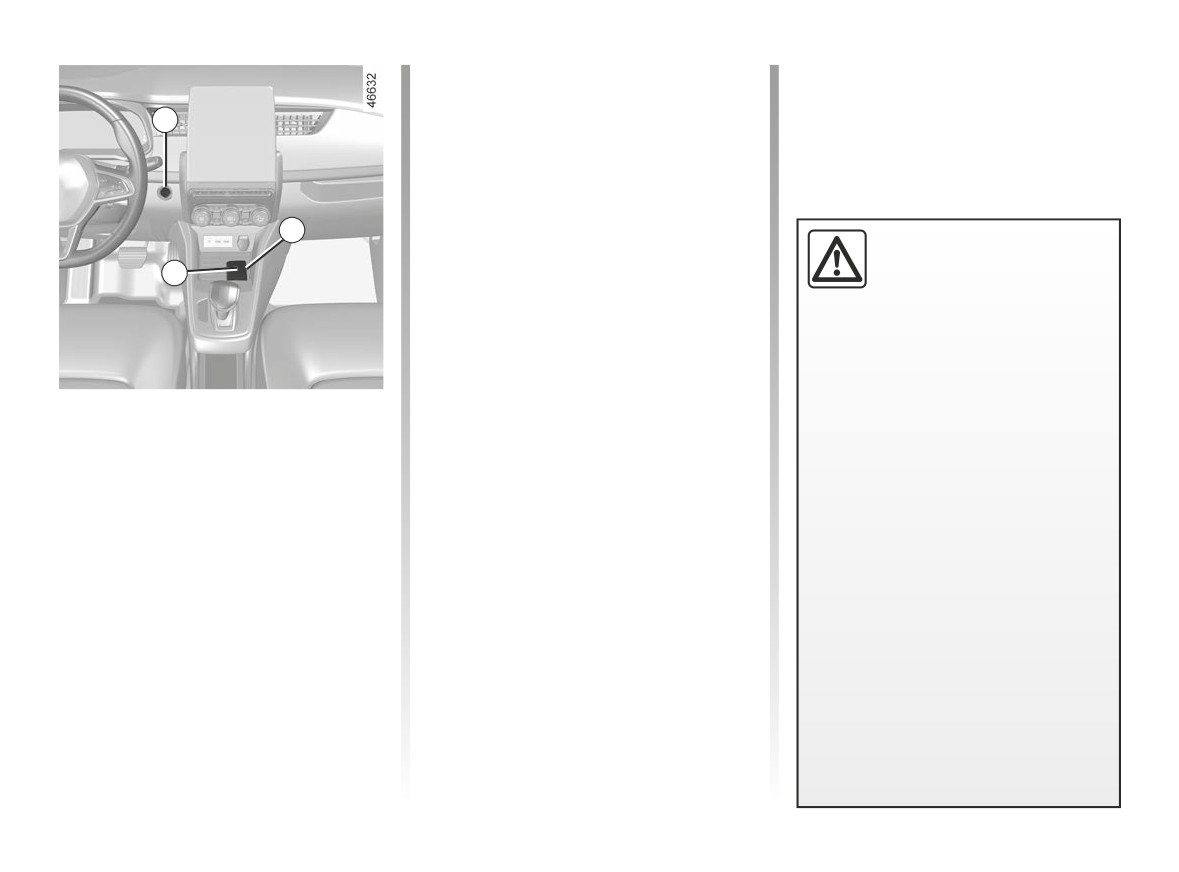
STARTING, STOPPING THE ENGINE (2/3)
Operating faults
In certain cases, the hands-free card
2
may not work:
- the card battery is flat, the secondary
12 V battery is discharged etc.;
- near to appliances operating on the
4
same frequency as the card (moni-
Driver’s responsibility
tor, mobile phone, video game, etc.);
when parking or stopping
3
- vehicle located in a high electromag-
the vehicle
netic radiation zone.
Never leave an animal,
The message “Place card on zone +
child or adult who is not self-suffi-
START” appears on the instrument
cient alone in your vehicle, even for
panel.
a short time.
“Hands-free” starting with the
Press the brake pedal, then place the
They may pose a risk to themselves
tailgate open
card 4 (button side) on the placement
or to others by starting the engine,
area 3. Press the 2 button to start the
activating equipment such as the
In this case, the card should not be lo-
vehicle. The message goes out.
electric windows or locking the
cated in the luggage compartment, to
doors, for example.
prevent the risk of loss.
Also, in hot and/or sunny weather,
Accessories function
please remember that the tempera-
(switching on the ignition)
ture inside the passenger compart-
ment increases very quickly.
Once you have gained access to your
vehicle, you may use some of its func-
RISK OF DEATH OR SERIOUS
tions (radio, navigation, wipers, etc.).
INJURY.
To use the other functions, with the
card in the passenger compartment,
press the 2 button without pressing the
pedals.
2.3
CarManuals2.co
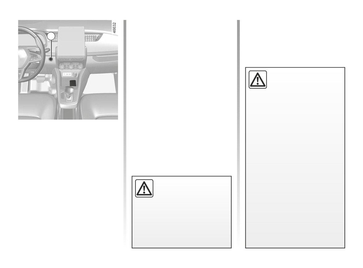
STARTING, STOPPING THE ENGINE (3/3)
If the card is no longer in the passen-
ger compartment or if the card’s battery
2
is dead, when the vehicle is stationary
and you try to switch the engine off,
the message “Keycard absent : press/
hold START” appears on the instrument
panel: press button 2 for longer than
three seconds.
With the engine switched off, any ac-
Driver’s responsibility
cessories being used (radio, etc.) will
when parking or stopping
continue to function for approximately
the vehicle
10 minutes.
Never leave an animal,
When the driver’s door is opened, the
child or adult who is not self-suffi-
accessories stop working.
cient alone in your vehicle, even for
a short time.
Stopping the engine
They may pose a risk to themselves
or to others by starting the engine,
The vehicle must be at a standstill.
activating equipment such as the
Press the 2 button: the engine stops,
electric windows or locking the
the READY message goes out on
doors, for example.
the instrument panel and the assisted
Also, in hot and/or sunny weather,
parking brake is applied. The steering
please remember that the tempera-
column is locked when the driver's door
ture inside the passenger compart-
is opened or the vehicle is locked.
ment increases very quickly.
Never switch off the igni-
RISK OF DEATH OR SERIOUS
tion before the vehicle has
INJURY.
stopped completely. Once
the engine has stopped, the
brake servo, power-assisted steer-
ing, etc., and the passive safety de-
vices such as the airbags and pre-
tensioners will no longer operate.
2.4
CarManuals2.co
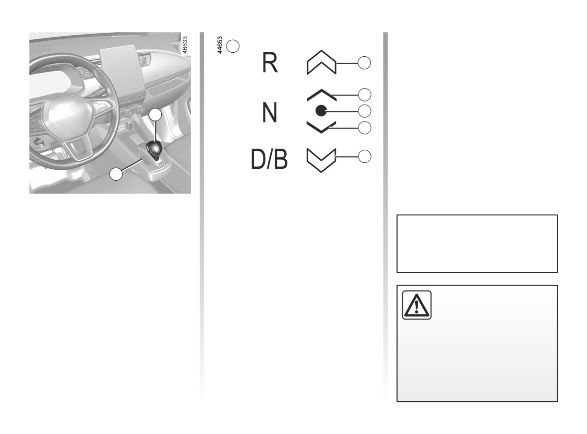
GEAR CONTROL (1/3)
Operation
B
With the engine running READY mes-
4
sage lit on the instrument panel ➥ 2.2,
the gear control is automatically in N
position.
3
To exit position N, it is essential to de-
press the front brake pedal.
2
1
With your foot on the brake pedal
3
(warning light c on display A goes
out), move the lever out of position N.
4
A
Selector lever 1
4: position accessible from the cur-
R: reverse.
rent position by moving the selec-
N: neutral.
tor lever 1 two notches forwards or
D: moving off forwards normally.
backwards.
The vehicle can only be started if
B: moving off forwards with strong
the charging cord is unplugged from
The 3 or 4 symbols are displayed to in-
regenerative braking.
the vehicle.
dicate the gears that can be selected. If
The A indicator light displays the gear
these symbols are absent this indicates
engaged.
that the gears cannot be selected from
the current position.
The following informative symbols may
Obstructions to the driver
appear on the instrument panel dis-
The required gear will flash on the in-
On the driver’s side, only
play B:
strument panel if a gear is not acces-
use mats suitable for the
sible from the engaged position of the
vehicle, attached with the
2: position of the gear engaged;
lever.
pre-fitted components, and check
3: position accessible from the cur-
the fitting regularly. Do not lay one
rent position by moving the selector
mat on top of another. There is a
lever 1 one notch forwards or back-
risk of wedging the pedals
wards;
2.5
CarManuals2.co
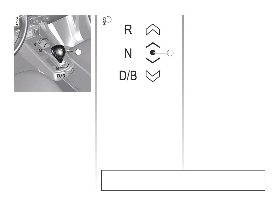
GEAR CONTROL (2/3)
Driving in mode B
B
This mode allows driving with a more
dynamic regenerative mode. When
releasing the accelerator, the vehicle
uses regenerative braking to slow down
the vehicle. Thus the motor generates
higher electrical current which allows
1
2
the traction battery to be recharged.
When you select position B when the
vehicle is stationary, the vehicle moves
forward as soon as you release the
brake pedal (without pressing on the
accelerator pedal).
In B mode, the regenerative braking will
be reduced if the accumulator is cold or
completely charged.
One-touch selector
Driving in mode D
Move the selector lever 1 one or two
When you select position D when the
Move from D position to B or
notches forwards or backwards to
vehicle is stationary, the vehicle moves
engage the desired position (R, N, D
forward as soon as you release the
B to D
or B) then release the lever and it will
brake pedal (without pressing on the
To switch from one position to the other,
return to a stable position.
accelerator pedal).
tilt the lever to one notch or two notches
While driving, press the accelerator
backwards.
The selected position is displayed on
pedal to achieve the desired speed.
The selected position, lit up on the in-
the instrument panel along with the 2
strument panel, alongside warning
warning light in front of the position.
light 2, will confirm the position of the
If certain conditions prevent shifting
gear control.
from one position to another, the re-
quested position flashes on the instru-
ment panel.
The last selected position (B or D) is stored and will be the first of the two posi-
tions accessible from the current position N or R.
2.6
CarManuals2.co
GEAR CONTROL (3/3)
To select reverse gear
Operating faults
With the vehicle stationary, engine run-
During driving:
ning, Nposition, D or B engaged, de-
- if the message “WARNING: Check
press the brake pedal and move for-
Gearbox” appears on the instrument
ward the lever by two notches, R lights
panel, this indicates a fault.
When the door is opened, the mes-
up on the instrument panel.
sage “Select NEUTRAL N” is dis-
Contact your approved Dealer as
The reversing lights will illuminate as
played on the instrument panel
soon as possible;
soon as reverse gear is selected (igni-
if the gear control is in a position
tion on) and, depending on the vehicle,
-
if the message “WARNING: Gearbox
other than N and the engine is not
the reversing camera ➥ 2.70.
Overheating” appears on the instru-
switched off.
ment panel, stop as soon as possi-
Note: with the engine running, the ve-
ble to allow the gearbox to cool down
hicle moving between 0 and 5 mph
In the event of an impact to
and wait for the message to disap-
(8 km/h) and position N or R engaged, it
the underside of the vehicle
pear.
is not necessary to depress the brake
(e.g.: striking a post, raised
pedal to engage the position D. This is
kerb or other street furni-
useful when parking manoeuvres re-
ture), this may result in damage to
quire alternating forward and reverse
the vehicle (e.g.: twisted axle), the
gearing.
electrical circuit or the traction bat-
tery.
Do not touch the circuit elements or
Parking the vehicle
any fluids or liquids.
With the vehicle stationary, stop the
To prevent any risk of accident,
engine. Neutral position is engaged
have your vehicle checked by an
and the electronic parking brake is ap-
authorised dealer.
plied automatically.
Risk of serious injury or electric
shock and risk to life.
The N position of the lever
does not mechanically lock
the drive wheels, make
sure it is immobilised before
leaving the vehicle.
2.7
CarManuals2.co
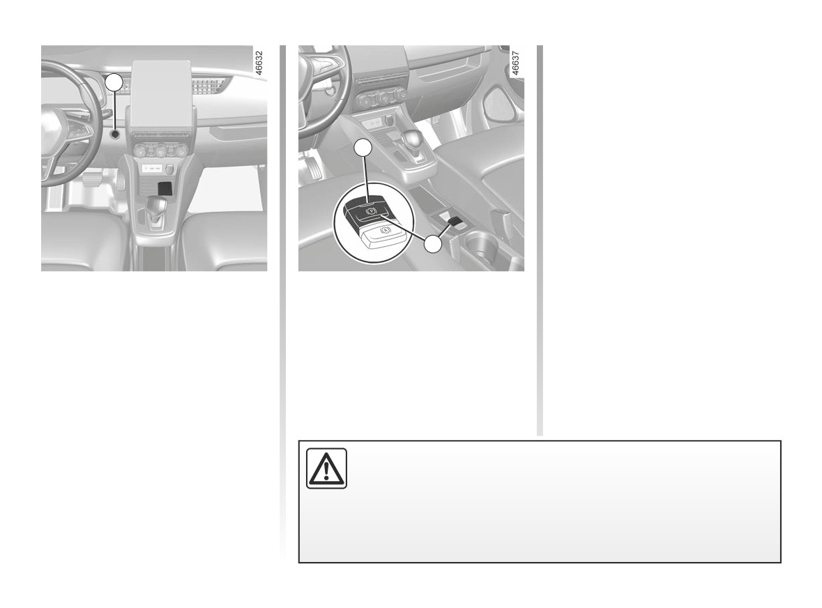
ELECTRONIC PARKING BRAKE (1/4)
To confirm that the electronic parking
brake is applied, the message “Parking
1
Brake ON” and warning light }
on the instrument panel and warning
light 2 on the switch 3 light up.
After the engine is switched off, indi-
2
cator light 2 goes out several minutes
after the assisted parking brake has
been applied and indicator light }
goes out when the vehicle is locked.
3
Assisted operation
Applying the electronic parking
brake
With the vehicle stationary, the elec-
tronic parking brake can be used to im-
mobilise the vehicle:
- by pressing the engine start/stop
button 1;
or
- when the driver’s seat belt is un-
fastened;
Before leaving the vehicle, check that the electronic parking brake is fully
or
applied. Warning light 2 on switch 3 and warning light }
on the in-
- when the driver’s door is opened;
strument panel light up to show that the parking brake is applied but go
or
out when the doors are locked.
– when the engine is stopped.
2.8
CarManuals2.co
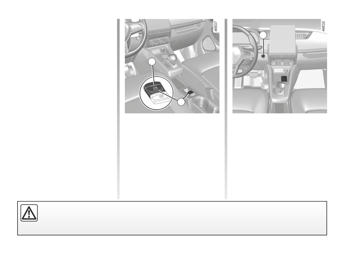
ELECTRONIC PARKING BRAKE (2/4)
Assisted operation
(continued)
1
Note: in some situations (electronic
parking brake failure, manual release of
the parking brake, etc.), a beep sounds
and the message “WARNING: Apply
Parking Brake” appears on the instru-
2
ment panel to warn you that the elec-
tronic parking brake has been released.
- with the engine running: when the
driver’s door is opened;
- with the engine off: when a front door
is opened.
3
In this case, pull and release switch 3 to
apply the assisted parking brake.
Manual operation
Manually releasing the electronic
Assisted release of the parking
parking brake
You can apply the electronic parking
brake
brake manually.
Press switch 1 without pressing the
The brake will be released as soon as
pedals to switch the ignition on. Press
the vehicle starts and accelerates.
Manually applying the electronic
the brake pedal then press switch 3: in-
parking brake
dicator light 2 on the switch and indica-
Pull switch 3. Warning light 2 and warn-
tor light }
displayed on the instru-
ment panel go out.
ing light }
on the instrument panel
light up.
Before leaving the vehicle, check that the electronic parking brake is fully applied. Warning light 2 on switch 3 and
warning light }
on the instrument panel illuminate to show that the parking brake is applied but switch off when
the doors are locked.
2.9
CarManuals2.co
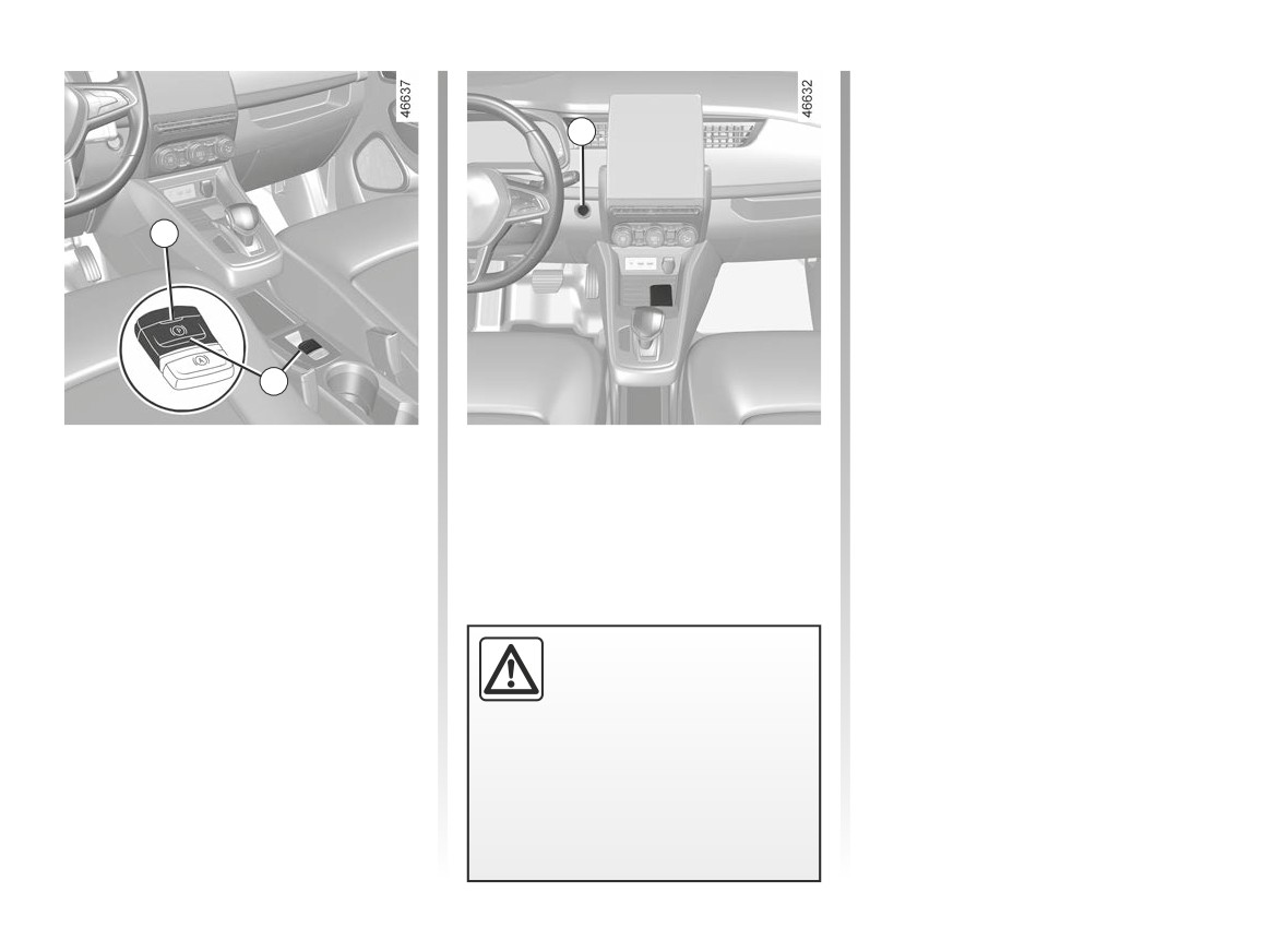
ELECTRONIC PARKING BRAKE (3/4)
To park, without applying the electronic
parking brake (if there is a risk of freez-
ing, for example):
1
- stop the engine by pressing the
engine Start/Stop button 1;
- release the driver’s seat belt;
2
- open the driver’s door;
- if necessary, position a chock in front
of or behind the wheels to ensure
that the vehicle is immobilised;
- manually release the electronic park-
ing brake (please see the informa-
3
tion on “Manually releasing the elec-
tronic parking brake” on the previous
Brief stop
Hill parking
page). The message “WARNING:
Apply Parking Brake” is displayed on
To apply the electronic parking brake
When parking on
a slope,
pull the
the instrument panel accompanied
manually (when stopping at a red light,
switch 3 for a few seconds to enable
by a beep to warn you that it is re-
or stopping when the engine is running,
maximum application of the parking
leased (this is normal);
etc.): pull and release the switch 3. The
brake.
brake is released as soon as the vehi-
- close the driver’s door and lock the
cle is started up again.
vehicle.
When parking on a slope
in conditions such as mud,
snow or ice, it is possi-
ble that the vehicle may
become displaced. Turn the wheels
so that the vehicle comes to rest
against a robust object (pavement
kerb, etc.).
2.10
CarManuals2.co

ELECTRONIC PARKING BRAKE (4/4)
Operating faults
For safety reasons, automatic release
is deactivated when the driver’s door
-
is open or not shut properly and the
light illuminates on the instrument
engine is running (in order to prevent
panel accompanied by the mes-
the vehicle from moving without the
sage “Check Parking Brake” and in
driver). The “Release Parking Brake
Manually” message appears on the
some cases the }
warning light
instrument panel when the driver de-
appears. Contact your approved
presses the accelerator.
Dealer straight away.
Never leave your vehicle
-
If there is an assisted parking brake
without moving the selec-
fault, the warning light
®
tor lever to position N, ap-
comes on, along with the message
plying the handbrake and
“WARNING: Braking System”, a
switching off the engine. This is be-
beep and, in some cases, the warn-
cause when the vehicle is stationary
with the engine running and a gear
ing light }
engaged, the vehicle may begin to
This means that you must stop as
move if you accelerate.
soon as traffic conditions allow.
There is a risk of accidents.
If the message “WARNING:
Electric System” or “Check
battery” is displayed, you
must immobilise the vehicle
by pulling the switch 3 for approxi-
If no lights or sounds are ap-
mately 10 seconds. If the slope and
parent, this indicates a fault
the conditions require it, chock the
in the instrument panel. This
wheels of the vehicle.
indicates that it is essential
Risk of loss of immobilisation of
to stop immediately (as soon as traf-
the vehicle.
fic conditions allow). Ensure that the
vehicle is correctly immobilised and
Call an approved Dealer.
contact an approved Dealer.
2.11
CarManuals2.co

ENVIRONMENT
Your vehicle has been designed with
Please make your own
Recycling
respect for the environment in mind for
contribution towards
Your vehicle is 85% recyclable and
its entire service life: during production,
protecting the environment
95% recoverable.
use and at the end of its life.
too.
To achieve these objectives, many of
- Worn parts replaced in the course
the vehicle components have been de-
Manufacture
of routine vehicle maintenance (sec-
signed to enable them to be recycled.
Your vehicle has been manufactured at
ondary 12 V battery, batteries, etc.)
The materials and structures have
an industrial site which uses a progress
must be disposed of through special-
been carefully designed to allow these
policy to reduce environmental impacts
ist organisations.
components to be easily removed and
on rivers and natural areas (reduc-
reprocessed by specialist companies.
- At the end of the vehicle’s service
tion of water and energy consumption,
life, it should be sent to approved
In order to preserve raw material re-
visual and noise pollution, atmospheric
centres to ensure that it is recycled.
sources, this vehicle incorporates nu-
emissions and waste water, sorting and
merous parts made from recycled plas-
reusing waste).
- In all cases, comply with local legis-
tics or renewable materials (vegetable
lation.
or animal-derived materials such as
cotton or wool).
2.12
CarManuals2.co
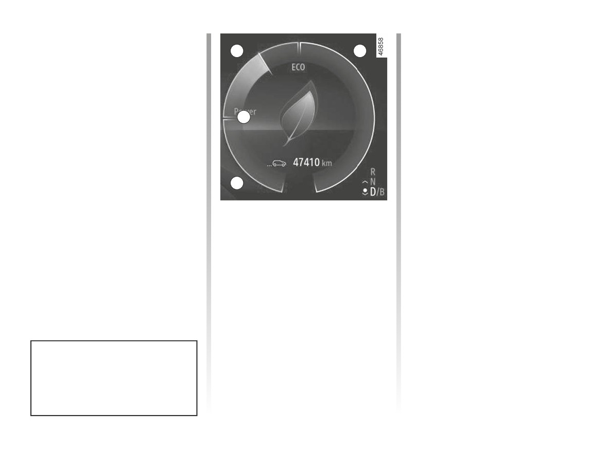
DRIVING ADVICE, ECO-DRIVING (1/3)
Consumption in real time depends on
Optimum use zone 0
vehicle usage conditions, equipment
B
C
Indicates nil consumption.
fitted and the user’s driving style. To op-
timise fuel consumption, please refer to
Green “recommended
the following advice.
consumption” B usage zone
Depending on the vehicle, you will be
The traction battery supplies the elec-
provided with functions which enable
trical energy required for the motor to
you to lower the energy consumption:
0
move the vehicle.
– charge meter;
- the driving style indicator;
“Consumption not recommended”
– the journey record and eco-driving
white use zone C
advice via the multimedia screen;
Indicates high energy consumption.
- ECO mode, activated by the ECO
button.
A
If fitted on the vehicle, the navigation
system provides additional information.
Charge meter
(on the instrument panel)
The charge meter gives the driver a
real-time view of the vehicle’s energy
consumption.
Blue “Energy recovery” A usage
zone
When driving, if you lift your foot off the
accelerator pedal or apply the brake,
the motor generates electrical current
during deceleration, and this energy is
used to slow down the vehicle and re-
charge the traction battery.
The presence and display of this in-
formation depends on the type of
ambiance selected ➥ 1.80.
2.13
CarManuals2.co
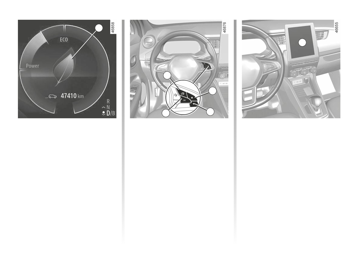
DRIVING ADVICE, ECO-DRIVING (2/3)
1
6
2
3
5
4
Driving style indicator
Press the 3 or 4 switch to access the
- an overall grade taking into account
indicator menu, then confirm by press-
acceleration, braking anticipation
Informs you about the driving style
ing 5 “OK”.
and your skill in managing speed;
adopted in real time. This is shown by
- advice to enable you to improve your
indicator light 1.
rating.
The more petals displayed on 1, the
Journey record
more your driving is flexible and eco-
For more information, refer to the equip-
For vehicles fitted with this, once the
nomical.
ment user guide.
engine is switched off, a Journey
If you regularly monitor this indicator,
Record is displayed on the multimedia
you will reduce your vehicle’s fuel con-
screen 6. This record shows the infor-
Navigation system
sumption.
mation relating to your last journey:
To activate/deactivate the driving style
Using the information available on your
- average energy consumption;
indicator, press switch 2 as many times
navigation system (traffic information,
- number of miles/kilometres travelled;
as necessary to reach the Data tab.
nearest charging station, etc.) makes it
easy to manage your journey.
2.14
CarManuals2.co
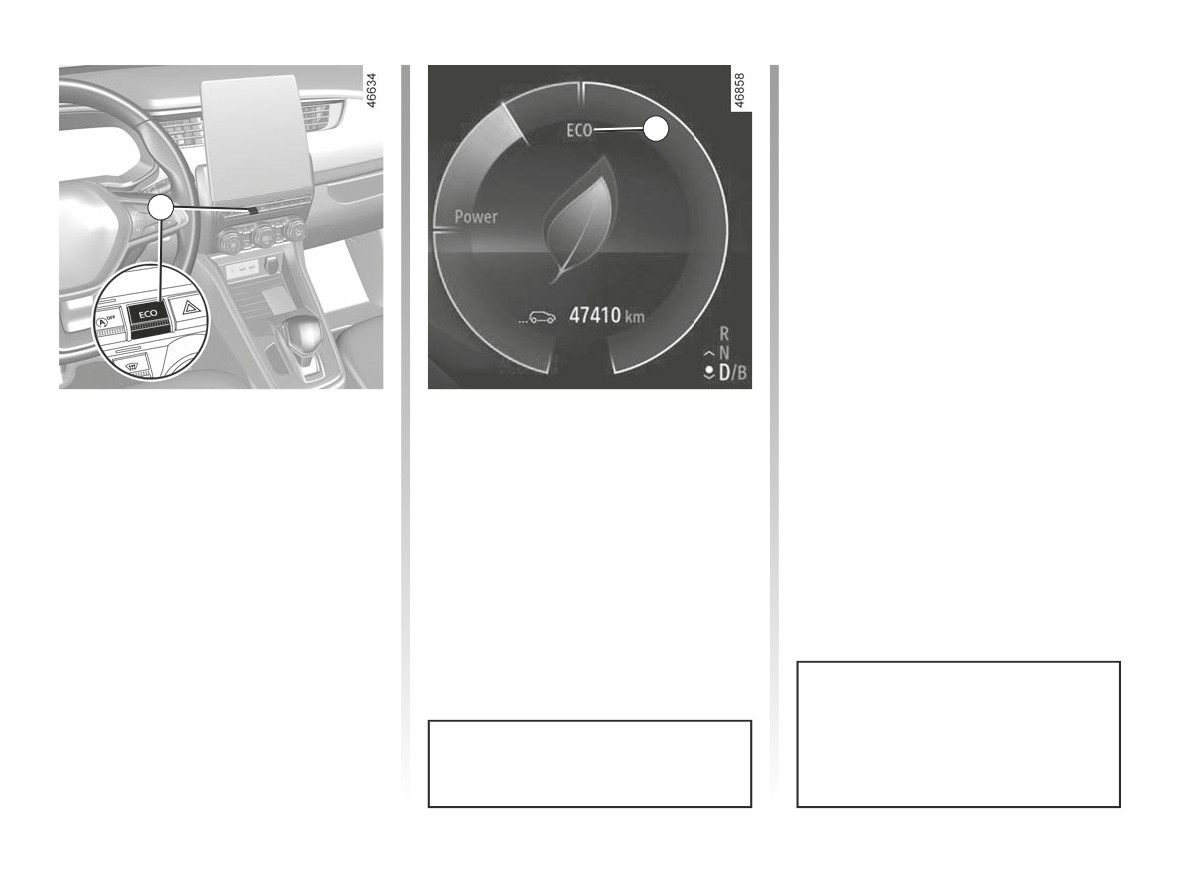
DRIVING ADVICE, ECO-DRIVING (3/3)
Disabling the function
Press the switch 7.
8
Warning light 8 ECO goes out on the
instrument panel.
7
ECO mode
While driving, it is possible to exit the
ECO mode temporarily in order to im-
ECO mode is a function which opti-
prove engine performance.
mises vehicle range. It affects certain
driving operations (acceleration, cruise
To do this, press the accelerator pedal
control, deceleration, etc.).
firmly and fully. The warning light 8 ECO
flashes on the instrument panel for the
Activating the function
duration of the operation.
Press the switch 7.
ECO mode is reactivated when you
take pressure off the accelerator pedal.
The 8 ECO warning light comes on on
the instrument panel.
Cruise control switches to standby
each time ECO mode is activated or
With ECO mode on, the vehicle
deactivated ➥ 2.57.
speed is limited to approximately
62 mph (100 km/h).
2.15
CarManuals2.co
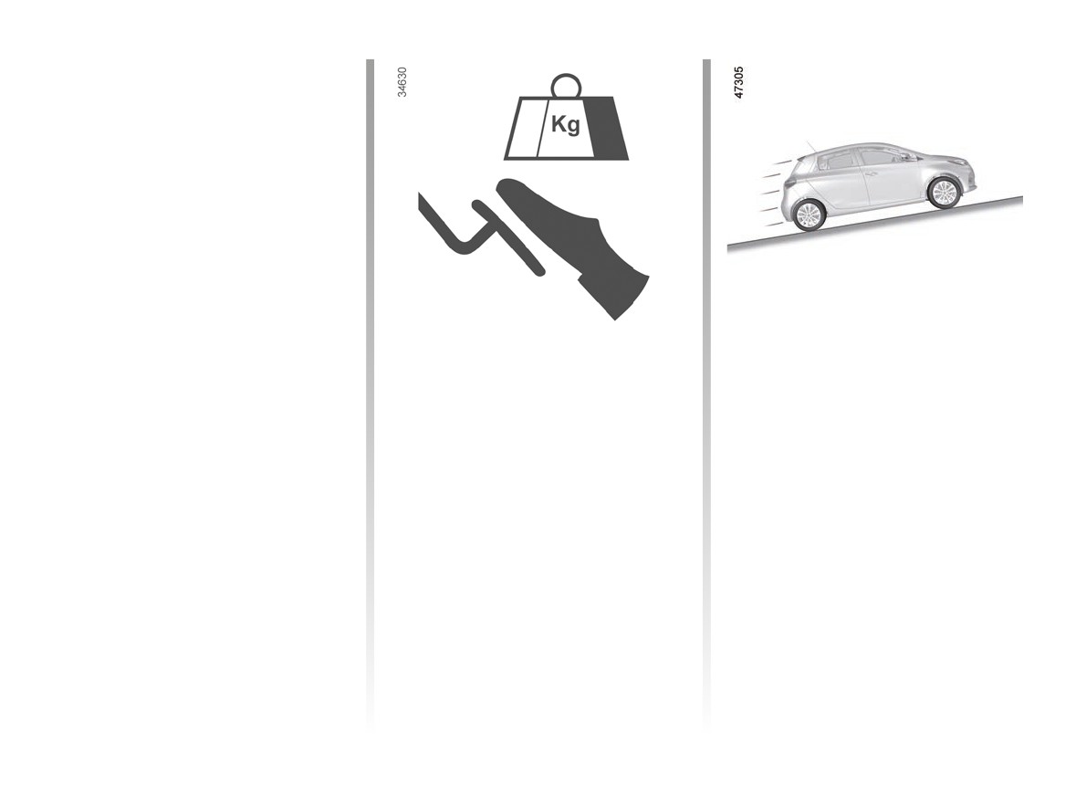
VEHICLE RANGE: recommendations (1/2)
In real usage, the range of an electric
vehicle may vary depending on several
factors over which you have partial con-
trol, which may make a considerable
difference to the vehicle range. These
factors are:
- speed and driving style;
- type of road;
- heating level;
- tyres;
- use of electrical accessories;
- vehicle loading.
Furthermore, activating ECO mode en-
ables the vehicle to automatically take
charge of all energy consumers (engine
power etc.) to reduce their consumption
to the fullest possible extent ➥ 2.13.
-
reducing the speed from approx-
-
adapt your driving style to avoid ex-
imately
55.8 mph
(90 km/h) to
cessive energy consumption;
49.6 mph (80 km/h) allows you to
Speed and driving style
-
favour power recovery: anticipate
save up to around 10% of fuel range.
traffic changes by lifting your foot off
Driving at high speed will significantly
A “sporty” driving style reduces your
the accelerator pedal or by braking
reduce your vehicle’s range. Examples
vehicle range: opt for a “lighter” driving
gradually.
(at a steady speed):
style.
- reducing the speed from approx-
Advice:
Road type
imately
80.6 mph (130 km/h) to
68.2 mph (110 km/h) allows you to
- drive at a constant speed;
Do not try to maintain the same speed
save up to around 20% of fuel range;
up a hill, accelerate no more than you
- keep an eye on the tools available
to you to view the road conditions
would on the level. Keep your foot in
(charge meter, current consumption,
the same position on the accelerator
journey record, etc.) ➥ 2.13 ;
pedal.
2.16
CarManuals2.co
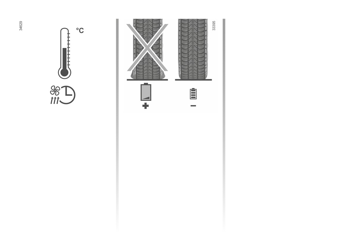
VEHICLE RANGE: recommendations (2/2)
Vehicle loading
Avoid pointlessly overloading your ve-
hicle.
Heating levels
Tyres
The use of heating or air-conditioning
An under-inflated tyre increases energy
reduces vehicle range.
consumption. Comply with the speci-
To maintain your vehicle range, you are
fied tyre pressures for your vehicle.
recommended to select “programming”
When driving, use tyres made by the
mode before using the vehicle ➥ 3.11.
same manufacturer, with the same di-
mensions, type and structure as the
original tyres. The use of non-regula-
tion tyres significantly reduces vehicle
range ➥ 4.9.
2.17
CarManuals2.co
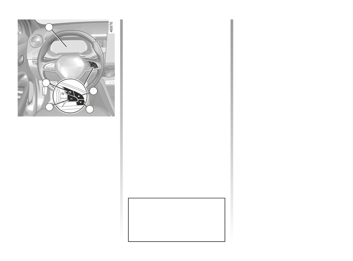
TYRE PRESSURE MONITOR (1/5)
Resetting the standard level
Resetting procedure
1
for the tyre pressures
Ignition on, vehicle stopped:
- Repeatedly tap switch 5 as many
This should be done:
times as necessary to reach the ve-
- when the standard tyre pressure
hicle tab;
needs to be changed to adapt to
- tap switch 2 or switch 3 to access
usage conditions (empty, carrying a
the tyre pressures reset page. The
load, motorway driving, etc.);
message “SET tyre pressure (press
- after swapping a wheel (however
and hold)” appears on the instrument
this practice is not recommended);
panel;
5
- after changing a wheel.
- press and hold the 4 OK switch to
2
It should always be done after checking
launch the reset. The flashing tyres
the tyre pressure of all four tyres when
symbol followed by the message
cold.
“Learning Tyre Pressures” indicates
4
3
Tyre pressures must correspond to the
that the reset request for the tyre
current usage of the vehicle (empty,
pressure has been acknowledged.
If the vehicle is equipped with the func-
carrying a load, motorway driving, etc.).
Reset can take several minutes of driv-
tion, this system monitors the tyre pres-
sure.
ing.
Note: the standard tyre pressure
cannot be less than that recommended
Operating principle
and indicated on the door frame.
Each wheel (except for the emergency
spare wheel) has a sensor in the infla-
tion valve which periodically measures
the tyre pressure.
The system displays the current pres-
sures on the instrument panel 1 and
alerts the driver in the event of insuffi-
cient pressure.
Resetting can also be performed
from the multimedia screen. Select
“Vehicle”, “Tyre pressure”.
2.18
CarManuals2.co
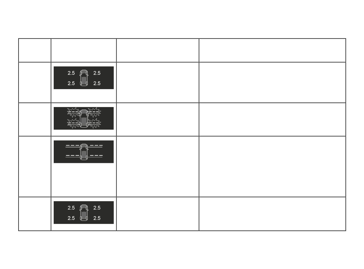
TYRE PRESSURE MONITOR (2/5)
The table below shows the possible messages related to the tyre resetting procedure.
Steps
Displays
Messages
Readings
(depending on
the vehicle)
1
Tyre pressure init. long press
With the ignition on and the vehicle stationary, start the
resetting the pressure of all four tyres by pressing and
holding the 4 OK switch.
2
Learning Tyre Pressures
The “---” quote marks in front of each wheel will flash to
indicate that the system has registered the tyre pressure
reset for all four wheels.
3
Tyre detection in progress
The “---” quote marks in front of each wheel will remain
lit. This system resets the tyre pressure of all four tyres.
You can now drive. The message may remain displayed
during short journeys.
Note: during the reset, tyre pressure monitoring remains
in operation.
4
The pressure value of the four tyres is displayed: the re-
setting procedure is complete and successful.
2.19
CarManuals2.co
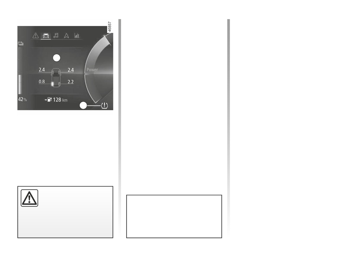
TYRE PRESSURE MONITOR (3/5)
“Adjust tyre pressure”
“Puncture”
A yellow wheel appears accompanied
A red wheel appears accompanied by
by a fixed 6
warning light and the
a fixed 6
warning light and the
message “Adjust Tyre Pressure”.
message “Puncture” as well as a sound
They indicate that a wheel is deflated.
signal.
Check and, if necessary, readjust the
This message appears along with the
A
pressures of the four wheels when cold.
®
warning light.
They indicate that the affected wheel
The warning light 6
goes off after
is punctured or severely underinflated.
a few minutes’ driving.
Replace it or contact an approved
dealer if it is punctured. Top up the tyre
pressure if the wheel is deflated.
6
“Check tyre pressure sensors”
The wheel disappears and the warning
Display
light 6
flashes for several sec-
The display A and the warning light 6
onds before staying on and the mes-
sage “Check Tyre Pressure Sensors”
on the instrument panel warn
appears.
you of any tyre pressure faults (flat tyre,
punctured tyre, system fault, etc.).
This message appears along with the
warning light. They indicate
that at least one wheel is not fitted
with sensors (e.g. emergency spare
wheel). Otherwise, consult an author-
ised dealer.
For your safety, the warning
light
®
requires you
to stop immediately as soon
as traffic conditions allow.
The sudden loss of pressure in a
tyre (burst tyre, etc.) cannot be de-
tected by the system.
2.20
CarManuals2.co

TYRE PRESSURE MONITOR (4/5)
“Tyre location failure”
Replacing wheels/tyres
Tyre repair product and
The message “Failure to detect tyres”
This system requires specific equip-
inflation kit
appears during driving if one or more
ment (wheels, tyres, hubcaps, etc.).
As the valves are specifically designed,
wheels have been fitted with sensors
➥ 5.6.
only use equipment approved by the
not recognised by the network.
Contact an approved Dealer to fit new
approved network. ➥ 5.3.
tyres and to find out about available ac-
Consult an approved dealer
cessories compatible with the system
and available from your dealer net-
Readjustment of tyre
work: the use of any other accessory
pressures
could affect the correct operation of the
system or damage a sensor.
The pressures must be adjusted
when the tyres are cold ➥ 4.9. If
the tyre pressures cannot be checked
Emergency spare wheel
when the tyres are cold, the recom-
If the vehicle is equipped with an emer-
mended pressures should be increased
gency spare wheel, it will not have a
by 0.2 to 0.3 bar (3 PSI).
sensor. If the vehicle is fitted with one,
Never deflate a hot tyre.
the warning light 6
flashes for
several seconds then comes on con-
tinuously along with the
warn-
ing light, and the message “Check Tyre
Pressure Sensors” appears on the in-
This function is an
addi-
strument panel.
tional driving aid.
However, the function is
not intended to replace the
driver. It cannot, therefore, under
any circumstances replace the vig-
ilance or the responsibility of the
driver. Check the tyre pressures, in-
cluding the emergency spare wheel,
once a month.
2.21
CarManuals2.co
TYRE PRESSURE MONITOR (5/5)
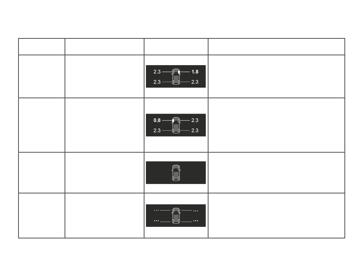
The information on the instrument panel signals any potential tyre pressure faults (e.g. deflated or punctured tyre). For
your safety, the warning light® requires you to stop immediately as soon as traffic conditions allow.
Indicator
Messages
Displays
Readings
lights
The wheel and associated pressure value are dis-
played in yellow.
Adjust Tyre Pressure
This indicates that tyre under-inflation has been de-
tected. Check and adjust the pressure of the four
tyres then reset the system.
The wheel and associated pressure value are dis-
played in red.
This indicates that the tyre concerned is punctured
Puncture
or severely underinflated. Adjust the pressure of the
+®
four tyres while cold and reset the system if the tyre
is deflated. Replace the tyre (or have it replaced) if
it is punctured.
A wheel is no longer displayed.
This indicates that at least one wheel is not fitted with
Check Tyre Pressure Sensors
a sensor (e.g. emergency spare wheel) or that the
sensor is faulty. Consult an approved dealer.
This indicates that the system has not been able to
determine the pressure of each tyre. This may be
Failure to detect tyres
caused by the use of a sensor not recommended by
an approved dealer. The tyre pressure sensor moni-
toring system remains in operation.
2.22
CarManuals2.co
ACTIVE EMERGENCY BRAKING (1/7)
Depending on the reactivity of the
1
driver, the system can assist with brak-
ing in order to limit damage or prevent
a collision.
Note: ensure that the windscreen and
front bumper are not obstructed (by
dirt, mud, snow, condensation, number
plate, etc.).
2
This system can apply maximum
braking to the vehicle until it is
completely stationary if necessary.
For safety reasons, always wear
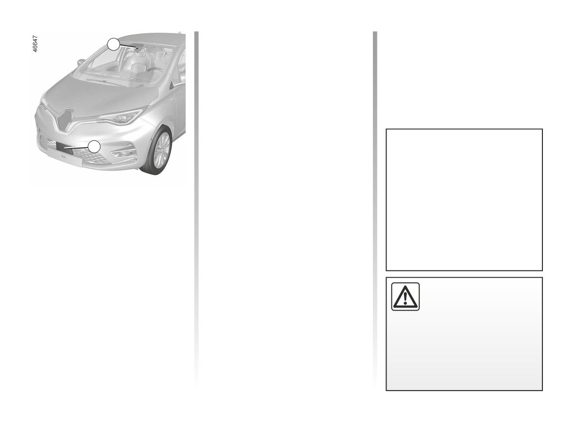
The system uses information from the
your seat belt when travelling in
radar 2 and the camera 1 to determine
your vehicle and make sure that it
the distance from your vehicle:
is loaded so that no items can be
- from the vehicle ahead in the same
thrown forward and hit the occu-
lane;
pants.
or
- surrounding pedestrians and cy-
clists.
This function is an addi-
The system informs the driver if there
tional driving aid. This func-
is a risk of head-on collision to enable
tion is not under any circum-
appropriate emergency manoeuvres
stances intended to replace
(pressing the brake pedal and/or turn-
the due care and attention of the
ing the steering wheel).
driver, who should at all times be
in control of the vehicle.
2.23
CarManuals2.co
ACTIVE EMERGENCY BRAKING (2/7)
Operation
Special features of warnings
3
Depending on the speed, the warning
Detection of vehicles
and braking may be activated simulta-
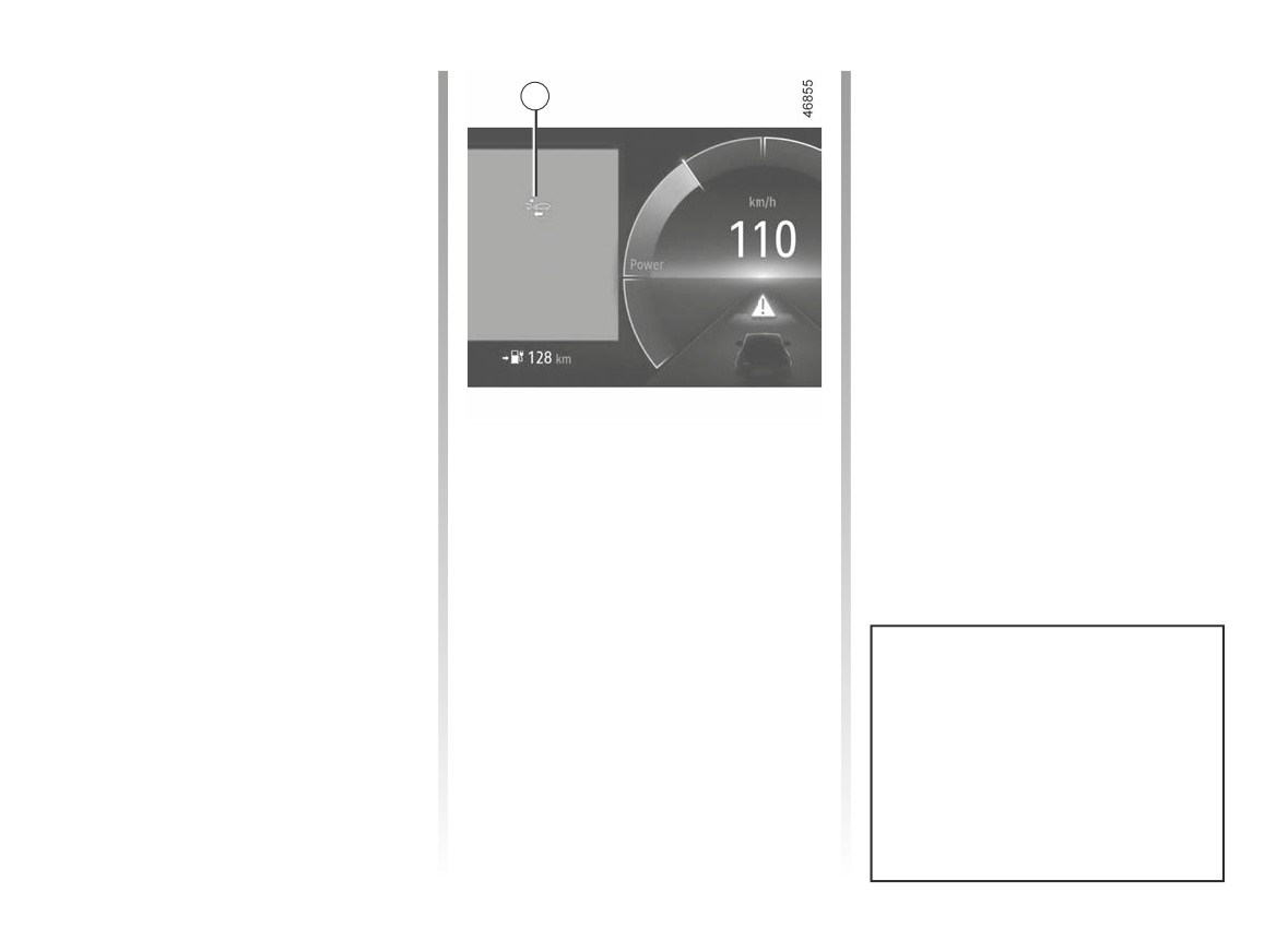
When driving, in the event of a risk of
neously.
collision with the vehicle in front the
system will:
Special features of stationary
- warn of the risk of collision: when
vehicles
the vehicle speed is between 4 mph
Stationary vehicles are detected when
(7 km/h) and 106 mph (170 km/h),
your vehicle is being driven at a speed
the message “Brake” is displayed
between approximately 4 mph (7 km/h)
in red on the instrument panel 3 ac-
and 50 mph (80 km/h). The system is
companied by an audible warning.
not active and does not emit a warning
If the driver depresses the brake
for stationary vehicles when you exceed
pedal and the system still detects a
approximately 50 mph (80 km/h).
risk of collision, the brake force is in-
creased.
If the vehicle stopped as a result of
- braking may be triggered: when
active emergency braking, the driver
the vehicle is moving slower than ap-
must keep the vehicle stationary by ap-
proximately 75 mph (120 km/h), if the
plying the brake pedal.
driver does not respond to the warn-
Note: if the driver uses the vehicle con-
ing and a collision becomes immi-
trols (steering wheel, pedals, etc.) the
nent.
system may delay certain operations or
not activate.
In the event of emergency manoeu-
vre, you can stop braking at any
moment by:
- tapping the accelerator pedal;
or
- turning the steering wheel as a
collision avoidance manoeuvre.
2.24
CarManuals2.co
ACTIVE EMERGENCY BRAKING (3/7)
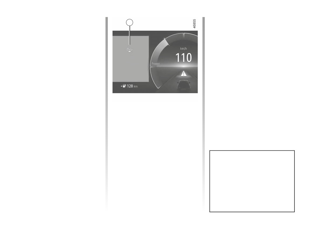
Detection of pedestrians and
Special features of warnings
3
cyclists
Depending on the speed, the warning
(depending on the vehicle)
and braking may be activated simulta-
When driving at a speed between
neously.
approximately
4 mph (7 km/h) and
50 mph (80 km/h), if there is a risk of
collision with a pedestrian or a cyclist,
the system:
- warns you of a collision risk:
the “Brake” message is displayed in
red on the instrument panel 3, ac-
companied by a sound signal.
If the driver presses the brake pedal
and the system still detects a risk
of collision, the braking force is in-
creased if it is not sufficient to pre-
If active emergency braking has caused
vent the collision.
the vehicle to stop, the vehicle is kept
stationary for a short time. Beyond this
- may trigger braking:
time limit, the vehicle must be held sta-
if the driver fails to react following
tionary by the driver keeping their foot
the alert and collision becomes im-
on the brake pedal.
minent.
Note: if the driver uses the vehicle con-
trols (steering wheel, pedals, etc.) the
system may delay certain operations or
not activate.
In the event of emergency manoeu-
vre, you can stop braking at any
moment by:
- tapping the accelerator pedal;
or
- turning the steering wheel as a
collision avoidance manoeuvre.
2.25
CarManuals2.co
ACTIVE EMERGENCY BRAKING (4/7)
Temporarily not available
Operating faults
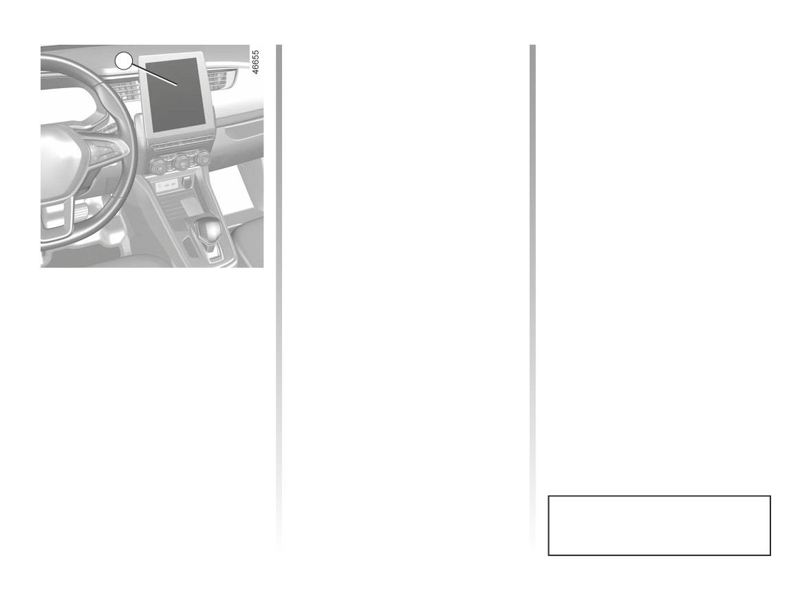
4
If the system detects a temporary
If the function detects an operating
fault the
warning light illumi-
fault, the
and
warning
nates, or depending on the vehicle the
lights or, depending on the vehicle, the
warning light illuminates on the
warning light illuminate(s) on
instrument panel.
the instrument panel accompanied by
the message “Front camera to check”
The possible causes are:
or “Front radar to check” or “Check
- the system is temporarily blinded
Camera/Radar”.
(glare from the sun, dipped beam
Consult an approved dealer.
headlights, bad weather conditions
etc.). The system will be operational
again when visibility conditions are
better;
Activating or deactivating the
- the system is temporarily interrupted
system
(e.g. the windscreen, front or rear
bumper or logo is obscured by dirt,
For vehicles fitted with a multimedia
mud, snow, condensation, etc.) In
screen
this case, park the vehicle and switch
off the engine. Clean the windscreen,
With the vehicle stopped and the engine
the front bumper or the logo. When
running, from the multimedia screen 4,
you next start the engine, the warn-
select “Settings” menu, “Vehicle” tab,
ing light and the message go out.
“Driving assistance” menu,
“Active
braking” then select “ON” or “OFF”.
If this is not the case, this may arise from
another cause; contact an Approved
Upon deactivation of the system, the
Dealer.
warning light illuminates or, de-
pending on the vehicle, the
warning light illuminates on the instru-
ment panel.
This system is reactivated each time
the ignition is switched on.
2.26
CarManuals2.co

ACTIVE EMERGENCY BRAKING (5/7)
Active emergency braking
This function is an additional driving aid. This function is not under any circumstances intended to replace the due care
and attention of the driver, who should at all times be in control of the vehicle. The triggering of this function may be
delayed or prevented when the system detects clear signs of control of the vehicle by the driver (action on the steer-
ing wheel, pedals etc.).
The system cannot be activated:
- when the gear lever is in neutral position or the clutch pedal has been depressed for ten seconds;
- when the parking brake is activated;
- when the Electronic Stability Program (ESC) has started.
System servicing/repairs
- In the event of an impact, the radar and/or camera may become misaligned and their service may be affected. Deactivate
the function and contact an Approved Dealer.
- Any work in the area where the radar and/or camera is located (repairs, replacements, windscreen modifications, etc.) must
be carried out by a qualified professional.
Only an authorised dealer is qualified to service the system.
2.27
CarManuals2.co

ACTIVE EMERGENCY BRAKING (6/7)
System disturbance
Some conditions can disturb or damage the operation of the system, such as:
- a complex environment (metal bridge, tunnel etc.);
- poor weather conditions (snow, hail, black ice etc.);
- poor visibility (night, fog etc.);
- poor contrast between the object (vehicle, pedestrian etc.) and the surrounding area (e.g. pedestrian dressed in white lo-
cated in a snowy area etc.);
- being dazzled (glaring sun, lights of vehicles travelling in the opposite direction etc.);
- windscreen obscured (by dirt, ice, snow, condensation etc.);
- ...
In these conditions, the system may not react or may brake inadvertently.
Limitation of the system operation
- Each time the vehicle is started, the system carries out a calibration according to the vehicle surroundings and may be inac-
tive for a length of time between approximately two and five minutes;
- A vehicle travelling in the opposite direction will not trigger any alert or affect operation of the system;
- The radar and camera zones must be kept clean and free of any tampering in order to ensure the proper operation of the
system;
- The system may not respond to small vehicles such as motorbikes as effectively as to other vehicles;
- The system may not operate optimally when the road surface is slippery (rain, snow, black ice etc.);
- To ensure correct operation, the system needs to distinguish the complete outline of the pedestrian. So the system cannot
detect:
- pedestrians in the darkness or in poor lighting conditions;
- partially visible pedestrians:
- pedestrians less than approximately 80 cm tall;
- pedestrians carrying large objects;
- ...
In these conditions, the system may not react or may brake inadvertently.
2.28
CarManuals2.co

ACTIVE EMERGENCY BRAKING (7/7)
Deactivating the function
You must disable the function if:
- the brake lights are not functioning;
- the camera area has been damaged (e.g. on the inside or outside of the windscreen);
- the front of the vehicle was damaged (impact, distortion, scratch on the radar etc.);
- the vehicle is being towed (breakdowns);
- the windscreen is cracked or distorted (do not carry out windscreen repairs in this area; have it changed by an approved
dealer);
- you are not driving on a paved road.
In the event of the system behaving abnormally, deactivate it and consult an authorised dealer.
Halting the function
You can halt the active braking function at any time by tapping the accelerator pedal or by turning the steering wheel in a col-
lision avoidance manoeuvre.
2.29
CarManuals2.co

DRIVER CORRECTION DEVICES, AIDS (1/5)
Depending on the vehicle, they com-
ABS (anti-lock braking
prise:
system)
– the ABS
(anti-lock braking
Under heavy braking, the ABS prevents
system);
the wheels from locking, allowing the
- the electronic stability program
stopping distance to be managed and
ESC with understeer control and
keeping control of the vehicle.
traction control;
Under these circumstances, the vehi-
cle can be steered to avoid an obstacle
- emergency braking assistance
whilst braking. In addition, this system
with (depending on the vehicle)
can increase stopping distances, par-
braking anticipation;
ticularly on roads with low surface grip
- hill start assist;
(wet ground etc.).
You will feel a pulsation through the
- regenerative braking system.
These functions are an ad-
brake pedal each time the system is
Other driving assistance systems are
ditional aid in the event of
activated. The ABS does not in any way
detailed on the following pages.
critical driving conditions,
improve the vehicle’s physical perform-
enabling the vehicle behav-
ance relating to the road surface and
iour to be adapted to suit the driving
roadholding. It is still essential to follow
conditions.
the rules of good driving practice (such
as driving at a safe distance from the
However, the functions do not take
vehicle in front etc.).
the place of the driver. They do
not increase the vehicle’s limits
and should not encourage you
to drive more quickly. Therefore,
they can under no circumstances
replace the vigilance or responsibil-
ity of the driver when manoeuvring
the vehicle (the driver must always
In an emergency, apply firm and
be ready for sudden incidents which
continuous pressure to the brake
may occur when driving).
pedal. There is no need to pump
it repeatedly. The ABS will modu-
late the force applied in the braking
system.
2.30
CarManuals2.co

DRIVER CORRECTION DEVICES, AIDS (2/5)
Operating faults
Electronic stability program
Understeer control
ESC with understeer control
This system optimises the action of the
-
and x
are lit on the in-
and traction control
ESC in the case of pronounced under-
strument panel accompanied, de-
steer (loss of front axle road holding).
pending on the vehicle, by the mes-
Electronic stability control ESC
sages “Check ABS”, “WARNING:
Traction control
This system helps you to keep control
Check Braking System” and “Check
of the vehicle in critical driving condi-
This system helps to limit wheelspin of
ESC”: the ABS, the ESC and the
tions (avoiding an obstacle, loss of grip
the drive wheels and to control the ve-
emergency brake assist are deacti-
on a bend, etc.).
hicle when pulling away accelerating or
vated. Braking is always enabled;
decelerating.
Operating principle
- x
, D
,
and
®
Operating principle
lit on the instrument panel accom-
A sensor in the steering wheel detects
Using the wheel sensors, the system
panied by the message “Braking
the direction selected by the driver.
measures and compares the speed of
system fault”: this indicates a fault
Other sensors throughout the vehicle
the drive wheels at all times and slows
in the braking system.
measure the actual direction.
down their over-rotation. If a wheel is
In both cases, please consult an
starting to slip, the system brakes au-
The system compares driver input to
Authorised Dealer.
tomatically until the drive supplied be-
the actual trajectory of the vehicle and
comes compatible with the level of grip
corrects the trajectory if necessary by
under the wheel again.
controlling the braking of certain wheels
and/or engine power. In the event that
the system is engaged, indicator light
flashes on the instrument panel.
Your braking systems
are partially operational.
However, it is dangerous
to brake suddenly and
it is essential to stop immediately,
as soon as traffic conditions allow.
Contact an approved dealer.
2.31
CarManuals2.co

DRIVER CORRECTION DEVICES, AIDS (3/5)
Operating faults
Brake lights come on
When the system detects an operat-
Depending on the vehicle, these may
ing fault the message “Check ESC” and
flash in the event of sudden decelera-
tion.
appear
on the instrument panel. In this case,
Braking anticipation
the ESC and traction control system
Depending on the vehicle, when you
are deactivated.
rapidly release the accelerator, the
Consult an approved dealer.
system anticipates the braking ma-
noeuvre in order to reduce stopping
distances.
Emergency brake assist
This system supplements the ABS
Special cases
and helps reduce vehicle stopping dis-
These functions are an ad-
When using the cruise control:
tances.
ditional aid in the event of
- if you use the accelerator, when you
release it, the system may be trig-
critical driving conditions,
Operating principle
gered;
enabling the vehicle behav-
The system is for detecting an emer-
- if you do not use the accelerator, the
iour to be adapted to suit the driving
gency braking situation. In this case,
system will not be triggered.
conditions.
the braking system immediately devel-
These functions do not take the
ops maximum power and may trigger
Operating faults
place of the driver. They do not
ABS regulation.
When the system detects an operating
increase the vehicle’s limits and
ABS braking is maintained as long as
fault the message “WARNING: Check
should not encourage you to
the brake pedal is applied.
Braking System” appears on the instru-
drive more quickly. Therefore,
they can under no circumstances
ing light.
replace the vigilance or responsibil-
ity of the driver when manoeuvring
Consult an approved dealer.
the vehicle (the driver must always
be ready for sudden incidents which
may occur when driving).
2.32
CarManuals2.co

DRIVER CORRECTION DEVICES, AIDS (4/5)
Hill start assistance
Depending on the gradient of the in-
cline, this system assists the driver
when starting on a hill. It prevents the
vehicle from rolling backwards by au-
The hill start assistance
tomatically applying the brakes when
system cannot completely
the driver lifts his/her foot off the brake
prevent the vehicle from
pedal to depress the accelerator pedal.
rolling backwards in all sit-
System operation
uations (extremely steep gradients,
etc.).
It only operates when the gear lever is
in a position other than N and the ve-
In all cases, the driver may depress
hicle is completely stationary (brake
the brake pedal to prevent the vehi-
pedal depressed).
cle from rolling backwards.
The system holds the vehicle for ap-
The hill start assistance function
proximately 2 seconds. The brakes are
should not be used for prolonged
then gradually released (the vehicle will
stops: use the brake pedal.
move according to the slope).
This function is not designed to im-
mobilise the vehicle permanently.
If necessary, use the brake pedal to
stop the vehicle.
The driver must remain particularly
vigilant when driving on slippery or
low-grip surfaces.
Risk of serious injury.
2.33
CarManuals2.co

DRIVER CORRECTION DEVICES, AIDS (5/5)
Regenerative braking system
Operating faults
When braking, the regenerative brak-
-
lights up on the instru-
ing system can convert the energy pro-
ment panel, alongside the mes-
duced by the vehicle deceleration into
sage “WARNING: Check Braking
electric energy.
System”: braking assistance is
available at all times.
This will recharge the 400 V traction
battery and provide greater vehicle
Under these conditions, the feel of
range.
applying the brake pedal may be dif-
ferent.
You are recommended to apply
strong continuous pressure to the
pedal.
Please see an authorised dealer.
-
®
lit on the instrument panel ac-
companied by the message “Braking
system fault”: this indicates a fault
in the braking system.
Please call an authorised dealer.
The
®
warning light
requires you to stop imme-
diately, for your own safety,
as soon as traffic conditions
allow. Switch off the engine and
do not restart it. Call an approved
Dealer.
2.34
CarManuals2.co
LANE DEPARTURE WARNING (1/4)
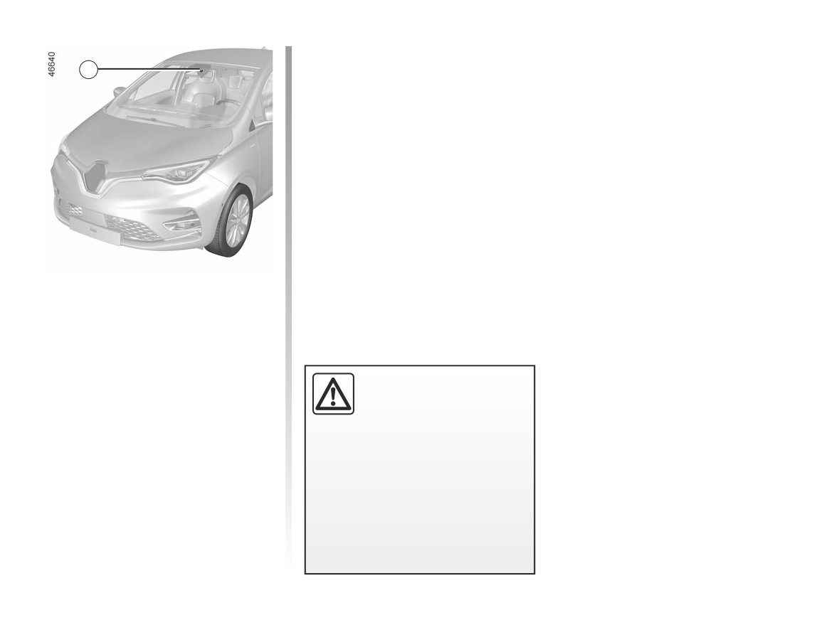
1
Using information from the 1 camera,
the function warns the driver when a
continuous or broken line is crossed
or when approaching the roadside (di-
vider, barrier, pavement, embankment,
etc.) without the direction indicator
lights being activated.
This function is an addi-
Note: make sure the windscreen is not
tional driving aid. This func-
obscured (dirt, mud, snow, condensa-
tion is not under any cir-
tion etc.).
cumstances intended to
replace the due care and attention
of the driver, who should at all times
be in control of the vehicle.
The lane departure warning func-
tion does not correct the vehi-
cle’s trajectory.
2.35
CarManuals2.co
LANE DEPARTURE WARNING (2/4)
Operation
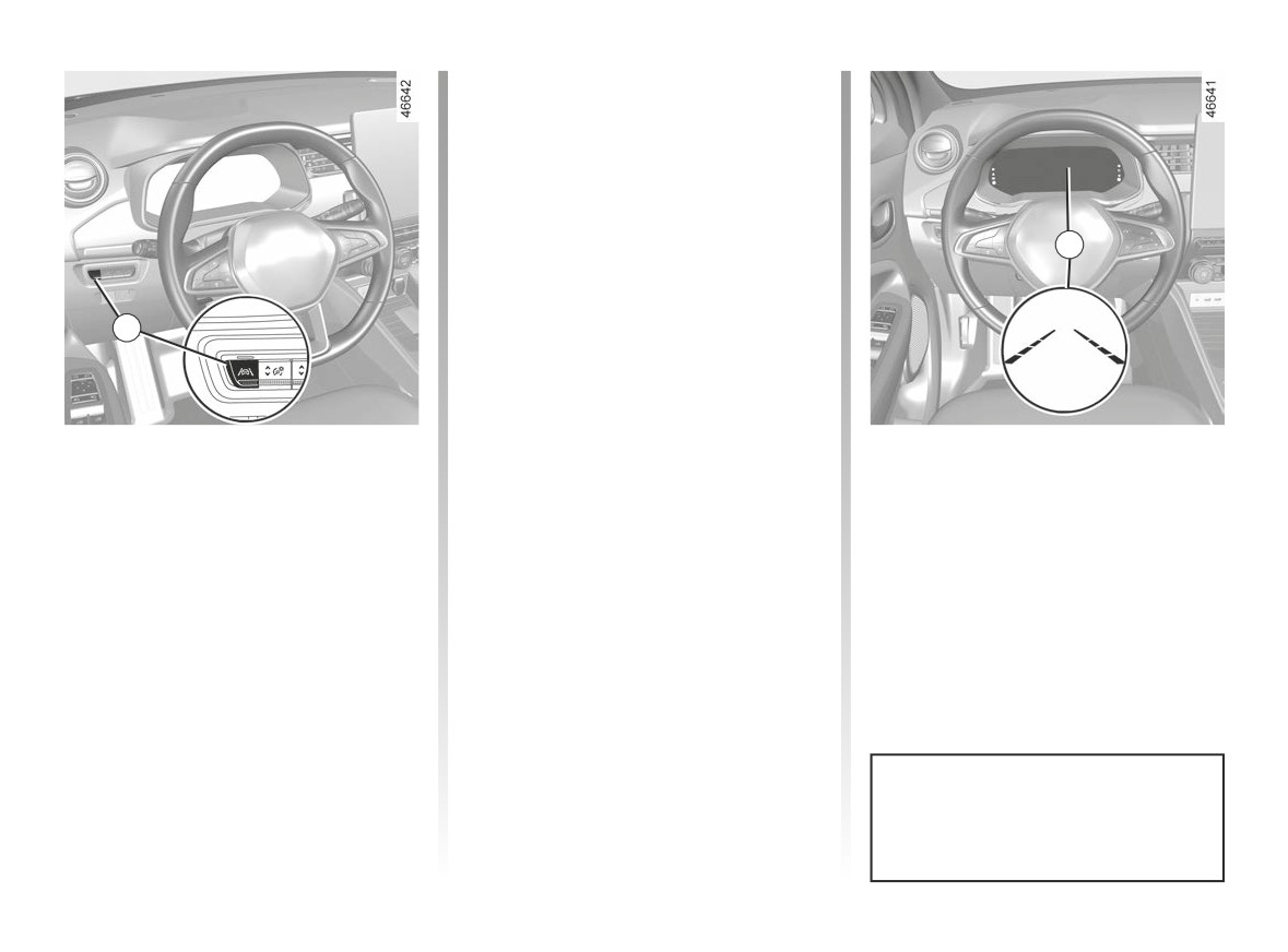
When the function is activated, the
warning light and the left and
right lines 3 are displayed in grey on the
instrument panel.
The function is set to notify the
driver if:
3
- speed is between approximately
43 mph (70 km/h) and 112 mph
(180 km/h);
2
and
- the
warning light and left/right
line indicators 3 are coloured white.
Activation/deactivation
The warning function is triggered
The function alerts the driver:
if the vehicle breaches a line or ap-
To activate the function, press the 2
- by a vibration in the steering wheel;
proaches a roadside (divider, barrier,
switch as many times as required to
and
pavement, embankment, etc.) without
select “Lane Departure Warning” on
the direction indicator lights being ac-
the instrument panel. The “Lane depar-
- the
warning light and 3 the in-
tivated.
dicator for the crossed line turn red.
ture warning on” message and “”
warning light are displayed on the in-
strument panel.
To disable the function, press the 2
switch as many times as required to
select
“Lane departure warning off”
(or, depending on the vehicle “Lane
Keeping deactivated”) on the instru-
ment panel. Warning light
goes
Each time the vehicle is started,
out on the instrument panel.
the function continues the mode
saved the last time the engine was
stopped.
2.36
CarManuals2.co
LANE DEPARTURE WARNING (3/4)
Temporarily not available
Adjustment
- very fast lane departure;
With the vehicle stationary, engine run-
- driving continuously on a line;
ning, from the multimedia screen 4
- four seconds approximately after
select the “Settings” menu, “Vehicle”
4
changing lanes;
tab, the
“Driving assistance” menu,
- tight bends;
then “Lane”:
- impaired visibility;
- “Vibration”: adjust the steering wheel
- activation of one of the direction indi-
vibration level;
cator lights;
- hard acceleration etc.
- “Alert”: adjust the sensitivity level for
line detection. To do this, select:
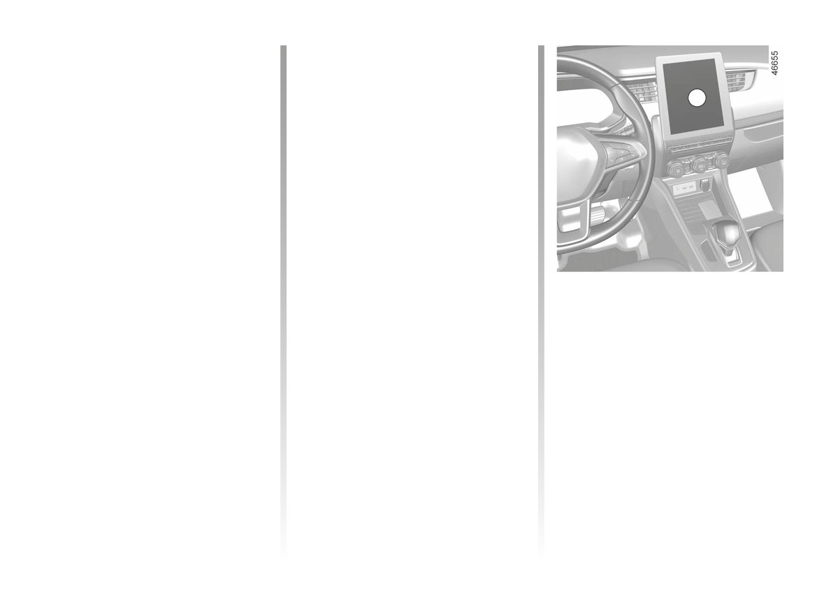
When the function is not available, the
- “Late”: line detected when cross-
ing;
warning light and the left/right in-
- “Standard”: line detected on ap-
dicators turn to grey on the instrument
proach;
panel.
- “Early”: line detected nearby.
Operating faults
Please refer to the multimedia instruc-
Conditions for non-activation
tions for further information.
In the event of a malfunction, the left
of the system
and right line indicators (and, depend-
The system cannot be activated when:
ing on display style, the
warning
- reverse gear is engaged;
light) disappear or stay grey on the in-
- the field of vision of the camera is ob-
strument panel.
structed;
In some cases, they are accompanied
- the® warning light is displayed.
by the “Front camera to check” mes-
The
warning light and the left/
right line indicators turn to grey on the
instrument panel.
instrument panel.
Consult an approved dealer.
2.37
CarManuals2.co