Renault Kangoo E-Tech (2023 year). Manual in english - page 8

REAR SEATS: functions (3/3)
When moving the rear
seats:
When refitting the seat-
back, make sure it is cor-
- check that no one is near
rectly locked in place.
to any of the moving parts;
If seat covers are fitted,
- check that there is sufficient
make sure these do not prevent the
space around the seat.
seatback latch from locking in.
Make sure that the seat belts are
For safety reasons, carry out any
positioned correctly.
adjustments when the vehicle is sta-
Reposition the headrests.
tionary.
3.37
CarManuals2.co
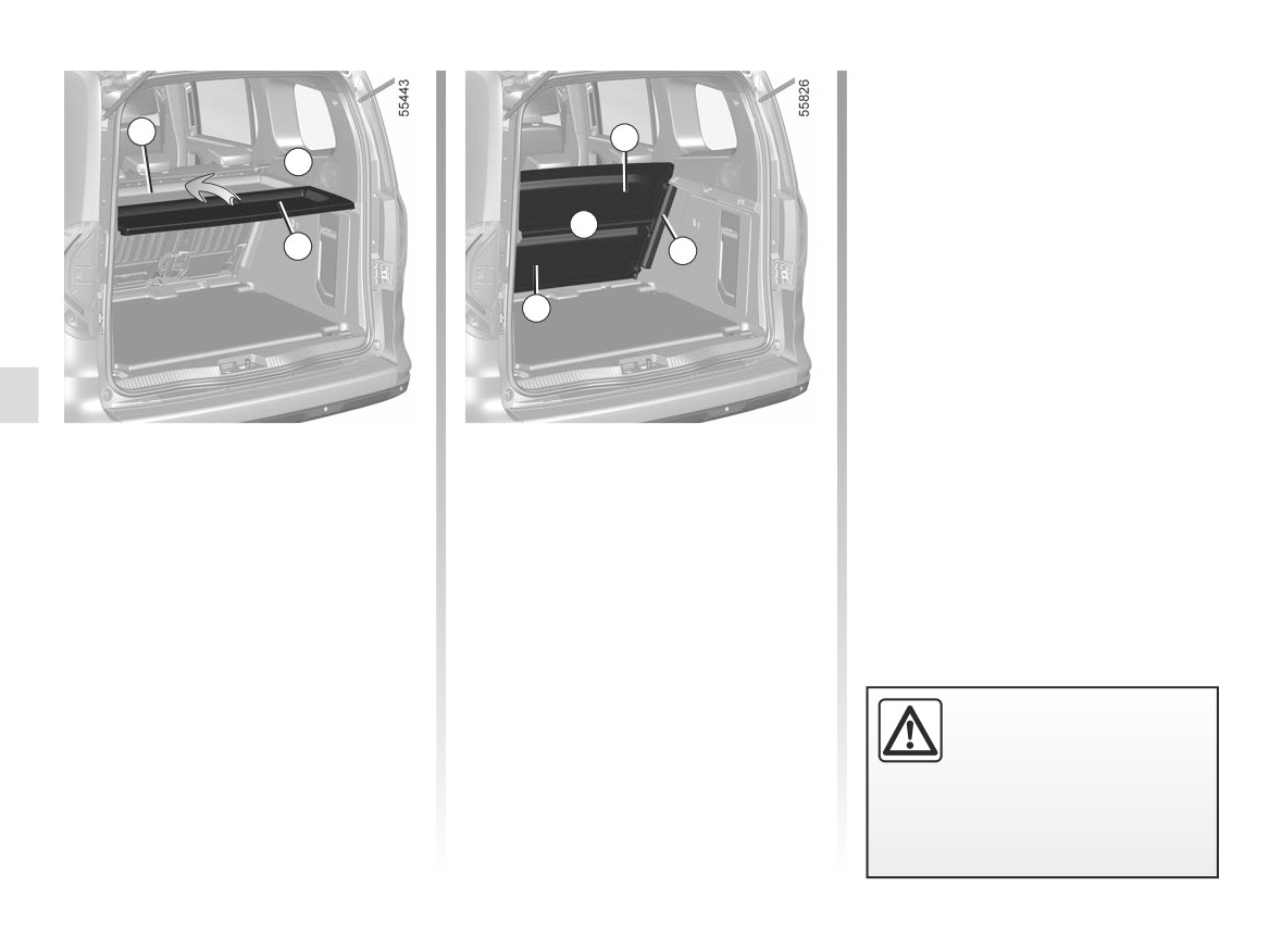
REAR PARCEL SHELF
1
2
A
B
2
3
1
The shelf is made up of two rigid sec-
- Storage position B.
tions.
To store the parcel shelf, slide it into the
There are two possible positions:
runner 3 behind the rear bench seat-
back.
- top position A;
In this case, you can fold section 2 onto
section 1 by lifting it as shown by the
arrow.
Do not place any heavy or
hard object on the parcel
shelf. These may pose a
risk to the vehicle occu-
pants if the driver has to brake sud-
denly or if the vehicle is involved in
an accident.
3.38
CarManuals2.co
LUGGAGE NET (1/2)
4
1
3
A
A
3
7
2
5
5
6
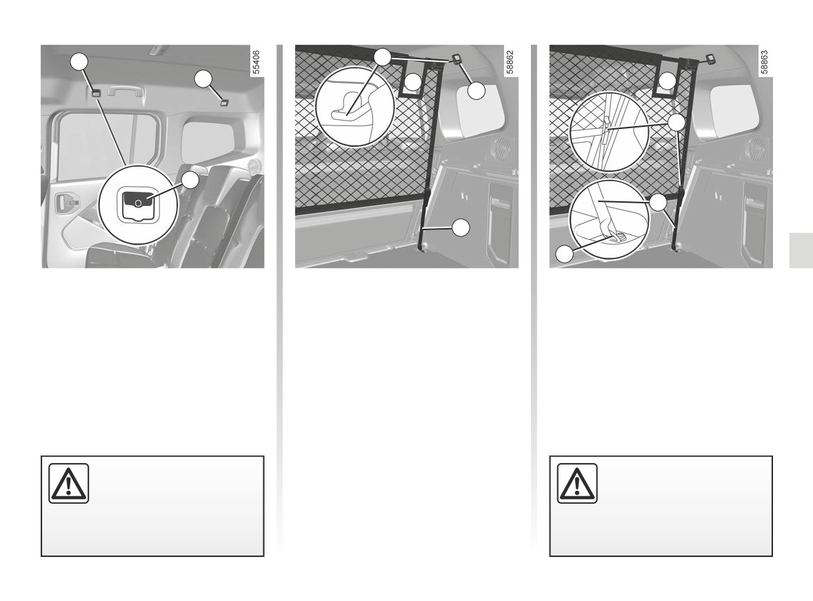
On equipped vehicles, the luggage net
Fitting the luggage net
can be used, when transporting ani-
behind the rear seats
mals or luggage, to separate them from
the passenger section.
Inside the vehicle and on each side:
It is fitted behind the rear bench seat
- insert the top rod of the net 4 into the
or behind the driver and front passen-
anchorage points 3 (the opening of
ger seats.
the net A must be positioned on the
right-hand side of the vehicle);
- pass the lower straps 5 of the net
through the anchorage points 6;
- then insert them into the 7 net lock-
ing system;
The luggage net is de-
- adjust the net strap 5 so that it is taut.
The luggage net must not
signed to retain a maximum
be used to hold objects.
weight of 10 kg.
Risk of injury.
Risk of injury.
3.39
CarManuals2.co
LUGGAGE NET (2/2)
1
1
4
9
8
2
5
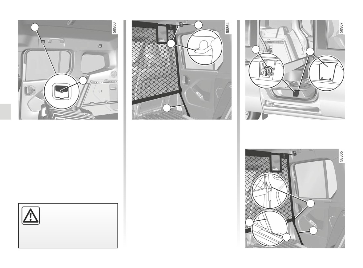
Fitting the luggage net
-
insert the upper rod of the net 4 into
the anchoring points 1;
behind the front seats
-
remove the covers 8 to access the
Inside the vehicle and on each side:
anchorage points 9;
- place the entire bench seat in the
-
pass the lower straps 5 of the net
flat-floor position ➥ 3.35;
through the anchorage points 9;
- lift the covers 2 to access the an-
-
then insert them into the 7 net lock-
chorage points 1;
ing system;
-
adjust the strap 5 of the net so that
it is taut (adjust the right-hand strap
first).
7
Do not install the luggage
net in this position when a
passenger is occupying a
5
rear seat.
5
9
3.40
CarManuals2.co
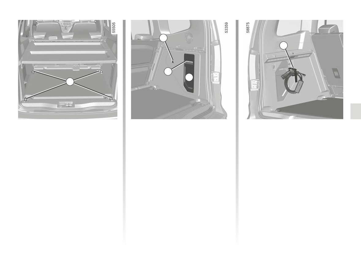
LUGGAGE COMPARTMENT STORAGE SPACE AND FITTINGS
2
4
3
A
1
Anchorage points
Bag hooks 2
Charging cable storage strap
Attachment points 1.
Maximum weight per hook: 5 kg.
Use the strap 4 to attach and store the
cable once you have wound it up.
Storage compartment A
Unclip the access flap 3.
3.41
CarManuals2.co
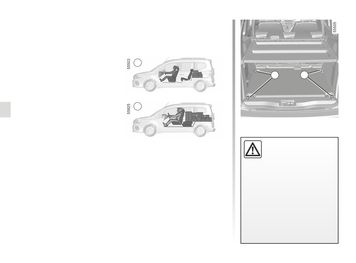
TRANSPORTING OBJECTS IN THE LUGGAGE COMPARTMENT (1/4)
Always position the objects transported
so that the largest surface is against:
- the rear bench seatback, for normal
loading (example A);
A
1
1
– the front seatbacks with the rear seat-
B
backs folded down, as is the case for
maximum loads (example B).
Always position the heavi-
est items directly on the
floor. Use the lashing
points 1 on the boot floor, if
Ensure that the objects being trans-
these are fitted to the vehicle. The
ported are evenly distributed throughout
luggage should be loaded in such a
the loading area.
way that no items will be thrown for-
ward and strike the occupants if the
If you have to place objects on the folded
driver has to brake suddenly. Fasten
seatback, it is necessary that you lower
the rear seat belts, even if the seats
the headrests before folding the seat-
are not occupied.
back so that it can be folded as flat as
possible against the seat.
3.42
CarManuals2.co
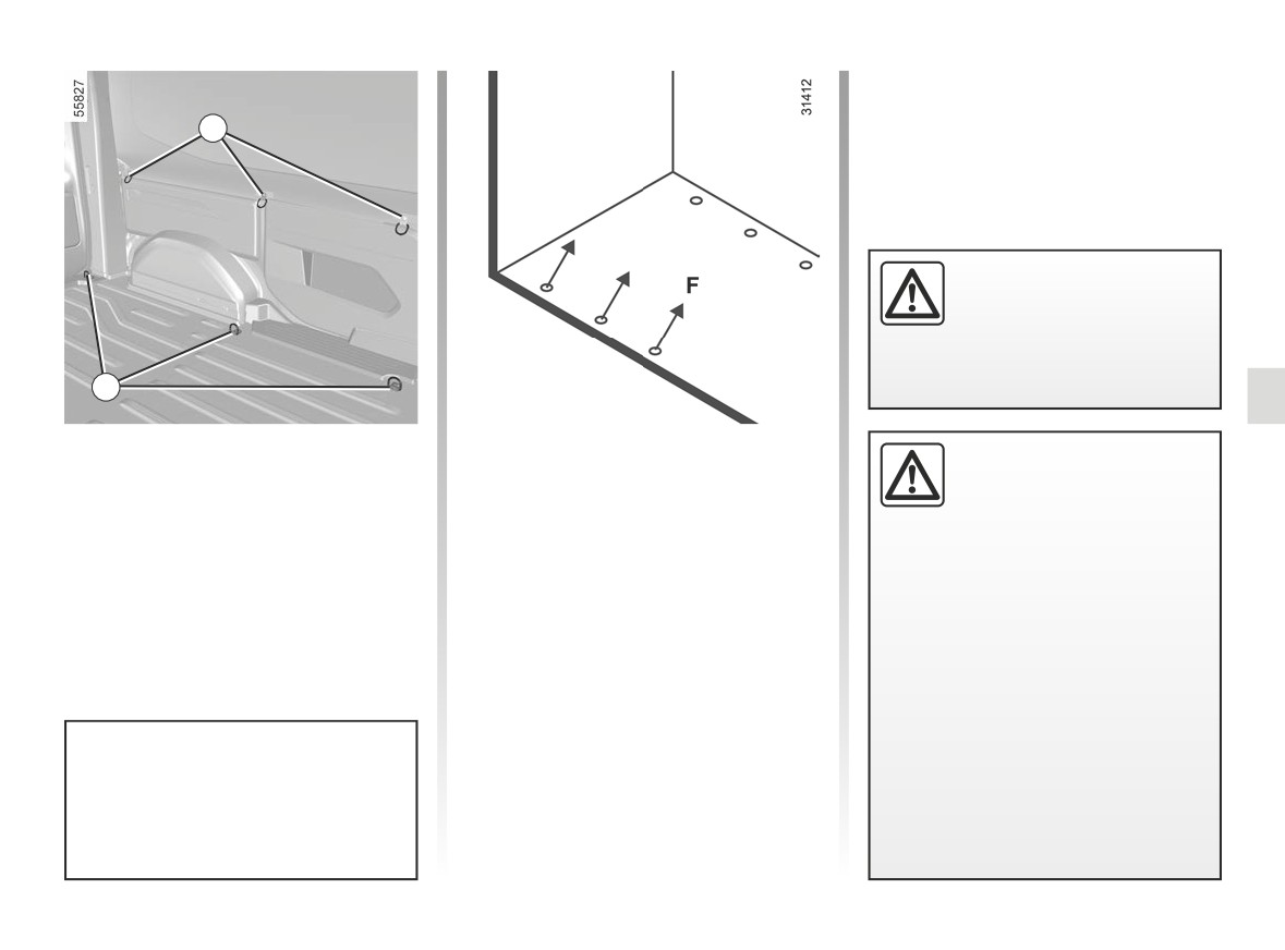
TRANSPORTING OBJECTS IN THE LUGGAGE COMPARTMENT (2/4)
2
For your safety, check that
all the vehicle’s doors are
properly closed before
starting the engine.
3
Transporting objects in the
Special note for van version
While driving with the right
rear load area
rear hinged door open,
Rotary rings 3:
always secure transported
Depending on the vehicle, rotating
F max: 400 daN
loads. The left-hand door,
rings 2 and 3 can be used to prevent
which remains shut, should not be
transported objects from moving. The
used to hold transported loads in
number of rings and their locations may
place. Using the right rear hinged
vary depending on the vehicle.
door open while driving should only
be done in exceptional cases.
In any event, please refer to local
legislation.
Risk of loads falling on the road
surface.
The sole purpose of these rings 2 is
to prevent transported objects from
moving. The objects must be se-
cured to the mounting rings 3 on the
vehicle floor beforehand.
3.43
CarManuals2.co
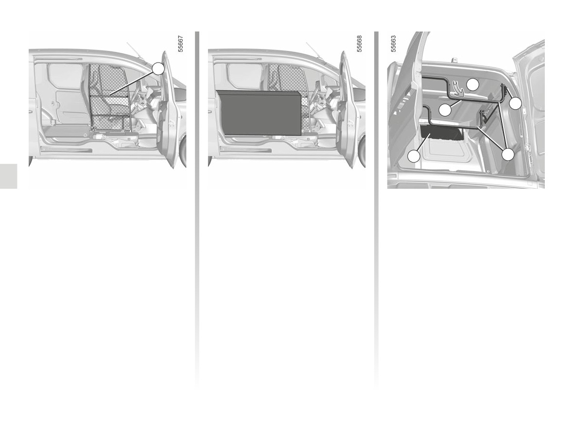
TRANSPORTING OBJECTS IN THE LUGGAGE COMPARTMENT (3/4)
4
C
6
5
8
7
“Open Sesame” version
To do this, pivot the partition 4. Please
Recess 8 and roof rack 7
observe the procedure when pivoting
(depending on the vehicle)
Depending on the width and length of
the partition ➥ 1.62.
objects carried in the rear load area,
Depending on the length of the objects
use the front passenger door and slid-
being transported in the rear load area,
ing side door openings.
you can use the recess 8 or the roof
rack 7.
Position for use
With the roof rack in the storage po-
sition, pull the lever 6 downwards to
unlock the roof rack, then hold the roof
rack bar 5 and pull it towards you until it
locks (movement C).
The roof rack locks automatically.
Check that the bonnet is correctly
locked.
3.44
CarManuals2.co
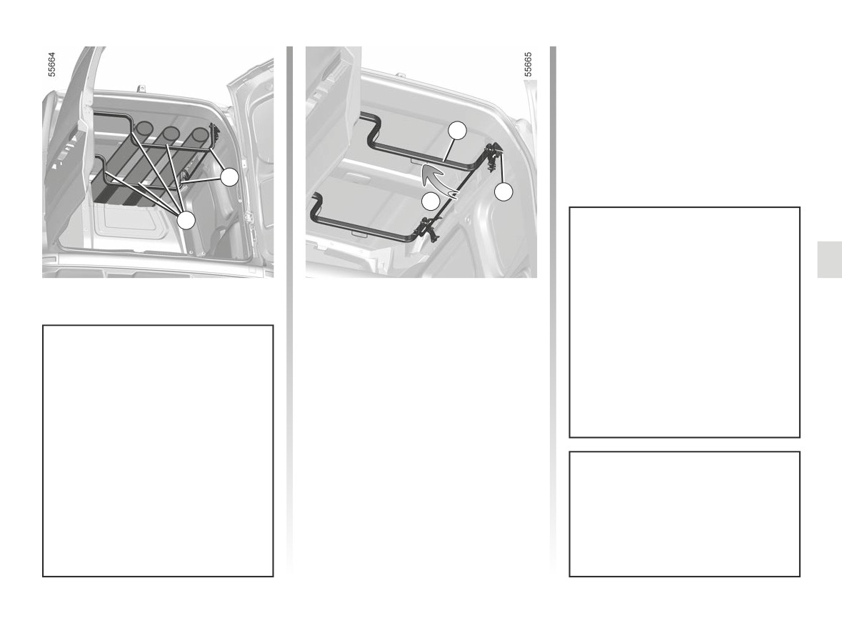
TRANSPORTING OBJECTS IN THE LUGGAGE COMPARTMENT (4/4)
5
7
6
D
9
Maximum permissible load weight
Storage position
on roof rack 7: 30 kg evenly distrib-
uted.
With the roof rack in the operating po-
sition, pull the handle 6 downwards to
Maximum load length:
unlock the roof rack, hold the roof rack
- standard chassis: 2 metres;
bar 5 and push it upwards until it locks
(movement D).
- long chassis: 2.5 metres.
Always secure the transported
loads using the rings 9.
The roof rack locks automatically.
Check that the bonnet is correctly
Make sure that you abide by the
locked.
maximum authorised length and
load weight.
Prepare any protections that may
be required and adapt your driving
to minimise the movement of the
When handling the roof rack, ensure
transported load and to avoid dam-
that nobody is near the moving
aging the vehicle or the load.
parts.
3.45
CarManuals2.co
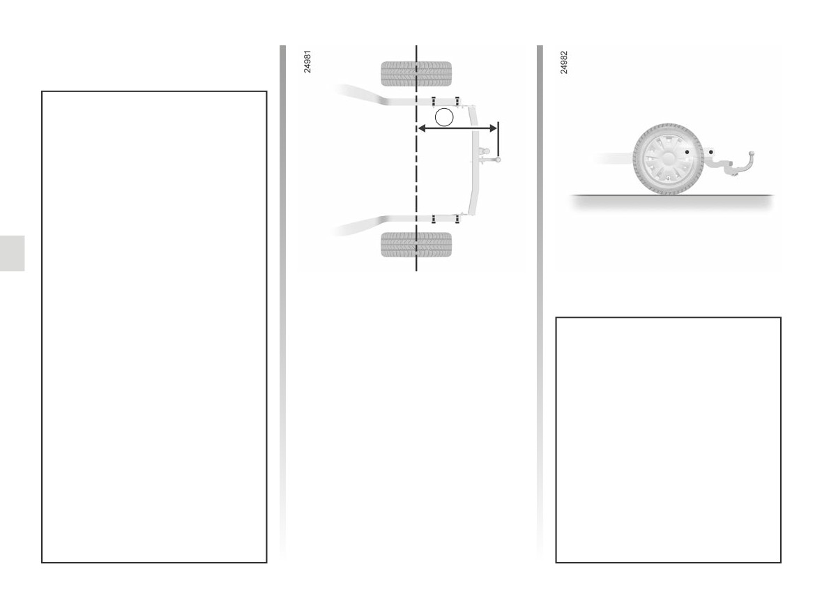
TRANSPORTING OBJECTS towbar
A
Permissible nose weight, maxi- -
mum permissible towing weight
braked and unbraked: ➥ 6.7.
Choice and fitting of towing
equipment
Maximum weight of towing equip-
ment:
- 7.2 kg on a vehicle with towing
pre-equipment;
Dimension A (maximum)
- 28.5 kg on a vehicle without
Standard chassis
towing pre-equipment.
A = 935 mm.
It is not permitted to fit a mechanical
Long chassis
towing device (ball, hook, etc.) that
A = 975 mm.
is removable without tools or retract-
Any towing device must not ob-
able if it cannot be easily removed
struct any lighting component or
or repositioned when not in use.
the number plate when not in use.
Mechanical towing devices (ball,
For fitting and conditions of use,
hook, etc.) which can be removed
refer to the equipment’s fitting in-
without tools and retractable objects
structions.
must be removed or repositioned
Please keep these instructions with
when they are not in use.
the rest of the vehicle documenta-
In all cases, you must comply with
tion.
the regulations of the particular
country you are in.
3.46
CarManuals2.co
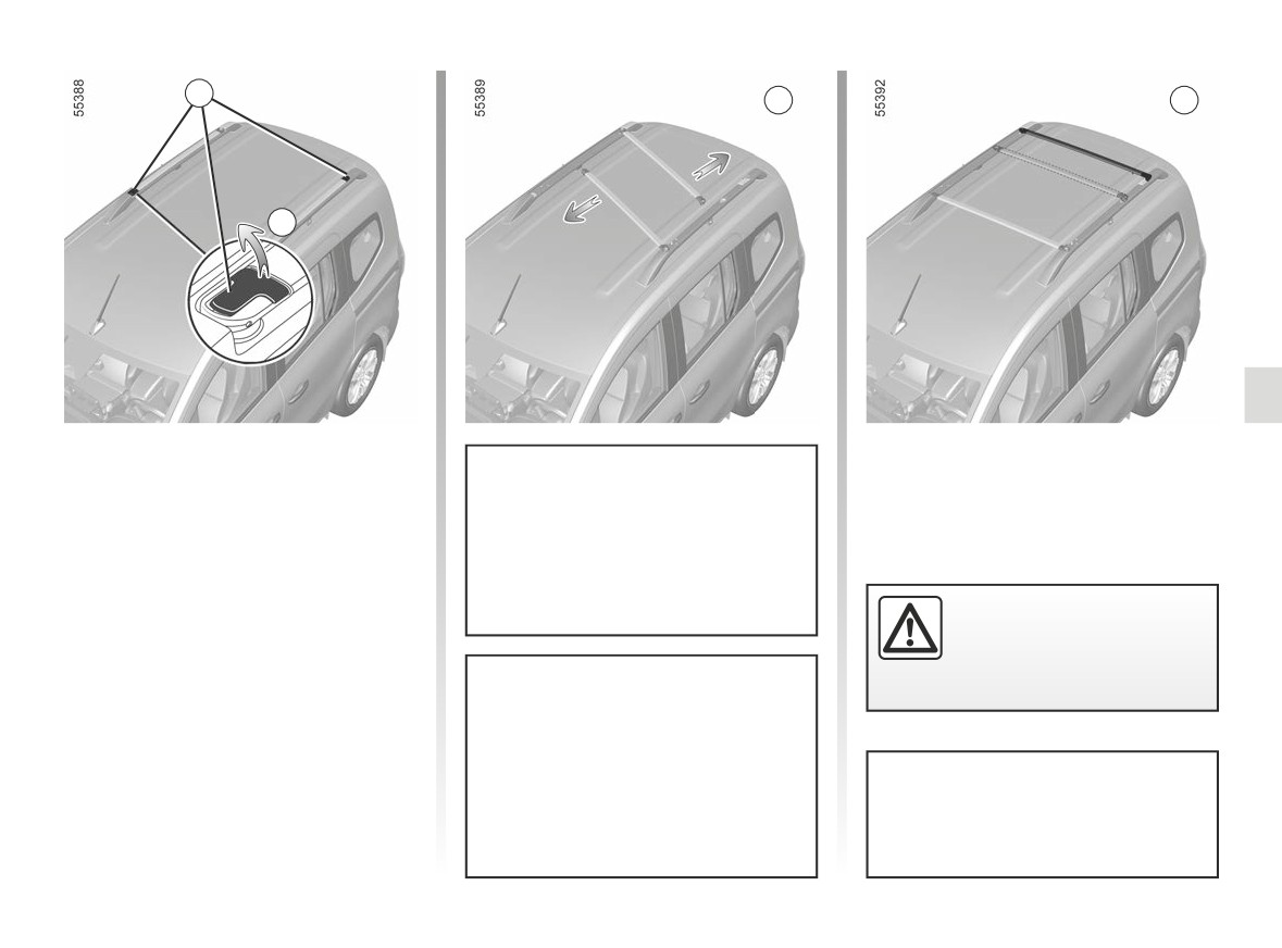
MODULAR ROOF BARS (1/2)
1
B
C
A
Before transporting a load on the mod-
ular roof bars, they must be set to their
operating position:
- Unclip the levers 1 (movement A);
When handling, ensure that the
bars do not touch the vehicle roof as
- Raise the bars sufficiently to allow
they may scratch the roof.
them to be pivoted (figure B);
- Lock the bars in the transverse
Make sure that the two roof
position by clipping the levers
1
bars are correctly posi-
(figure C);
tioned and locked.
- Check that they are correctly locked.
It is strictly forbidden to place the
modular roof bars in the transverse
position
(carrying position) when
Maximum weight on each roof bar:
entering a roller-type car wash.
40 kg evenly distributed (80 kg over
two roof bars).
3.47
CarManuals2.co
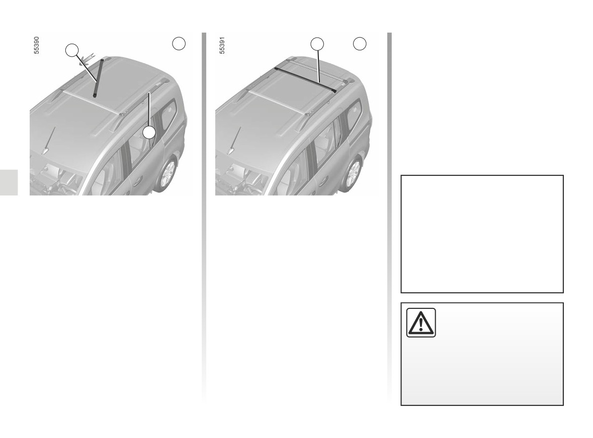
MODULAR ROOF BARS (2/2)
D
2
E
2
3
To slide the bar
Once you have chosen the position,
pivot the bar and lock it in the trans-
When not using the bars in trans-
Roof bar 2 can be slid to move it
verse position (figure E).
verse position, refit the bars in lon-
closer to or further from the other bar
gitudinal position in order to opti-
(figure D).
Check that both bars are correctly
mise fuel consumption and avoid air
locked in position.
There are two positions: centre or rear.
noise.
With the bar unlocked, pull it towards
the front or the rear of the vehicle to
slide it in rail 3.
Check that the objects and/
or accessories (bike rack,
roof box, etc.) fitted to the
roof bars are correctly po-
sitioned, evenly distributed and se-
cured.
3.48
CarManuals2.co
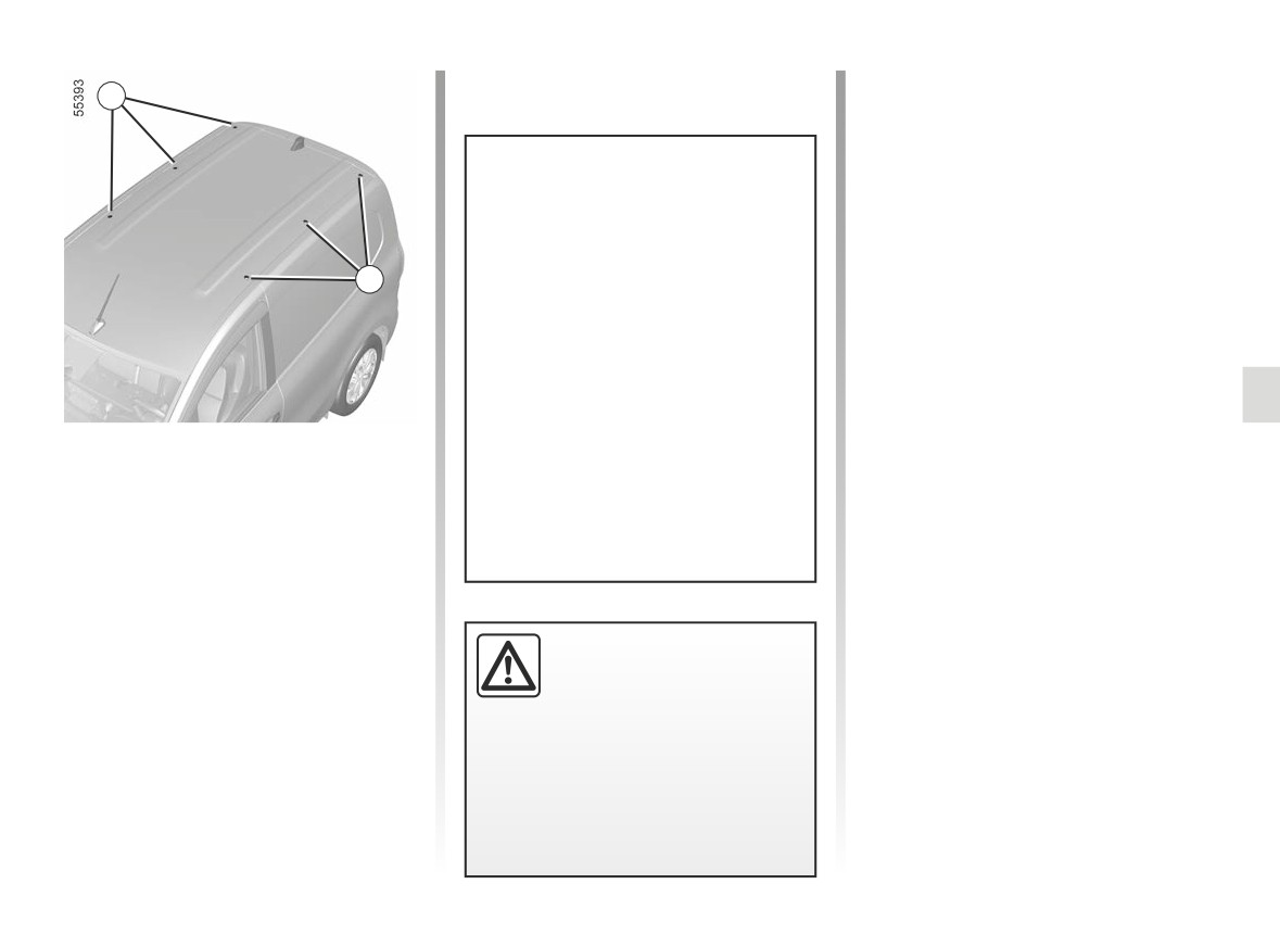
ROOF ANCHORAGE POINTS
User precautions
1
Handling the tailgate
Before operating the tailgate, check the
objects and/or accessories (bike rack,
roof box, etc.) fitted on the roof bars:
For information on the range of
these must be correctly positioned and
equipment adapted to your vehi-
secured, and must not prevent the tail-
cle, we advise you to consult an ap-
gate from operating correctly.
1
proved Dealer.
Refer to the fitting instructions for in-
formation on how to fit roof bars and
conditions of use.
Please keep these instructions with
the rest of the vehicle documenta-
tion.
Unscrew the blanking covers 1 in order
to access the mounting points.
Maximum permissible load on
roof: 100 kg (including carrying de-
vices).
If original roof bars, ap-
proved by our Technical
Department, are supplied
with screws, only use these
screws for attaching the roof bars to
the vehicle.
3.49
CarManuals2.co

3.50
CarManuals2.co

Section 4: Maintenance
Bonnet
4.2
Levels
4.4
coolant
4.4
brake fluid
4.5
windscreen washer reservoir
4.5
Secondary 12 V battery
4.6
Tyre pressure
4.8
Bodywork maintenance
4.10
Interior trim maintenance
4.13
4.1
CarManuals2.co
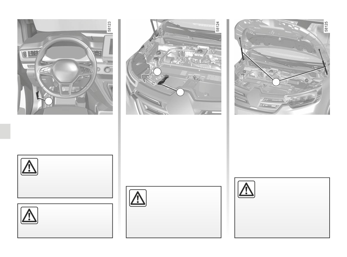
BONNET (1/2)
A
3
2
1
To open the bonnet, open a door and
Opening the bonnet
pull the 1 handle, located on the left-
To unlock, gently lift the bonnet and
hand side of the dashboard.
push tab 2 in the direction of arrow A to
release the bonnet.
Lift the bonnet, guiding it up, and it
will rest in position with the help of two
Before carrying out any
struts 3.
action in the engine com-
partment, you must switch
off the ignition.
➥ 2.2
After any procedure in the
➥ 2.3.
engine compartment, make
When working in the engine
sure that you do not forget
compartment, ensure that
anything (cloth, tools, etc.).
the windscreen wiper stalk
These may damage the engine or
Do not press down on the
is in the park position.
cause a fire.
bonnet: there is a risk that
Risk of injury.
the bonnet may accidentally
close.
4.2
CarManuals2.co

BONNET (2/2)
Closing the bonnet
Before closing the bonnet, make sure
that nothing has been left in the engine
compartment.
To close it again, hold the bonnet in the
The vehicle drive system
middle and lower it to 25 cm above the
in an electric vehicle uses
closed position, then release it. Ensure
a direct voltage of approxi-
that the bonnet is properly closed.
mately “400 V”.
If it does not lock itself under its own
This system can get hot during
weight, gently push it until it fully locks.
and after switching off the ignition.
Respect warning messages given
on the labels in the vehicle.
Any intervention or modification
on the vehicle’s “400 V” electrical
system (components, cables, con-
nectors, traction battery) is strictly
prohibited.
Risk of serious injury and/or elec-
Ensure that the bonnet is
tric shock which may endanger
properly locked.
life.
Check that nothing is pre-
venting the catch from lock-
The engine cooling fan may also
ing (gravel, cloth, etc.).
start at any moment. The
label in the engine compartment re-
minds you of this.
In the event of even a slight
Risk of injury.
impact involving the radi-
ator grille or bonnet, have
the bonnet lock checked by
an approved dealer as soon as pos-
sible.
4.3
CarManuals2.co
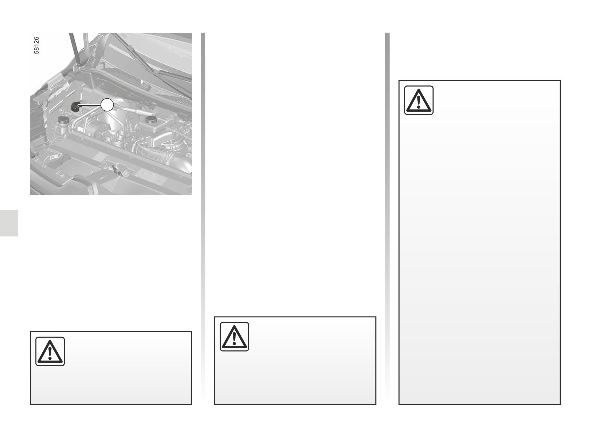
LEVELS (1/2)
Checking intervals
Replacement intervals
Check the coolant level regularly
Refer to the Maintenance Document for
(very severe damage is likely to be
your vehicle.
caused to the engine if it runs out of
coolant).
The vehicle drive system
If the level needs to be topped up, only
in an electric vehicle uses
1
use products approved by our Technical
a direct voltage of approxi-
Department which ensure:
mately “400 V”.
- protection against freezing;
This system can get hot during
- anticorrosion protection of the cool-
and after switching off the ignition.
ing system.
Respect warning messages given
on the labels in the vehicle.
Note: for a new vehicle in the running-in
phase: the coolant level may be higher
Any intervention or modification
than the “MAXI” mark on the tank, then
on the vehicle’s “400 V” electrical
drop to between the “MINI” and “MAXI”
system (components, cables, con-
marks. This does not present a risk.
nectors, traction battery) is strictly
Coolant
prohibited.
The level is checked with the engine
switched off and on flat ground. The
Risk of serious injury and/or elec-
level when cold must be between the
tric shock which may endanger
“MINI” and “MAXI” marks on the cool-
life.
ant reservoir 1.
The engine cooling fan may also
Top this level up when cold before the
“MINI” mark is reached.
start at any moment. The
label in the engine compartment re-
minds you of this.
No operations should be
Risk of injury.
carried out on the cooling
Do not do any work under
circuit when the engine is
the bonnet when the vehicle
hot.
is charging or when the igni-
tion is switched on.
Risk of burns.
4.4
CarManuals2.co
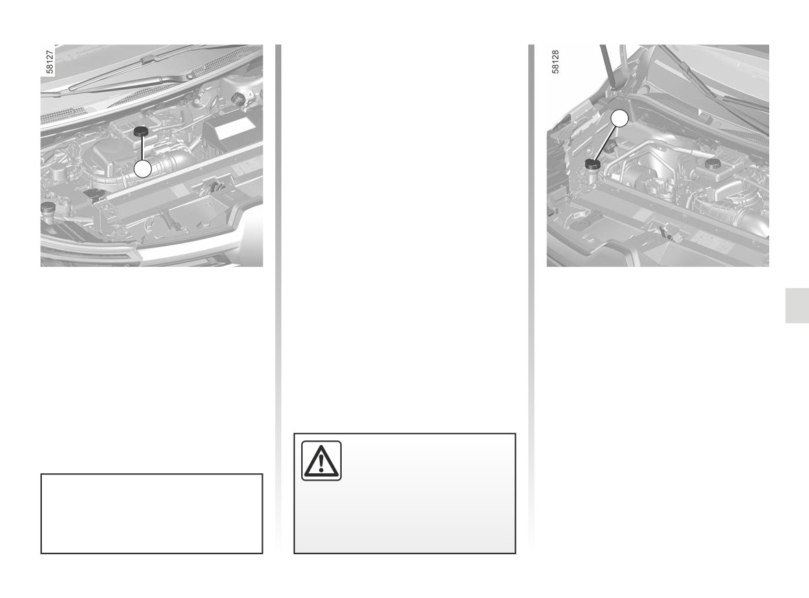
LEVELS (2/2)
Topping up
After any operation on the hydraulic
circuit, a specialist must replace the
fluid. Only use fluids approved by our
Technical Department (and taken from
3
a sealed container).
Level 2
2
It is normal for the level to drop as
the linings become worn, but it should
never drop below the “MIN” warning
line.
If you wish to check the disc wear your-
self, you should obtain the document
explaining the checking procedure from
our network or from the manufacturer’s
website.
Brake fluid
Windscreen washer
The level should be read with the engine
reservoir
switched off and on level ground. This
Topping up
should be checked frequently, and im-
mediately if you notice even the slight-
Open cap 3, fill until you can see the
est loss in braking efficiency.
fluid, then refit the cap.
Replacement intervals
Liquid
Refer to the Maintenance Document for
Screen wash product (product with an-
your vehicle.
tifreeze in winter).
When working in the engine
compartment, ensure that
Jets
the windscreen wiper stalk
Use a tool such as a needle to adjust
is in the park position.
If there is an abnormal or repeated
the height of the windscreen washer
drop in the fluid level, please consult
Risk of injury.
jets.
an authorised dealer.
4.5
CarManuals2.co
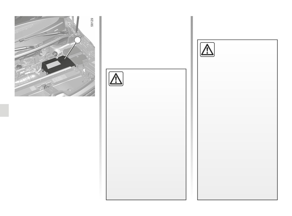
SECONDARY 12 V BATTERY (1/2)
Maintenance/replacement
The charge status of the 12 volt bat-
tery 1 can decrease, especially if you
use your vehicle:
1
- when the outside temperature drops;
- after extended use of energy-con-
The vehicle drive system
suming devices with the engine
in an electric vehicle uses
switched off.
a direct voltage of approxi-
mately “400 V”.
This system can get hot during
For your own safety and for
and after switching off the ignition.
the proper operation of the
Respect warning messages given
vehicle’s electrical equip-
on the labels in the vehicle.
ment
(lights, windscreen
Any intervention or modification
wipers, ABS, etc.), any interven-
on the vehicle’s “400 V” electrical
The secondary battery is a 12 V battery:
tion on the secondary 12 V battery
system (components, cables, con-
this supplies the energy required to op-
(removal, disconnection, etc.) must
nectors, traction battery) is strictly
erate vehicle equipment (lights, wind-
categorically be performed by a
prohibited.
screen wipers, audio system, etc) and
specialist professional.
Risk of serious injury and/or elec-
certain safety systems, such as ABS.
Risk of serious burns or electric
tric shock which may endanger
shocks.
You should not open it or add any
life.
Respect categorically the replace-
fluid.
ment intervals (without exceeding
The engine cooling fan may also
them) as stated in the maintenance
document.
start at any moment. The
The battery is a specific type.
label in the engine compartment re-
Please ensure it is replaced with the
minds you of this.
same type.
Risk of injury.
Call an approved Dealer.
4.6
CarManuals2.co
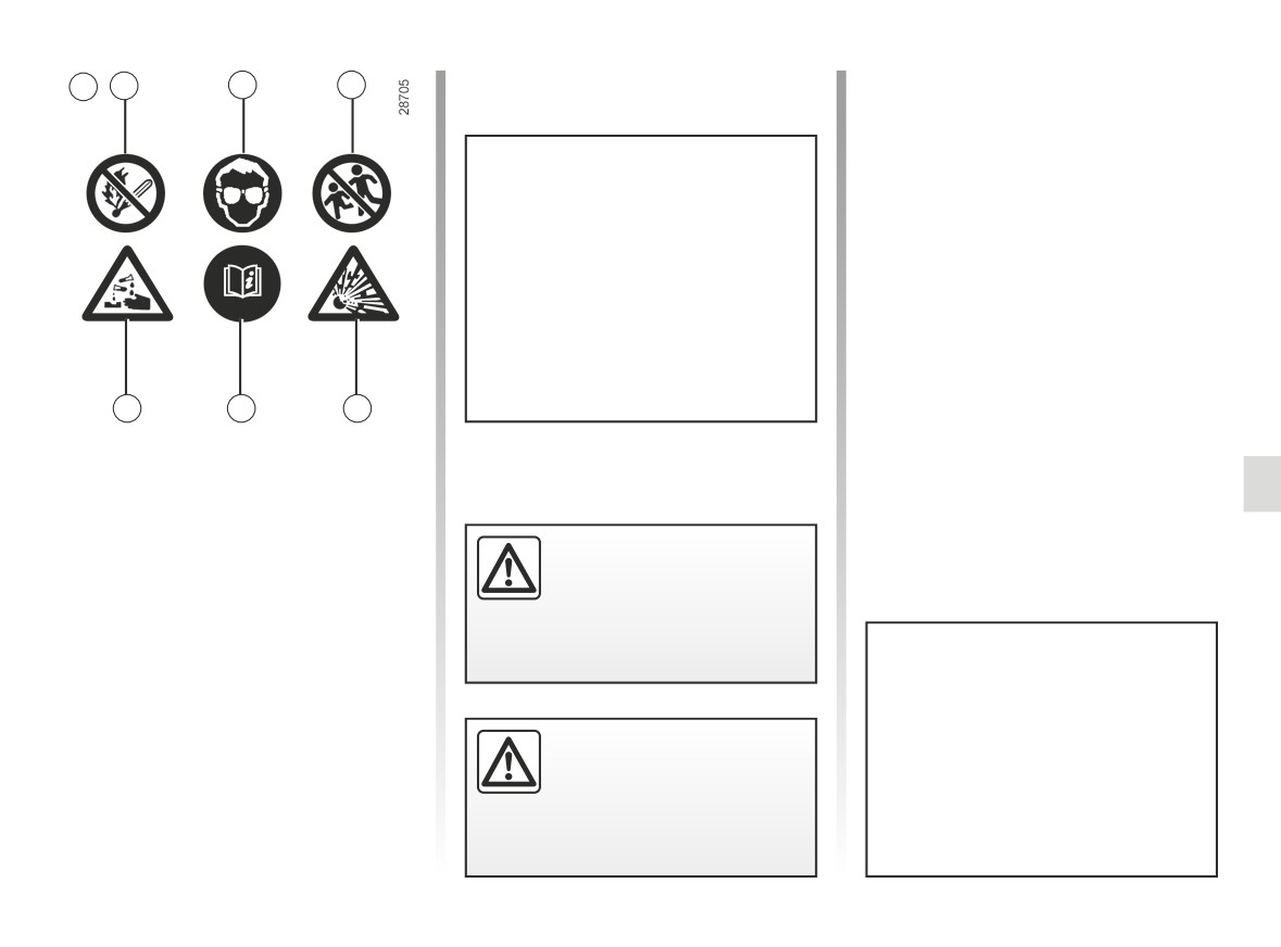
SECONDARY 12 V BATTERY (2/2)
A
2
3
4
Breakdown recovery
To avoid damaging your vehicle, do
not recharge the secondary 12 V
battery using:
- an external battery charger;
- a battery from another vehicle.
Please contact an Authorised
Dealer.
7
6
5
Label A
Observe the indications on the battery.
2 naked flames and smoking are forbid-
den;
Do not do any work under
3 eye protection required;
the bonnet when the vehicle
4 keep away from children;
is charging or when the igni-
5 explosive materials;
tion is switched on.
6 please consult the vehicle user
manual;
7 corrosive substances.
Do not use your electric vehicle to
restart the 12 volt battery in another
Do not disconnect the sec-
vehicle. The 12 volt electric power of
ondary 12 V battery.
an electric vehicle is not enough to
perform such an operation.
Risk of serious burns or
Risk of damage to vehicle
electric shocks.
4.7
CarManuals2.co
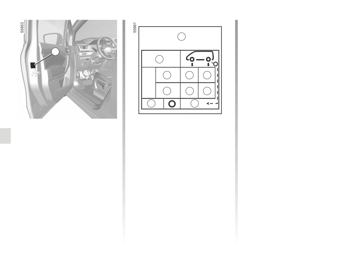
TYRE PRESSURE (1/2)
Vehicle fitted with a tyre pressure
monitoring system
A
In the event of under-inflation (punc-
tures, under-inflation etc.), the
A
warning light appears on the instrument
B
panel ➥ 2.25.
C
D
E
C
D
E
G
F
Label A
B: dimension of the tyres fitted to the
vehicle.
Open the driver’s door to read it.
C: intended driving speed.
Tyre pressures should be checked
when the tyres are cold.
D: front tyre pressure.
If the tyre pressures cannot be checked
E: rear tyre pressure.
when the tyres are cold, increase the
F: tyre pressure for the emergency
pressures from 0.2 to 0.3 bar (or 3 PSI).
spare wheel.
Never deflate a hot tyre.
G: emergency spare wheel dimensions.
4.8
CarManuals2.co

TYRE PRESSURE (2/2)
Tyre safety and chain fitting: for infor-
Vehicles used fully laden
mation on servicing conditions and, de-
(Maximum Permissible
pending on the vehicle version, the use
All-up Weight) and towing
of chains. ➥ 5.13.
a trailer
The maximum speed must be lim-
For your safety, please re-
ited to 62 mph (100 km/h) and the
spect the speed limit.
tyre pressure increased by 0.2 bar
When they need to be re-
(3 psi) ➥ 6.7.
placed, only tyres of the
Risk of tyre blowouts.
same make, size, type and profile
should be used on a single axle.
They must: either have a load ca-
pacity and speed rating at least
equal to those of the original
tyres, or conform to those recom-
mended by an authorised dealer.
Failure to heed these instructions
could endanger your safety and
affect your vehicle’s roadworthi-
ness.
Risk of loss of control of the ve-
hicle.
4.9
CarManuals2.co

BODYWORK MAINTENANCE (1/3)
A well-maintained vehicle will last
You should
Observe the vehicle stopping distances
longer. It is therefore recommended to
when driving on gravelled surfaces to
Wash your car frequently, with the
maintain the exterior of the vehicle reg-
prevent paint damage.
engine off, with cleaning prod-
ularly.
ucts recommended by our Technical
Repair, or have repaired quickly, areas
Your vehicle has been treated with very
Department (never use abrasive prod-
where the paint has been damaged, to
effective anti-corrosion products. It is
ucts). Rinse thoroughly beforehand
prevent corrosion spreading.
nevertheless subject to various outside
with a jet:
Remember to visit the body shop pe-
influences.
-
spots of tree resin and industrial
riodically in order to maintain your an-
grime;
ti-corrosion warranty. Refer to the
Corrosive agents in the
–
mud in the wheel arches and under-
Maintenance Document.
atmosphere:
neath the body which forms damp
- atmospheric pollution (built-up and
Respect local regulations about wash-
patches;
industrial areas);
ing vehicles (e.g. do not wash your ve-
-
bird droppings, which cause a
– saline atmospheres (near the sea,
hicle on a public highway).
chemical reaction with the paint that
particularly in hot weather);
rapidly discolours paintwork and
If it is necessary to clean mechani-
- seasonal and damp weather condi-
may even cause the paint to peel
cal components, hinges, etc., spray
tions (e.g. road salt in winter, water
off;
them with products approved by our
from road cleaners, etc.).
wash the vehicle immediately to
Technical Department to protect them
remove these marks since it is im-
after they have been cleaned.
Minor impacts
possible to remove them by polish-
ing;
Abrasive action
-
salt, particularly in the wheel arches
Dust and sand in the air, mud, road grit
and underneath the body after driv-
thrown up by other vehicles, etc.
ing in areas where the roads have
You should take a number of minor pre-
been gritted.
cautions in order to safeguard your ve-
Withdraw the vegetable falls (resin, film
hicle against such risks.
etc.) from the vehicle regularly.
We have selected special products
to care for your vehicle and you can
obtain these from the manufactur-
er’s accessory outlets.
4.10
CarManuals2.co

BODYWORK MAINTENANCE (2/3)
What you should not do
Wash the vehicle in bright sunlight or
freezing temperatures.
Degrease or clean using
high-pressure cleaning
Do not scrape off mud or dirt without
equipment or by spray-
pre-wetting.
ing on products not ap-
Allow dirt to accumulate on the exterior.
proved by our Technical
Department:
Allow rust to form following minor im-
-
mechanical components
(e.g.:
pacts.
engine compartment);
Do not use solvents not approved by
-
the wheels
(e.g. braking system
our Technical Department to remove
components such as brake calli-
stains as this could damage the paint-
pers);
work.
-
the underbody;
Do not drive in snow or muddy condi-
tions without washing the vehicle, par-
-
the parts with hinges (e.g. inside the
ticularly under the wheel arches and
doors);
body.
-
the painted plastic external fittings
(e.g. bumpers).
Washing the vehicle
Doing this could give rise to corrosion
Never wash the engine
or operational faults.
compartment, the charging
connection or the traction
battery with a high-pressure jet.
This risks damaging the electric
circuit.
Never wash the vehicle while it is
charging.
Risk of electric shock and a risk
to life.
4.11
CarManuals2.co

BODYWORK MAINTENANCE (3/3)
Vehicles with a matte paint
Using a roller type car wash
Cleaning stickers, decorative
finish
Return the wiper stalk to the park posi-
films, etc.
This type of paint requires certain pre-
tion ➥ 1.161, ➥ 1.165. Check the mount-
You should do the following
cautions.
ing of external accessories, additional
lights and rear view mirrors, and ensure
Use a soft cloth or cotton wool.
You should do the following
that the wiper blades are secured with
Moisten it with soapy water, then
adhesive tape.
always wipe clean with a soft cloth or
Wash the vehicle by hand using plenty
cotton wool.
of water, using a soft cloth or a gentle
Remove the radio aerial mast if your
Finally, carefully dry off with a soft dry
sponge.
vehicle is fitted with this equipment.
cloth.
Remember to remove the tape and refit
Do not do the following
the antenna after washing.
Do not do the following
Use wax-based products (polishing).
Use alcohol-based cleaning products.
Rub too hard.
Cleaning the headlights,
Use utensils (e.g. scraper).
Wash the vehicle in a roller-type car
Rub too hard.
wash.
sensors and cameras
Attach stickers to the paintwork (risk of
Use a soft cloth or cotton wool. If this
leaving marks).
does not clean them properly, moisten
Wash the area using a
the cloth with soapy water, then wipe
high-pressure clean-
clean using a soft damp cloth or cotton
ing device.
Wash the vehicle
wool.
using a high-pressure
Finally, dry off carefully with a soft dry
cleaning device.
cloth.
Do not use cleaning products con-
taining alcohol or utensils (e.g.: a
scraper).
4.12
CarManuals2.co

INTERIOR TRIM MAINTENANCE (1/2)
A well-maintained vehicle will last
Glass instrument panel
Textiles (seats, door trim, etc)
longer. It is therefore recommended to
(e.g. instrument panel, clock, exterior
Vacuum-clean the textiles regularly.
maintain the interior of the vehicle regu-
temperature display, radio display, etc.)
larly.
Use a soft cloth (or cotton wool).
Liquid stain
A stain should always be dealt with
If this does not clean them properly,
Use soapy water.
swiftly.
use a soft cloth (or cotton wool) slightly
Dab lightly (never rub) with a soft cloth,
moistened with soapy water and then
Whatever type of stain is on the trim,
rinse and remove the excess.
wipe clean with another soft damp cloth
use cold (or warm) soapy water with
or cotton wool.
natural soap.
Solid or pasty stain
Finally, carefully dry off with a soft dry
Detergents (washing-up liquid, pow-
cloth.
Carefully remove the excess solid or
dered products, alcohol-based prod-
pasty material immediately with a
ucts) should not be used.
Do not use products containing alco-
spatula (working from the edges to the
hol and/or spray fluids on the area.
Use a soft cloth.
centre to avoid spreading the stain).
Clean as for a liquid stain.
Rinse and soak up the excess.
Seat belts
Special instructions for sweets or
These must be kept clean.
chewing gum
Multimedia screen
Use products selected by our Technical
Maintenance of the screen may depend
Department
(approved outlets) or
Put an ice cube on the stain to solidify
on the type of multimedia equipment.
warm, soapy water and a sponge and
it, then proceed as for a solid stain.
Please refer to the multimedia instruc-
wipe with a dry cloth.
tions for further information.
Detergents or dyes must not be used
under any circumstances.
For further recommendations for
maintaining the interior, and/or for
any unsatisfactory results, please
see an authorised dealer.
4.13
CarManuals2.co

INTERIOR TRIM MAINTENANCE (2/2)
Removal/replacing removable
You should not:
equipment originally fitted in
Position objects such as deodorants,
the vehicle
scents etc. near air vents as this could
damage your dashboard trim.
If you need to remove equipment in
order to clean the passenger com-
partment (for example, mats), always
ensure that they are correctly refitted
and are the right way around (the driv-
er’s mat should be fitted on the driver’s
Use high-pressure
side etc.) and fit them with the compo-
cleaning equipment or
nents supplied with the equipment (for
sprays inside the pas-
example, the driver mat should always
senger compartment:
be fixed using the pre-fitted mounting
without careful use, this equipment
components).
could impair the correct functioning
With the vehicle stationary, always
of the electrical or electronic compo-
ensure that nothing will impede driving
nents in the vehicle, or have other
(anything obstructing the pedals, heel
detrimental effects.
wedged by the mat etc.).
4.14
CarManuals2.co

Section 5: Practical advice
Puncture, emergency spare wheel
5.2
Tyre inflation kit
5.4
Tools
5.8
Wheel trims - wheel
5.10
Changing a wheel
5.11
Tyres (tyre and wheel safety, use in winter)
5.13
Headlights (changing bulbs)
5.16
Rear lights and side lights (replacing bulbs)
5.18
Interior lighting (changing bulbs)
5.22
Remote control key: battery
5.28
“Hands-free” card: battery
5.30
Fitting a radio
5.32
Accessories
5.33
Fuses
5.34
Wiper blades: replacement
5.37
Towing
5.39
Operating faults
5.42
5.1
CarManuals2.co
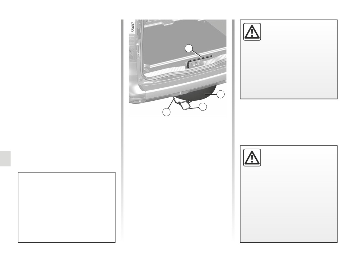
PUNCTURE, EMERGENCY SPARE WHEEL (1/2)
In case of puncture
If the vehicle is parked on
Depending on the vehicle, either an
the hard shoulder, you must
emergency spare wheel or a tyre infla-
warn other road users of
tion kit is provided ➥ 5.4.
your vehicle’s presence
1
with a warning triangle or with other
Vehicle fitted with a tyre pressure
devices as per the legislation apply-
monitoring system
ing to the country you are in.
In the event of under-inflation (punc-
tures, under-inflation etc.), the
warning light appears on the instrument
panel ➥ 2.25.
2
3
4
Emergency spare wheel 2
This is stored in cage 4 under the floor
at the rear of the vehicle.
To access the emergency spare
Do not leave the tools unse-
wheel
cured inside the vehicle as
- Open the boot lid;
they may come loose under
- loosen the nut using the wheel-
braking. After use, make
brace 1 ➥ 5.8;
sure the tools are correctly posi-
- unhook the cradle, taking it by the
tioned in their mountings: not doing
handle 3;
so presents a risk of injury.
In some cases (rear puncture, vehi-
- release the emergency spare wheel.
cle loaded with towing equipment),
The jack is designed for wheel
it is necessary to raise the vehicle
changing purposes only. Under no
(using the lifting point nearest the
circumstances should it be used for
wheel concerned) to access to the
carrying out repairs underneath the
emergency spare wheel ➥ 5.11.
vehicle or to gain access to the un-
derside of the vehicle.
5.2
CarManuals2.co
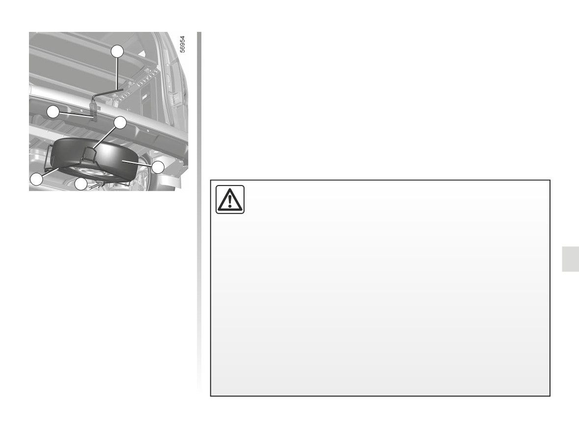
PUNCTURE, EMERGENCY SPARE WHEEL (2/2)
- attach the handle 3 by moving it
slightly to the left, if necessary, to
1
find the hook 5;
- tighten the nut using the 1 key to refit
and lock the assembly;
- check that it is correctly locked in
place.
5
3
2
4
A
If the emergency spare wheel has been stored for several years, have it
To store the wheel in the cage
checked by your Dealer to ensure that it is safe to use.
– Make sure that you reposition the
Vehicle fitted with an emergency spare wheel that differs from the
wheel 2 correctly in the cage, with
other wheels:
the valve facing downwards;
-
Never fit more than one emergency spare wheel to the same vehicle.
–
The punctured wheel is wider than the emergency spare wheel, so the height
– position the wheel as far to the right
of the vehicle ground clearance is reduced.
as possible and at the bottom of the
-
Replace the emergency spare wheel as soon as possible with a wheel identi-
cage 4 (movement A);
cal to the original one.
- ensure that the handle 3 located
-
When this is fitted to the vehicle, which must only be a temporary measure, the
on the left-hand side is raised and
driving speed must not exceed the speed indicated on the label on the wheel.
mobile;
-
Fitting an emergency spare wheel may alter the way the vehicle usually runs.
- lift the cage 4 by the handle 3 using
Avoid sudden acceleration or deceleration and reduce your speed when cor-
your left hand, while holding down
nering.
the wheel 2 at the bottom of the cage
-
If you need to use snow chains, fit the emergency spare wheel to the rear axle
using your right hand;
and check the tyre pressure.
5.3
CarManuals2.co
TYRE INFLATION KIT (1/4)
Do not attempt to use the
The kit is only approved for
B
inflation kit if the tyre has
inflating the tyres of the ve-
been damaged as a result
hicle originally equipped
of driving with a puncture.
with the kit.
You should therefore carefully check
It must never be used to inflate
A
the condition of the tyre sidewalls
the tyres of another vehicle, or any
before any operation.
other inflatable object (rubber ring,
rubber boat, etc.).
Driving with underinflated, flat or
punctured tyres can be dangerous
Avoid spillage on skin when han-
and may make the tyre impossible
dling the repair product bottle. If
to repair.
droplets do leak out, rinse them off
with plenty of water.
This repair is temporary.
Keep the repair kit away from chil-
A tyre which has been punctured
dren.
should always be inspected (and re-
paired, where possible) as soon as
Do not dispose of the empty bottle
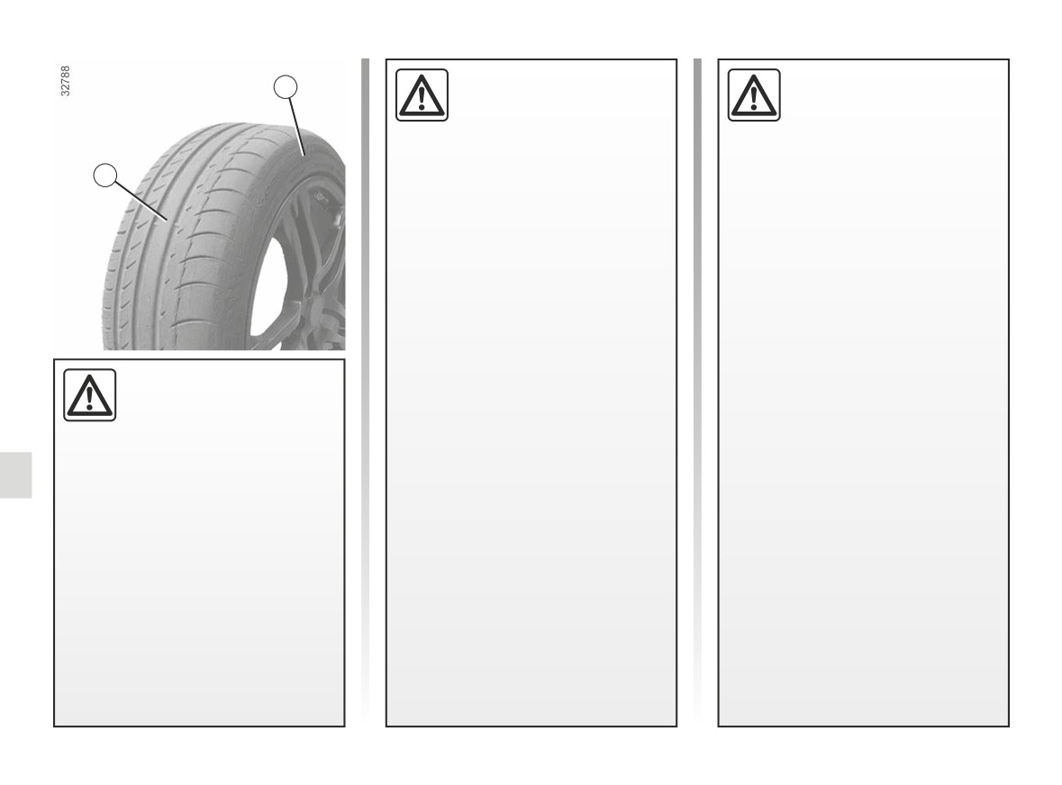
The kit repairs tyres when
possible by a specialist.
in the countryside. Return it to your
tread A has been dam-
approved dealer or to a recycling or-
aged by objects smaller
When taking a tyre which has been
ganisation.
than 4 mm. It cannot repair
repaired using this kit to be replaced,
all types of puncture, such as cuts
you must inform the specialist.
The bottle has a limited service
larger than 4 mm, or cuts in tyre
life which is indicated on its label.
When driving, vibration may be felt
sidewall B.
Check the expiry date.
due to the presence of the repair
Ensure also that the wheel rim is in
product injected into the tyre.
Contact an approved dealer to re-
good condition.
place the inflation tube and repair
product bottle.
Do not pull out the foreign body
causing the puncture if it is still in
the tyre.
5.4
CarManuals2.co
TYRE INFLATION KIT (2/4)
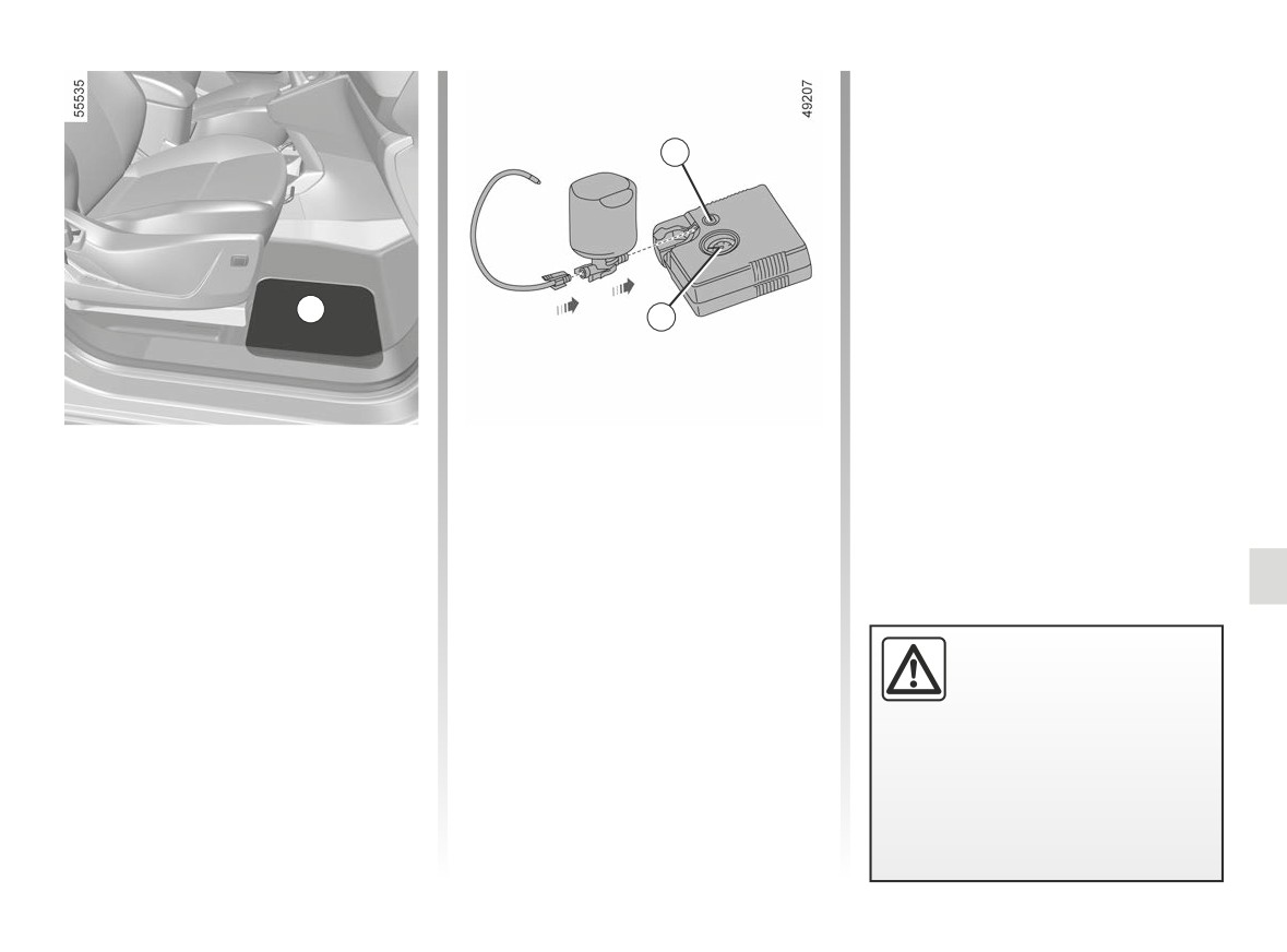
Note: while the bottle is emptying
(approximately
30 seconds), the
pressure gauge 2 will briefly indicate
a pressure of 6 bar, then the pres-
1
sure drops;
- Adjust the pressure: to increase it,
continue inflation with the kit. To
reduce it, press the button 1.
C
2
Depending on the vehicle, in the event
With the engine running and hand-
of a puncture use the kit located in the
brake applied:
storage compartment under the flap C
- Disconnect any accessories previ-
at the footwell of the front right-hand
ously connected to the vehicle’s ac-
seat.
cessories sockets;
- refer to the information on the in-
Vehicle fitted with a tyre pressure
flation kit compressor located in
monitoring system
the luggage compartment of the ve-
In the event of under-inflation (punc-
hicle and follow the instructions;
- inflate the tyre to the recommended
Before using this kit, park
tures, under-inflation etc.), the
pressure ➥ 4.8 ;
the vehicle at a sufficient
warning light appears on the instrument
- after a maximum of 15 minutes, stop
distance from traffic, switch
panel ➥ 2.25.
inflating and read the pressure (on
on the hazard warning
pressure gauge 2).
lights, apply the handbrake, ask all
passengers to leave the vehicle and
keep them away from traffic.
5.5
CarManuals2.co
TYRE PRESSURE KIT (3/4)
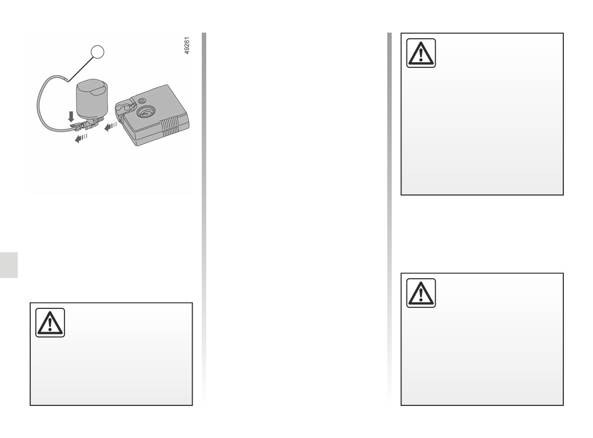
Once the tyre is correctly inflated,
Do not leave the tools unse-
remove the kit: unclip the inflation
3
cured inside the vehicle as
adapter slowly from the container 3 to
they may come loose under
prevent any product spatter and store
braking. After use, ensure
the container in plastic packaging to
that the inflation kit is correctly posi-
prevent product leaks.
tioned in its support, position it cor-
- Affix the driving recommendation
rectly in its housing, attach the strap,
label (located under the container) to
then make sure that the inflation kit
the dashboard where the driver can
access flap is properly locked.
see it.
- Put the kit away.
Risk of injury.
- At the end of this initial inflation op-
eration, air will still escape from the
tyre. You must drive a short distance
in order to seal the hole.
- Start immediately and drive at a
If a minimum pressure of 1.8 bar is
speed between 12 to 37 mph (20 to
not reached after 15 minutes, repair
60 km/h) in order to distribute the
is not possible; do not drive the ve-
product evenly in the tyre; after driv-
hicle but contact an approved dealer.
ing a distance of 2 miles (3 km), stop
and check the pressure.
- If the pressure is higher than 1.3 bar
but lower than the recommended
pressure (refer to the label affixed to
If the vehicle is parked on
the edge of the driver’s door), adjust
the hard shoulder, you must
it. Otherwise, contact an approved
warn other road users of
dealer: the tyre cannot be repaired.
Nothing should be placed
your vehicle’s presence
around the driver’s feet
with a warning triangle or with other
as such objects may slide
devices as per the legislation apply-
under the pedals during
ing to the country you are in.
sudden braking manoeuvres and
obstruct their use.
5.6
CarManuals2.co

TYRE INFLATION KIT (4/4)
Precautions when using the
kit
The kit should not be operated for more
than 15 consecutive minutes.
The container must be replaced after
the first use even if liquid remains
inside.
Following repair with the kit,
do not travel further than
120 miles (200 km). In addi-
tion, reduce your speed and
under no circumstances exceed
48 mph (80 km/h). The sticker,
which you must affix in a prominent
Please be aware that a
position on the dashboard, reminds
poorly tightened or miss-
you of this.
ing valve cap can make the
Depending on the country or local
tyres less airtight and may
legislation, a tyre repaired with the
lead to pressure loss.
inflation kit may need to be replaced.
Always use valve caps identical to
those fitted originally and tighten
them fully.
5.7
CarManuals2.co
TOOLS (1/2)
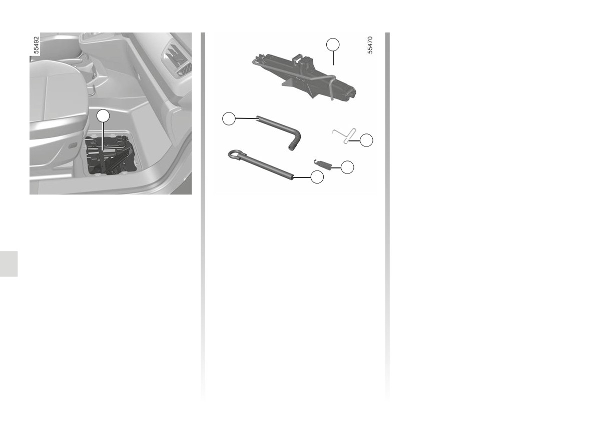
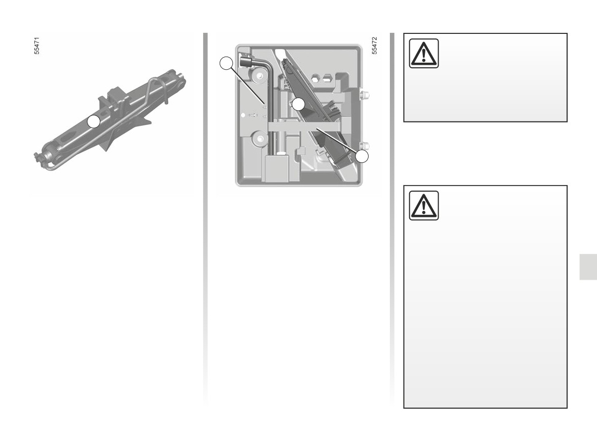
Hubcap tool 3
2
This tool is used to remove the wheel
trims.
Wheel bolt guide 4
To finish loosening or starting to tighten
1
the wheel bolts.
6
3
Tow eye 5
➥ 5.39
4
5
Wheelbrace 6
Locks or unlocks the wheel bolts and
Tool kit storage
Jack 2
tow eye 5.
The tool kit 1 is located under the flap at
Fold it correctly before refitting it in its
the footwell of the front right-hand seat.
housing (ensure that the wheelbrace is
correctly positioned).
5.8
CarManuals2.co
TOOLS (2/2)
Nothing should be placed
around the driver’s feet
1
as such objects may slide
under the pedals during
sudden braking manoeuvres and
obstruct their use.
B
A
7
Do not leave the tools un-
Jack storage position A
Storage position B in the tool
secured inside the vehicle
kit 1
as they may come loose
Fold the jack away correctly before
under braking. After use,
storing it in its housing. Make sure that
Reposition the tools in the casing and
ensure that the tools are correctly
the handle is placed correctly in its stor-
check that the assembly is correctly
placed in their support, positioned
age position.
positioned (not doing so may result in
correctly in their housing, attach the
noise).
strap 7, then make sure that the tool
kit access flap is properly locked.
Risk of injury.
The jack is designed for wheel
changing purposes only. Under no
circumstances should it be used for
carrying out repairs underneath the
vehicle or to gain access to the un-
derside of the vehicle.
5.9
CarManuals2.co
WHEEL TRIMS - WHEEL
3
4
D
C
B
1
1
A
2
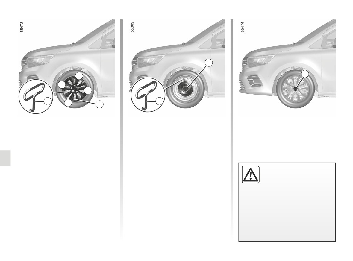
Wheel trim with concealed
Wheel trim 3
Central wheel trim with
wheel bolts
visible wheel bolts
Remove using hubcap tool 1 (located in
(Wheel trim 4)
Remove the wheel trim using hubcap
the tool kit) by engaging the hook in the
tool 1 (located in the tool kit) by en-
opening near the edge of the trim.
The bolts are directly accessible.
gaging the hook in the opening near
To refit, position the trim attachments
valve 2.
facing the wheel attachments and
To refit it, align it with valve 2. Push the
press hard in the middle of the trim to
Do not leave the tools un-
retaining hooks in fully, starting with
clip it to the wheel.
secured inside the vehicle
side A near the valve, followed by B
as they may come loose
and C, finishing at D opposite the valve.
under braking. After use,
check that all the tools are correctly
clipped into the tool kit, then position
them correctly in their housing.
Risk of injury.
5.10
CarManuals2.co
CHANGING A WHEEL (1/2)
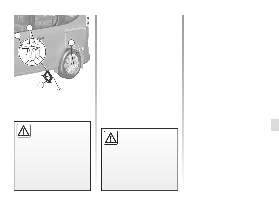
Vehicles equipped with a jack
Start cranking the jack by hand, posi-
tioning the jack support plate 1 in the
and wheelbrace
2
slightly indented groove underneath
If necessary, remove the wheel trim.
the vehicle, located between the two
1
Use the wheelbrace 3 to slacken off the
notches 2.
3
wheel bolts. Position it so as to be able
Continue to crank the jack so that the
to push from above.
baseplate is correctly positioned
(it
Position the jack 4 horizontally. The jack
should be underneath the vehicle and
head must be positioned at the same
aligned with the jack head).
level as the reinforced panel nearest to
Turn it a few times to lift the wheel off
the wheel concerned.
the ground.
4
Switch on the hazard warn-
ing lights.
If the vehicle is parked on
Keep the vehicle away from
the hard shoulder, you must
traffic and on a level surface
warn other road users of
where it will not slip.
your vehicle’s presence
with a warning triangle or with other
Apply the parking brake and set it to
devices as per the legislation apply-
P position.
ing to the country you are in.
Ask all the passengers to leave the
vehicle and keep them away from
traffic.
5.11
CarManuals2.co

CHANGING A WHEEL (2/2)
Undo the bolts and take off the wheel.
Vehicle fitted with a tyre pressure
monitoring system
Fit the emergency spare wheel on the
central hub and turn it to locate the
In the event of under-inflation (punc-
mounting holes in the wheel and the
tures, under-inflation etc.), the
hub.
warning light appears on the instrument
Tighten the bolts, checking that the
panel ➥ 2.25.
wheel is correctly positioned on its hub.
Lower the jack.
With the wheel on the ground, tighten
the bolts fully and have the tightness of
the bolts checked and the emergency
spare wheel pressure checked as soon
as possible.
Do not leave the tools unse-
cured inside the vehicle as
they may come loose under
braking. After use, ensure
that the tools are correctly placed in
their support, positioned correctly in
their housing, attach the strap, then
make sure that the tool kit access
flap is properly locked.
Risk of injury.
The jack is designed for wheel
If you have a puncture, re-
changing purposes only. Under no
place the wheel as soon as
circumstances should it be used for
possible.
carrying out repairs underneath the
A tyre which has been punc-
vehicle or to gain access to the un-
tured should always be inspected
derside of the vehicle.
(and repaired, where possible) by a
specialist.
5.12
CarManuals2.co
TYRES (1/3)
Tyre and wheel safety
Tyre pressures
The tyres are the only contact between
Adhere to the tyre pressures (including
the vehicle and the road, so it is essen-
the emergency spare wheel). The tyre
tial to keep them in good condition.
pressures should be checked at least
2
once a month and additionally before
You must make sure that your tyres
any long journey (refer to the label af-
con- form to local road traffic regula-
fixed to the edge of the driver’s door).
tions.
1
Maintaining the tyres
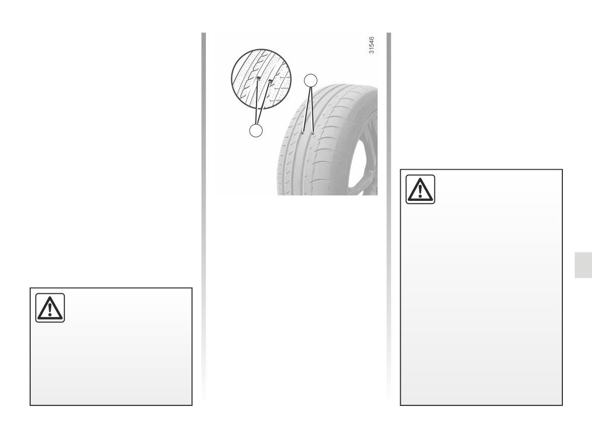
The tyres must be in good condition
and the tread form must have sufficient
depth; tyres approved by our Technical
Department have wear warning strips 1
Incorrect tyre pressures
which are indicators moulded into
lead to abnormal tyre wear
the tread at several points.
and unusually hot running.
When the tyre tread has been worn
These are factors which
to the level of the warning strips, they
may seriously affect safety and lead
become visible 2: it is then necessary
to:
to replace your tyres because the tread
rubber is now only 1.6 mm deep at
- poor road holding;
most, resulting in poor road holding
- risk of bursting or tread separa-
on wet roads.
tion.
An overloaded vehicle, long journeys
The pressure depends on the load
by motorway, particularly in very hot
Incidents which occur when
and the speed of use. Adjust the
weather, or continual driving on poorly
driving, such as striking the
pressure according to the condi-
surfaced minor roads will lead to more
kerb, may damage the tyres
tions of use (refer to the label affixed
rapid tyre wear and affect safety.
and wheel rims, and could
to the edge of the driver’s door).
also lead to misalignment of the
front or rear axle geometry. In this
case, have the condition of these
checked by an approved dealer.
5.13
CarManuals2.co

TYRES (2/3)
Pressures should be checked when the
Vehicle fitted with a tyre pressure
Fitting new tyres
tyres are cold; ignore higher pressures
monitoring system
which may be reached in hot weather
In the event of under-inflation (punc-
or following a fast journey.
tures, under-inflation etc.), the
If tyre pressures cannot be checked
warning light appears on the instrument
when the tyres are cold, assume an in-
panel, ➥ 2.25.
crease of 0.2 to 0.3 bar (or 3 PSI).
Never deflate a hot tyre.
Emergency spare wheel
For your safety, please re-
➥ 5.2, ➥ 5.11.
spect the speed limit.
When they need to be re-
Changing wheels around
placed, only tyres of the
same make, size, type and profile
This practice is not recommended.
should be used on a single axle.
They must either have a load ca-
pacity and speed rating at least
equal to those of the original
tyres, or be recommended by an
authorised dealer.
Failure to heed these instructions
could endanger your safety and
Please be aware
that
a
affect your vehicle’s roadworthi-
poorly tightened or miss-
ness.
ing valve cap can make the
Risk of loss of control of the ve-
tyres less airtight and lead
hicle.
to pressure loss.
Always use valve caps identical to
those fitted originally and tighten
them fully.
5.14
CarManuals2.co

TYRES (3/3)
Use in winter
Snow or Winter tyres
We would recommend that these be
Chains
fitted to all four wheels to ensure that
For safety reasons, fitting snow
your vehicle retains maximum adhe-
chains to the rear axle is strictly for-
sion.
bidden.
Warning: These tyres sometimes have
Chains cannot be fitted to tyres which
a specific direction of rotation and a
are larger than those originally fitted to
maximum speed index which may be
the vehicle.
lower than the maximum speed of your
vehicle.
One-way tyres
Studded tyres
An one-way tyre must only be fitted in
This type of equipment may only be
one direction. You must observe this di-
used for a limited period and as laid
rection.
down by local legislation. It is neces-
If an one-way tyre must be fitted in the
sary to observe the speed specified by
opposite to its direction of rotation fol-
17”
wheels
cannot
be
current legislation.
lowing a puncture, drive with caution,
fitted with chains.
These tyres must, at a minimum, be
particularly on a wet road, because the
If you wish to fit snow
fitted to the two front wheels.
tyre specifications will not be adapted.
chains, you must use spe-
cial equipment.
Consult an approved dealer
Chains may only be fitted
In all cases, we would recommend
to tyres of the same size
that you contact an approved Dealer
as those originally fitted to
who will be able to advise you on
your vehicle.
the choice of equipment which is
most suitable for your vehicle.
5.15
CarManuals2.co
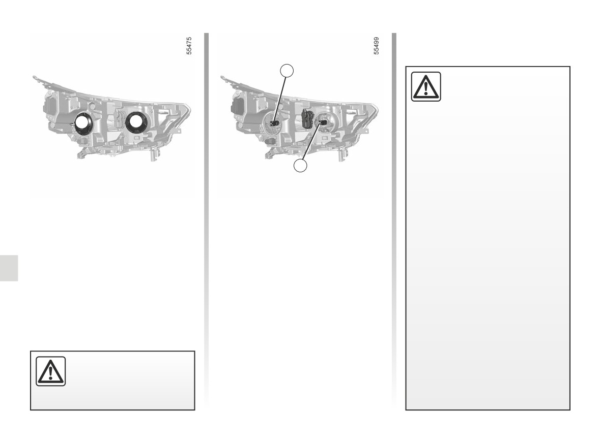
HEADLIGHTS: changing bulbs (1/2)
1
The vehicle drive system
in an electric vehicle uses
a direct voltage of approxi-
mately “400 V”.
A
B
This system can get hot during
and after switching off the ignition.
Respect warning messages given
on the labels in the vehicle.
2
Any intervention or modification
on the vehicle’s “400 V” electrical
system (components, cables, con-
nectors, traction battery) is strictly
Vehicles with halogen
Main beam headlights
prohibited.
headlights
Remove cover B.
Risk of serious injury and/or elec-
Tilt bulb holder 2 to release it and then
tric shock which may endanger
Dipped beam headlights
replace the bulb.
life.
Remove cover A.
Type of bulb: H7.
Tilt bulb holder 1 to release it and then
The engine cooling fan may also
Do not touch the bulb glass. Hold it
replace the bulb.
by its base.
start at any moment. The
Type of bulb: H7.
It is essential to use anti-U.V. 55W
label in the engine compartment re-
After replacing the bulb, please ensure
bulbs so as not to damage the plastic
minds you of this.
that the lights are adjusted by a profes-
on the headlights. Mark the bulb’s po-
Risk of injury.
sional.
sition before removal to ensure correct
positioning when replacing.
When the bulb has been changed,
make sure you refit the cover correctly.
The bulbs are under pres-
sure and can break when
replaced.
Risk of injury.
5.16
CarManuals2.co
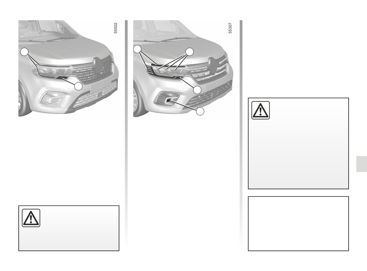
HEADLIGHTS: changing bulbs (2/2)
LED front fog lights 8
Please see an authorised dealer.
5
3
6
4
7
Any operation on (or modi-
8
fication to) the electrical
system must be performed
by an approved dealer
Daytime running lights, LED front
LED headlights
since an incorrect connection might
side lights 3
damage the electrical equipment
Daytime running lights, LED front
Please see an authorised dealer.
(harness, components and in partic-
side lights 5
ular the alternator). In addition, your
LED direction indicator lights 4
Please see an authorised dealer.
Dealer has all the parts required for
Please see an authorised dealer.
fitting these units.
LED main beam headlights, dipped
beam headlights 6
Please see an authorised dealer.
LED direction indicator lights 7
Please see an authorised dealer.
Before carrying out any op-
To comply with current legislation, or
eration in the engine com-
as a precaution, you can obtain an
partment, you must switch
emergency kit from your approved
off the ignition.
dealer containing a set of spare
bulbs and fuses.
5.17
CarManuals2.co
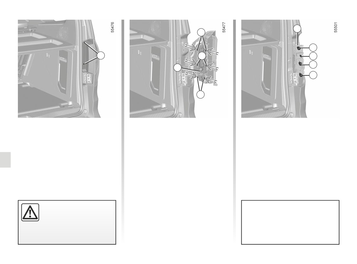
REAR LIGHTS AND SIDE LIGHTS: replacing the bulbs (1/4)
3
2
4
1
2
5
6
3
7
2
Direction indicator lights,
Release the light assembly from out-
4 Brake light
side the vehicle by pulling towards the
Bulb type 4: P21W or, depending on
reversing lights, fog lights
rear.
the vehicle, PR21W.
and brake lights
Remove the bulb holder 3 by releasing
5 Reversing light
Undo bolt 1 to remove the light.
clips 2.
Bulb type 5: W16W.
6 Indicator light
Refitting
Bulb type 6: PY21W.
To refit, proceed in the reverse order,
7 Fog light
taking care not to damage the wiring,
Bulb type 7: P21W.
and fasten clips 2 on the bulb holder 3.
The bulbs are under pres-
To comply with current legislation, or
sure and can break when
as a precaution, you can obtain an
replaced.
emergency kit from your approved
Risk of injury.
dealer containing a set of spare
bulbs and fuses.
5.18
CarManuals2.co
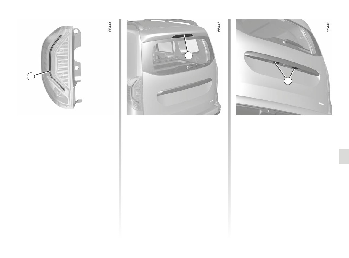
REAR LIGHTS AND SIDE LIGHTS: replacing the bulbs (2/4)
9
8
10
LED side lights 8
High-level LED brake light 9
LED number plate lights 10
(depending on the vehicle)
Consult an approved dealer.
Consult an approved dealer.
Consult an approved Dealer.
5.19
CarManuals2.co
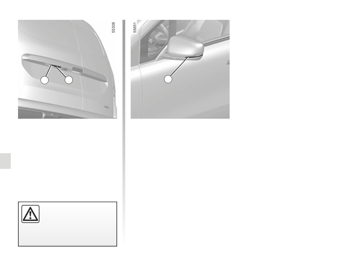
REAR LIGHTS AND SIDE LIGHTS: replacing the bulbs (3/4)
11
12
13
Number plate light
LED side repeaters 13
Undo screw 11.
Consult an approved dealer.
Remove the light cover 12 to access
the bulb.
Bulb type: W5W.
The bulbs are under pres-
sure and may break when
replaced.
Risk of injury.
5.20
CarManuals2.co
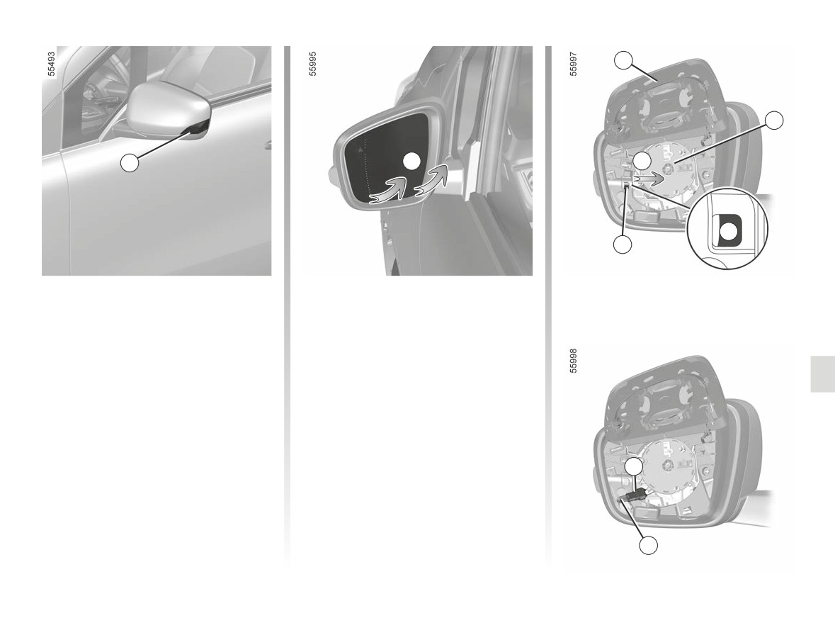
REAR LIGHTS AND SIDE LIGHTS: replacing the bulbs (4/4)
15
16
14
A
B
C
17
Indicator lights 14
Bulb type: WY5W.
As the door mirror shell needs to be
To refit it, carry out the above opera-
removed, we advise you to have the
tions in reverse order.
bulb replaced by an approved dealer.
Make sure:
To access the bulb:
- that the bulb holder 17 is aligned cor-
- carefully unclip the door mirror
rectly before inserting it into its hous-
shell
15 from its base 16 (move-
ing;
ment A);
- that the door mirror shell 15 clips
- disengage the bulb holder 17 using a
properly onto its base 16.
flat-blade screwdriver or similar, lev-
When disassembling and refitting,
ering at C (movement B);
ensure that the wiring and the surround-
- disengage and remove the bulb
ing components are not damaged.
17
holder 17 then replace the bulb 18.
18
5.21
CarManuals2.co
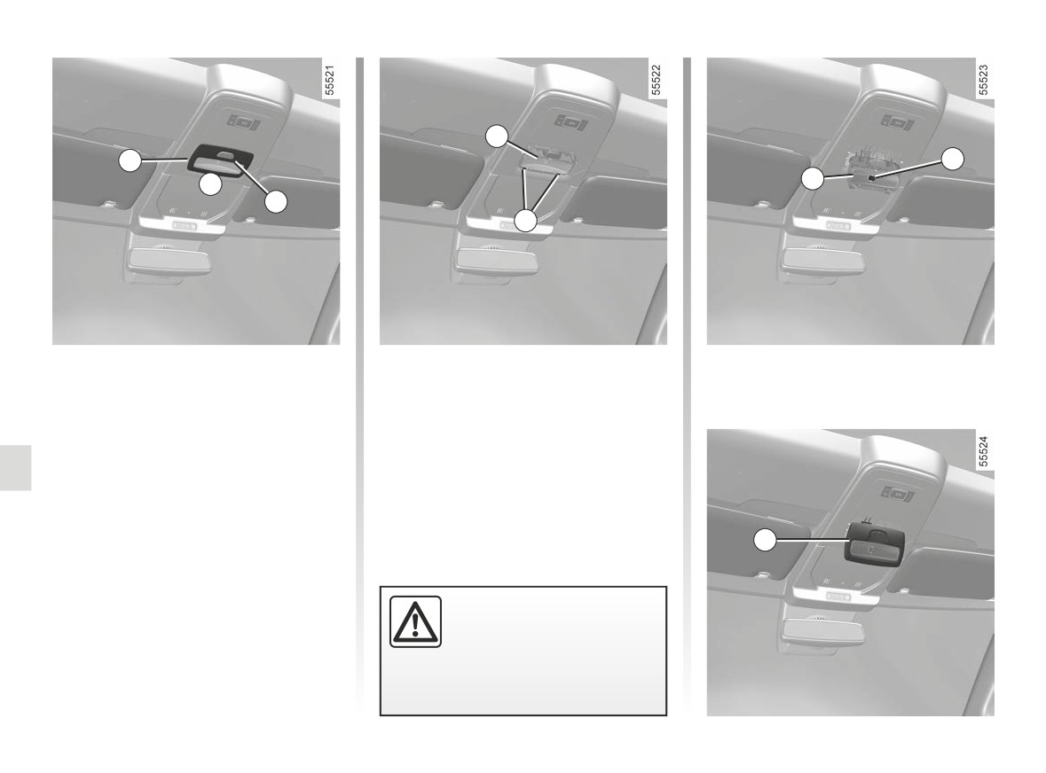
INTERIOR LIGHTING: changing bulbs (1/6)
3
1
5
3
A
2
4
Front ceiling light 1
Refitting
- Unclip the lens 2 (using a tool such
- Clip the lens 2 on to the bulb holder 3;
as a flat screwdriver), positioned
- clip in the interior lights 1 until the unit
at A;
clicks;
- unclip and release the bulb
- ensure that the interior lights are
holder 3 using the tabs 4;
properly positioned and locked into
- remove the bulb concerned.
place.
Type of bulb 5: W5W.
1
The bulbs are under pres-
sure and can break when
replaced.
Risk of injury.
5.22
CarManuals2.co