Renault Express (2023 year). Manual in english - page 4
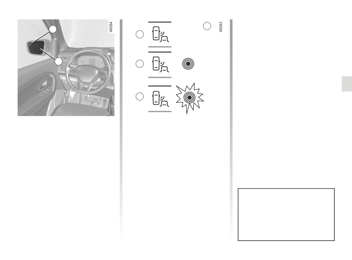
BLIND SPOT WARNING (3/4)
Display D
3
3
When the direction indicator is acti-
B
vated, the indicator light 3 flashes when
a vehicle is detected in the blind spot on
the side towards which you are about to
steer. If you cancel the direction indica-
4
tor, the function will return to the initial
C
warning (display C).
D
Indicator 3
Display B
An indicator light 3 is situated on both
The function is activated and has not
rear view mirrors 4.
detected any vehicles.
Note: clean the rear view mirrors 4 reg-
ularly so that the indicators 3 can be
Display C
seen.
First warning: the indicator 3 means
that a vehicle has been detected in the
blind spot.
The system’s detection range oper-
ates according to a standard lane
width. If you are driving in narrow
traffic lanes, it may detect vehicles
in other lanes.
2.47
CarManuals2.co
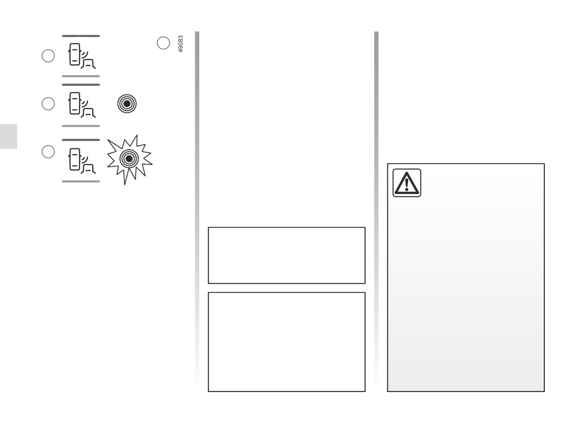
BLIND SPOT WARNING (4/4)
Operating faults
3
If the system detects a fault, the mes-
B
sage “Check blind spot alert” is dis-
played on the instrument panel. Call an
approved Dealer.
Note: when the engine is started, the
C
indicator light
3, display B, flashes
three times. It is normal.
D
-The system’s detection
range operates according
to a standard lane width. If
Conditions for non-function
you are driving in wide traf-
- If the object is not moving;
fic lanes, the system might not
- if traffic is heavy;
be able to detect a vehicle in the
blind spot.
- the road is winding;
If a trailer is attached to the vehicle,
- The system might be disrupted
- if front and rear sensors both detect
the system must be disabled with
momentarily if it is exposed to
an object at the same time (e.g.
the 2 switch.
strong electromagnetic waves
when passing an articulated lorry).
(as beneath high-tension power
- ...
lines) or to very poor weather
conditions
(heavy rain, snow
etc.). Remain aware of driving
Because sensors have been in-
conditions.
stalled in the bumpers, it is advis-
There is a risk of accidents.
able for any work (repairs, replace-
ments, touching up of paintwork
etc.) to be carried out by a qualified
professional.
2.48
CarManuals2.co
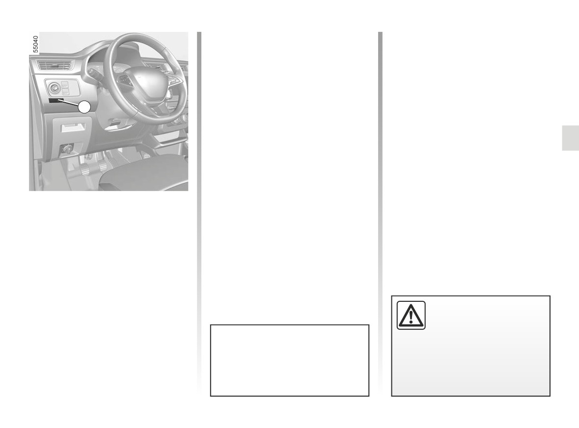
VEHICLE WITH OVERSPEED FUNCTION
Special case: if your vehicle is fitted
with the Cruise control/Speed limiter,
fully pressing the accelerator pedal
(beyond the kickdown point) will not
enable you to exceed the overspeed
function set speed. ➥ 2.30.
1
The vehicle speed may be permanently
set at a fixed value depending on the
vehicle or on local legislation.
To adjust the value or activate/deacti-
vate the function, consult an approved
dealer.
In the event of statutory limits (depend-
ing on the vehicle), this function may
not be deactivated.
Label 1 attached to the dashboard
The function does not take
shows the speed limit.
the place of the driver.
Under no circumstances
should it replace observa-
In exceptional circumstances (e.g.
tion of speed limits nor vigilance
steep gradient), the overspeed func-
and responsibility on the part of the
tion speed may be exceeded slightly
driver.
as the function does not affect the
braking system.
2.49
CarManuals2.co
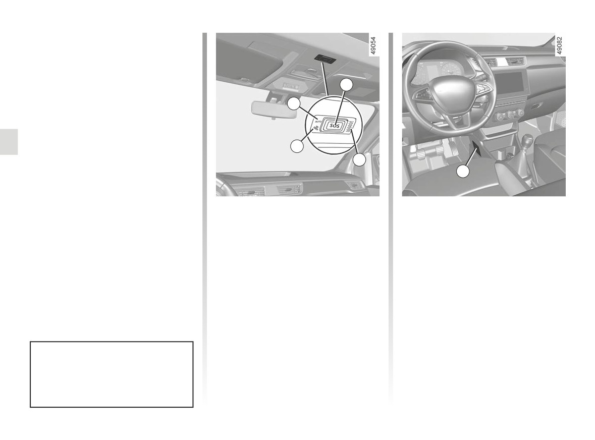
EMERGENCY CALL (1/3)
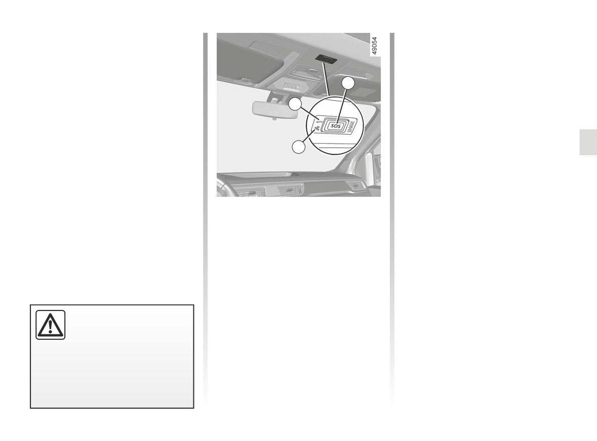
If the vehicle is equipped, the emer-
gency call function can be used to
call the emergency services (without
charge) automatically or manually in
the event of an accident or illness, re-
3
ducing the time it takes for the emer-
gency services to arrive.
2
Note: the emergency call operates:
- in countries covered by the associ-
ated telematics emergency services
1
and infrastructure compatible with
the system;
4
5
- depending on the network coverage
in the geographical region where the
vehicle is being driven.
1
System operation warning light:
A call is always made as follows:
If you use the emergency call function
– green: operational
to report an accident which you have
- the call is set up with the emergency
(network available);
witnessed, this implies stopping where
services;
- off: non-operational
traffic conditions allow in order for the
- send data related to the incident (ve-
(network unavailable);
emergency services to locate your ve-
hicle identification plate, local time
- red: operating
hicle and therefore the location of the
of the call, last positions, direction of
fault;
reported accident.
the vehicle) ;
- green flashing: call in progress.
In all cases, comply with local legisla-
2
Automatic mode warning light;
- voice communication with the emer-
tion.
3
SOS button;
gency services;
4
Microphone;
- if necessary, emergency assistance
5
Speaker.
is called.
Emergency call has two modes:
- automatic mode;
Use the emergency call only in the
event of an emergency you are in-
– Manual mode.
volved in, if you witness an accident
or if you feel ill.
2.50
CarManuals2.co
EMERGENCY CALL (2/3)
Automatic mode
In the event of unintended operation, it
is possible to cancel the call by press-
If the automatic mode 2 warning light
ing the 3 button for around two sec-
appears in green this confirms that the
onds, before the call is connected to
automatic system is activated.
the call centre.
3
The emergency call starts automati-
Once a call is established, only the call
cally in the event of an accident that
2
centre can end the call.
has required the activation of the pro-
tective equipment (seat belt pretension-
Test mode
ers, airbag etc.).
(depending on local laws)
1
Test mode is reserved exclusively for
Approved Dealers to check that the
emergency call feature is working prop-
erly.
To activate test mode:
Manual mode
- briefly press the 3 button three times;
The emergency call is carried out by:
- wait approximately 15 seconds;
- pressing and holding the 3 button for
- briefly press the 3 button three times.
at least three seconds;
Exit from test mode is automatic.
or
- pressing the
3 button five times
within ten seconds.
In the event of an acci-
dent, if the location and traf-
fic conditions permit, stay
close to the vehicle in order
to be able answer the call centre
quickly if necessary.
2.51
CarManuals2.co
EMERGENCY CALL (3/3)
The system operates with a dedi-
cated battery. The battery service
life is approximately four years
(the
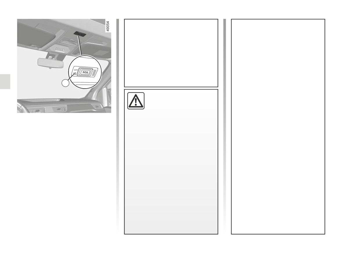
1 warning light lights up in
red to warn you when approaching
expiry).
Without the emergency call feature,
Consult an approved dealer
the system is not trackable and will
not be under constant surveillance.
1
Data is automatically and constantly
erased, and the system stores only
To guarantee your safety
the last three positions of the vehi-
and the proper operation of
cle.
the system, any operation
According to legislation relevant to
carried out on the battery
Operating faults
the country, data is only sent in the
(removal, disconnection, etc.) must
event of an emergency call. Data
In some cases, the emergency call may
be carried out by a qualified special-
sent to the call centre is treated ac-
not work (e.g. low battery).
ist.
cording to the personal data protec-
If the system detects an operating fault,
Risk of serious burns or electric
tion laws applicable in the country
the 1 warning light illuminates in red for
shocks.
where you are located. The system
more than 30 minutes. Contact your ap-
You must respect the replacement
stores activity history data for
proved Dealer as soon as possible;
intervals (without exceeding them)
13 hours only.
as stated in the maintenance docu-
The vehicle owner has the right of
ment.
access to their data. They can re-
The battery is a specific type.
quest that the data be corrected,
Please ensure it is replaced with the
deleted or locked.
same type.
Call an approved Dealer.
2.52
CarManuals2.co
Section 3: Your comfort
Air Vents
3.2
Heating, Air conditioning
3.4
Air conditioning: information and advice on use
3.8
Electric windows
3.10
Half-opening window
3.11
Interior lighting
3.12
Sun visor, Mirrors
3.14
Passenger compartment storage, fittings
3.15
Ashtrays, Cigar lighter, Accessories sockets
3.20
Rear headrests
3.22
Rear bench seat
3.24
Transporting objects in the luggage compartment
3.28
Transporting objects
3.30
towing, attachments
3.30
partition net
3.31
Luggage cover
3.32
Roof bars
3.33
Multimedia equipment
3.34
3.1
CarManuals2.co
AIR VENTS, air outlets (1/2)
3
4
5
6
2
1
7
8
7
9
1
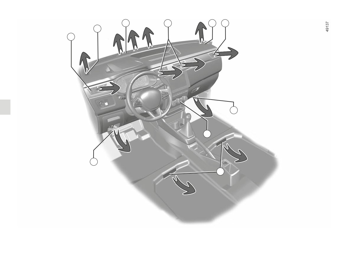
Left-hand air vent
6
Right-hand air vent
2 Left-hand side window demisting
7 Passenger footwell heater outlets
vent
8
Control panel
3
Windscreen demisting vents
9 Footwell heater outlets for rear
4
Centre air vents
passengers (depending on the
5 Right-hand side window demister
vehicle)
outlet
3.2
CarManuals2.co
AIR VENTS, air outlets (2/2)
10
10
6
9
4
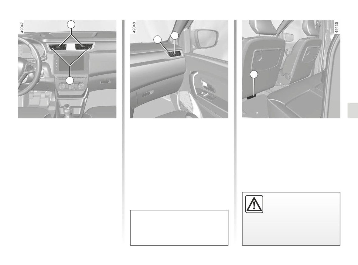
Centre 4 and side vents 1
Rear seats
and 6
(depending on vehicle)
Passenger footwell heater outlets 9.
Air flow
To close: move the cursor 10 towards
the outside of the vehicle beyond the
resistance point.
To open: move the cursor 10 towards
the inside of the vehicle.
Direction
Do not add anything to the
Move the cursor 10 to the desired po-
vehicle’s ventilation circuit
sition.
(for example, to remove
bad odours).
Do not attach any objects to the air
vents (e.g. telephone mounting).
There is a risk of damage or of
fire.
Risk of damage.
3.3
CarManuals2.co
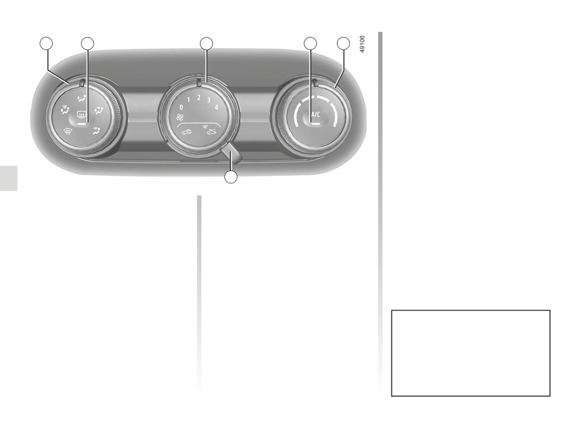
HEATING, AIR CONDITIONING (1/4)
Adjusting the air temperature
1
2
3
4
5
Turn control 5 to obtain the desired
temperature. The further towards the
red the slide is, the higher the temper-
ature will be.
Adjusting the ventilation fan
speed.
Move control 3 from 0 to 4. The further
the control is positioned to the right, the
greater the amount of air blown into the
passenger compartment. If you want to
6
shut off the flow of air completely and
switch off the system, set the control 3
to 0.
Controls
Switching air conditioning on
The controls will depend on the vehicle
or off
The system is deactivated: the ventila-
equipment level.
tion speed for the passenger compart-
The air conditioning is switched on (in-
ment air is zero (vehicle stationary),
1 Distribution of air in the passenger
dicator light lit) or off (indicator light off)
you can however still feel a slight flow
compartment.
using control 4.
of air when the vehicle is moving.
2 De-icing/demisting the rear screen
The system cannot be switched on if
and/or, depending on the vehicle, the
the control 3 is set to 0.
door mirrors.
Information and advice on use: refer
3 Adjusting the ventilation fan speed.
to information on “Air conditioning: in-
5 Air temperature adjuster.
formation and advice on use”.
6 Switching passenger compartment
Leaving this control in position 0 for
isolation mode/air recirculation mode
prolonged periods can lead to con-
on (depending on vehicle).
densation forming on the side win-
dows and windscreen and problems
due to the use of non-renewed air in
the passenger compartment.
3.4
CarManuals2.co
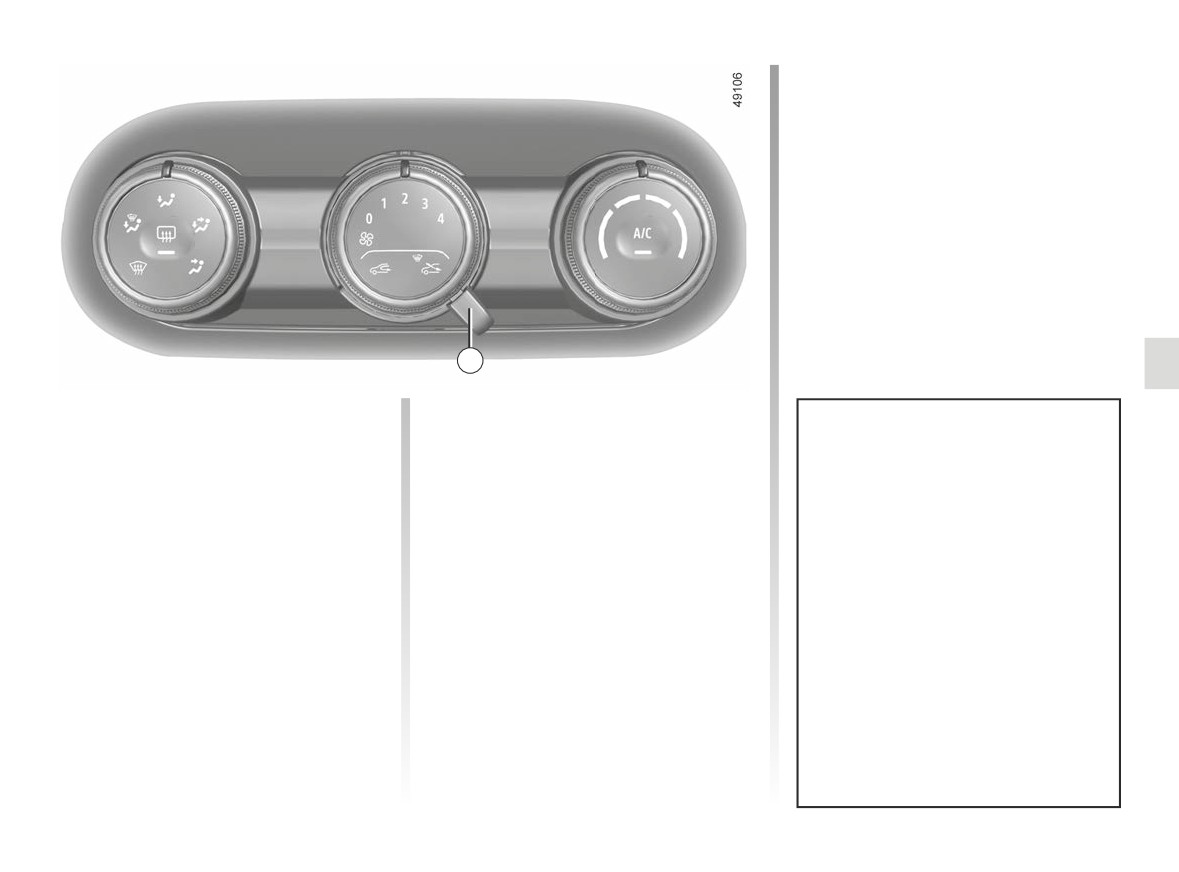
HEATING, AIR CONDITIONING (2/4)
6
Switching passenger
Air recirculation is used to:
compartment isolation mode/
- to isolate the passenger compart-
air recirculation mode on.
ment from the external atmosphere
(depending on the vehicle)
(e.g. driving in polluted areas, etc.);
Prolonged use of air recirculation
- to bring the passenger compartment
Bring lever 6 to position
â
can lead to condensation form-
to the desired temperature as quickly
Under these conditions, air is taken
ing on the side windows and wind-
as possible.
from the passenger compartment and
screen, and discomfort due to the
is recirculated, with no air being taken
use of non-renewed air in the pas-
from outside the vehicle.
senger compartment.
You are therefore advised to return
to normal mode (external air) as
soon as the air recirculation func-
tion is no longer required, by turning
control 6 to the right.
3.5
CarManuals2.co
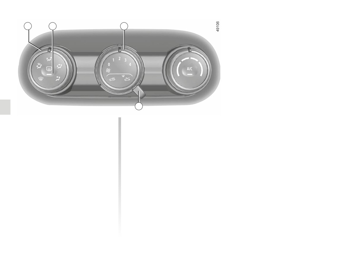
HEATING, AIR CONDITIONING (3/4)
1
2
3
6
Rapid demisting
Rear screen and/or exterior
rear view mirror de-icing/
Turn controls 1, 3 and 6 to:
demisting.
- demisting W
;
With the engine running, press
- ventilation speed 3 or 4;
button 2. The operating tell-tale comes
on.
- external air.
Depending on the vehicle, this func-
Using the air conditioning increases the
tion provides rapid demisting of the rear
speed of demisting.
screen and/or of the electric heated rear
view mirrors (on equipped vehicles).
To exit this function, press button 2
again. Warning light goes out.
Demisting automatically stops.
3.6
CarManuals2.co
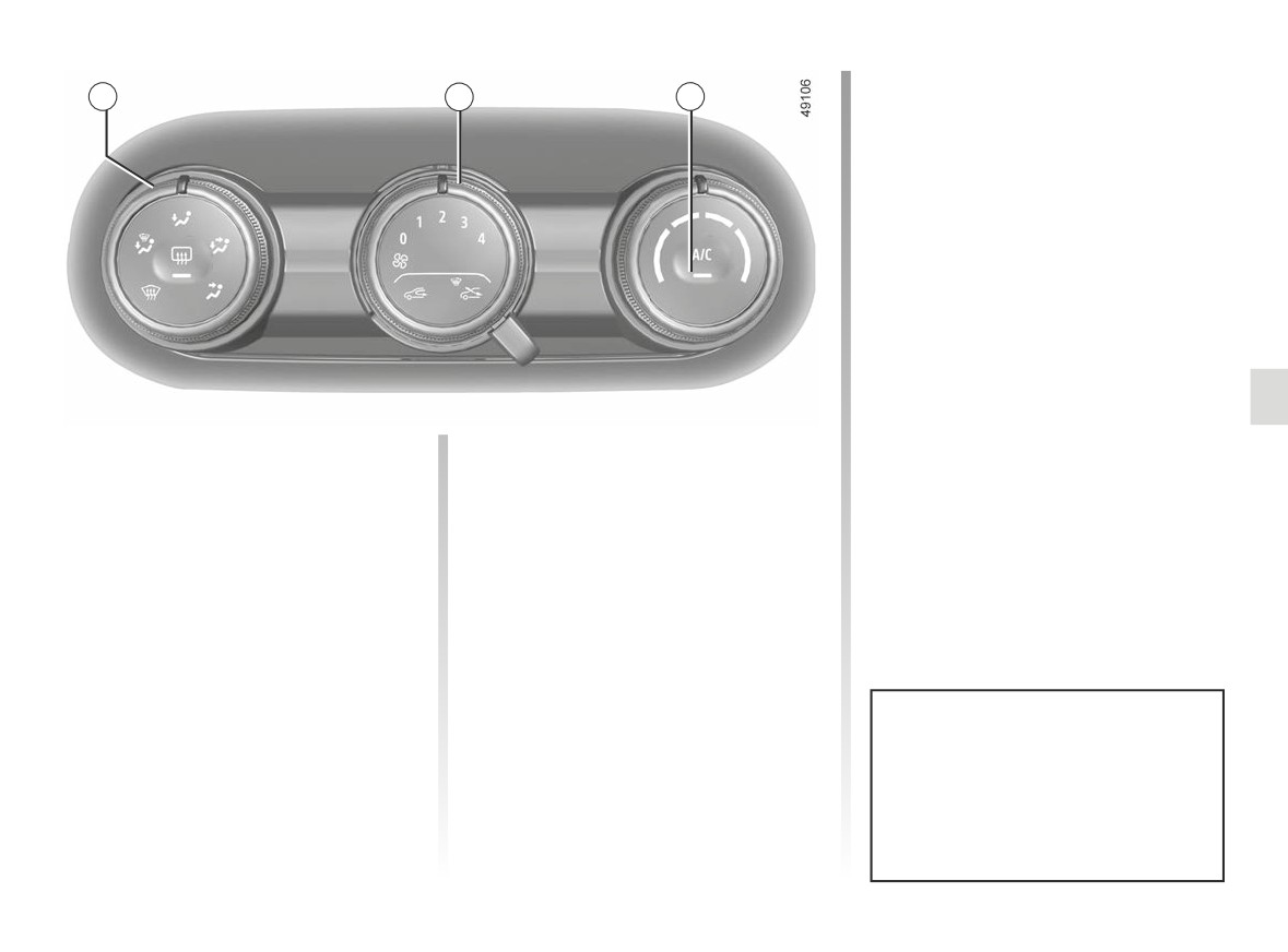
HEATING, AIR CONDITIONING (4/4)
1
3
4
Distribution of air in the
The air flow is mainly distrib-
F
uted between the front and
passenger compartment
rear footwells and the dashboard vents.
Turn control 1 to choose the distribution
Close the dashboard vents to direct all
option.
the air to the foot wells.
The air flow is mainly directed
The air flow is distributed be-
J
to the dashboard air vents.
i
tween all the air vents, the
The air flow is directed towards
front side window demisting air vents,
G
the dashboard vents and the
the windscreen demisting vents and the
footwells.
footwells.
All the air is then directed to
W
the windscreen and front side
window demisting vents.
Fuel consumption increases when
the air conditioning is being used
(switch it off when it is not required).
3.7
CarManuals2.co
AIR CONDITIONING: information and operating instructions (1/2)
Advice on use
Fuel consumption
Operating faults
In some situations (air conditioning off,
You will normally notice an increase in
As a general rule, contact your ap-
air recirculation activated, ventilation
fuel consumption (especially in town)
proved Dealer in the event of an oper-
speed at zero or low etc.), you may
when the air conditioning is operating.
ating fault:
notice that condensation starts to form
For vehicles fitted with air conditioning
- Reduction in de-icing, demisting
on the windows and windscreen.
with no automatic mode, switch off the
or air conditioning performance.
system when it is not required.
In the event of condensation, use the
This may be caused by the passen-
quick demister to remove it.
ger compartment filter cartridge be-
Advice for reducing consumption
coming clogged.
and helping to preserve the
environment
- No cold air is being produced.
Drive with the air vents open and the
Check that the controls are set cor-
windows closed. If the vehicle has been
rectly and that the fuses are sound.
parked in the sun, open the doors for a
Otherwise, switch off the system.
few moments to let the hot air escape
before starting the engine.
Presence of water under the
vehicle
Maintenance
After prolonged use of the air condi-
Refer to the Maintenance Document
tioning system, it is normal for water
for your vehicle for the inspection fre-
to be present under the vehicle. This is
quency.
caused by condensation.
Do not add anything to the
vehicle’s ventilation circuit
Do not open the refriger-
(for example, to remove
Use the air conditioning system reg-
ant circuit. The fluid may
bad odours).
ularly, even in cold weather, running
damage eyes or skin.
There is a risk of damage or of
it at least once a month for approxi-
fire.
mately 5 minutes.
3.8
CarManuals2.co
AIR CONDITIONING: information and operating instructions (2/2)
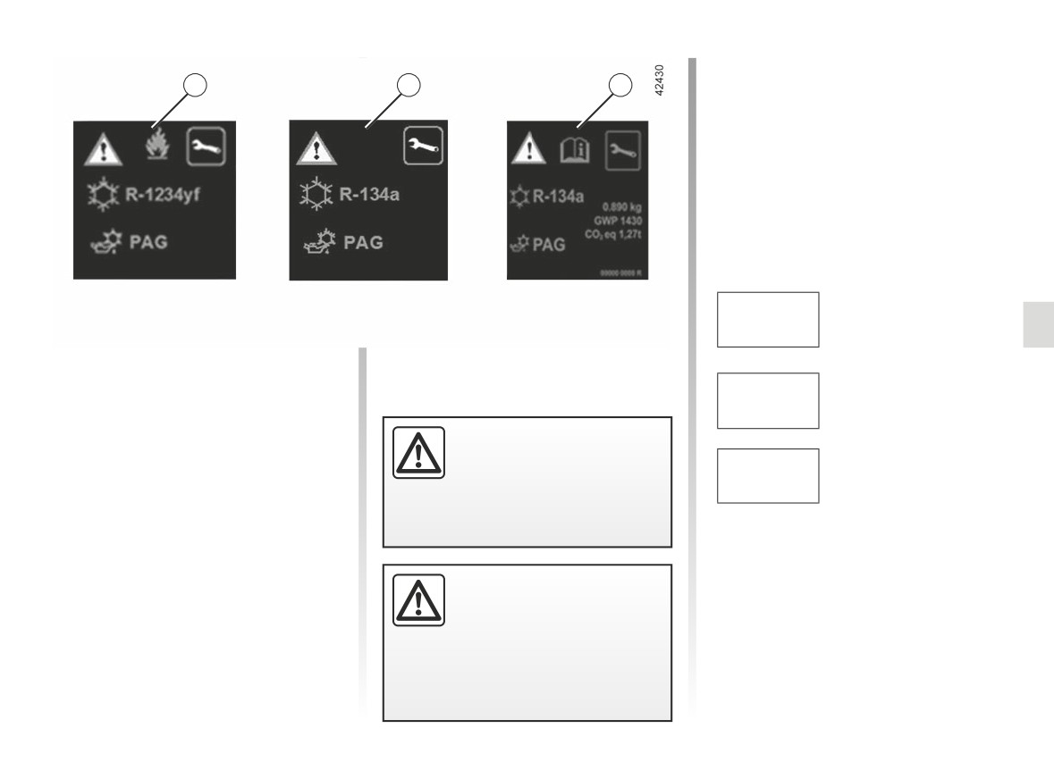
Type of refrigerant fluid
Ñ
A
A
A
Type of oil in the air condi-
tioning circuit
Inflammable product
Consult the driver’s hand-
book
Maintenance
Quantity of refrigerant
x.xxx kg
fluid present in the ve-
hicle.
The refrigerant fluid circuit (of which
some components are hermetically
Global
Warming
sealed) may contain fluorinated green-
GWP xxxxx
Potential (CO2 equiv-
house gases.
alent).
Do not open the refriger-
Depending on the vehicle, you will find
ant circuit. The fluid may
the following information on label A af-
CO2 eq
Quantity in weight and
damage eyes or skin.
fixed inside the engine compartment.
x.xx t
in CO2 equivalent.
The presence and location of the infor-
mation on label A depends on the ve-
hicle.
Before carrying out any
action in the engine com-
partment, you must switch
off the ignition. ➥ 2.3.
3.9
CarManuals2.co
ELECTRIC WINDOWS (1/2)
Driver’s responsibility
3
Never leave your vehicle
1
with the key inside, and with
a child, a dependent adult
or a pet, even for a short while.
2
They may pose a risk to themselves
or to others by starting the engine
or activating equipment (such as the
Electric windows
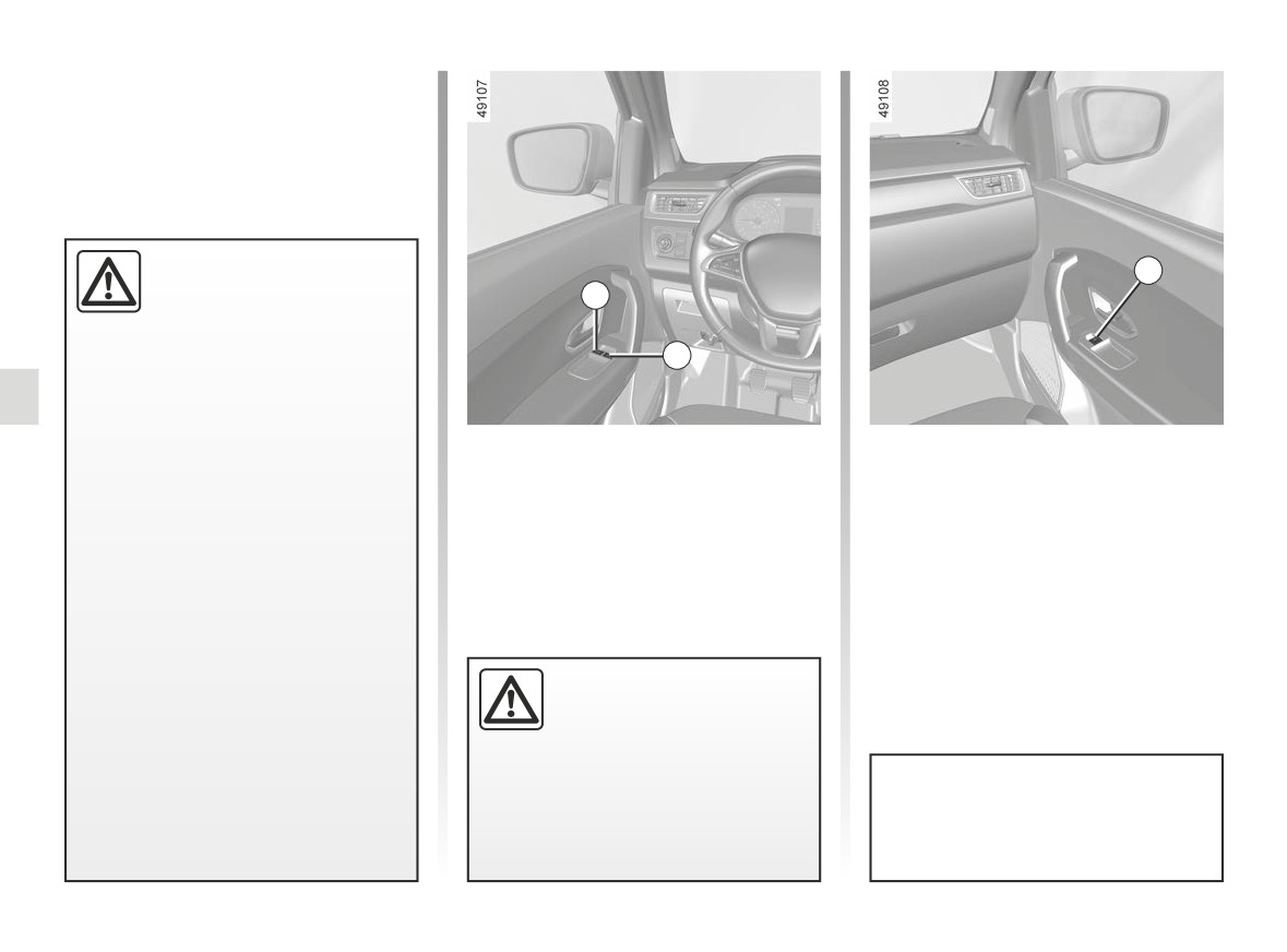
From the driver’s seat, use switch:
gear lever or electric windows).
Press the window switch down or lift it
1 for the driver’s side;
If any part of the body becomes
2 for the front passenger side.
up to lower or raise the window to the
trapped, reverse the direction of the
desired height.
From the front passenger seat, move
window immediately by pressing the
switch 3.
relevant switch.
Risk of serious injury.
When closing the windows,
ensure that no part of the
body (arm, hand, etc.) is
protruding from the vehicle.
Risk of serious injury.
Avoid resting any objects against a
half-open window: there is a risk that
the electric window winder could be
damaged.
3.10
CarManuals2.co
ELECTRIC WINDOWS (2/2)
One-touch electric windows
Operating faults
When the vehicle is equipped with this
In case of a fault when closing a
function, the one-touch mode works in
window, the system reverts to normal
addition to the operation of the electric
mode: pull the switch concerned up as
4
windows described previously.
often as necessary to fully close the
window (the window will close gradu-
It is only fitted to the driver’s window.
ally), hold the switch (still on the clos-
A
- Fully and briefly press down on the
ing side) for one second then lower and
relevant switch down: the window
raise the window fully to reinitialise the
will open completely.
system.
- Fully and briefly lift the relevant
If necessary, contact an approved
switch: the window will close com-
Dealer.
pletely.
Pressing the switch again while the
window is moving will stop its move-
ment.
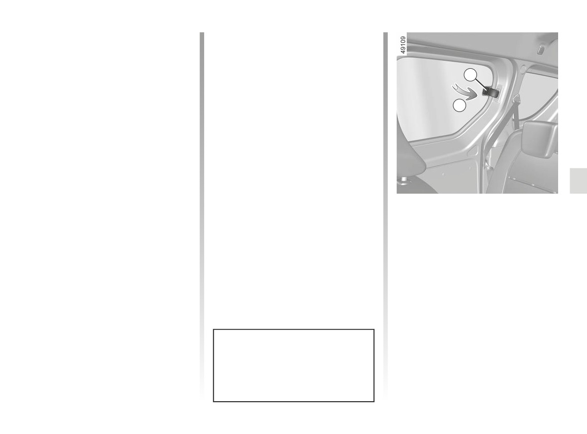
Half-opening window
Note: if the window meets resistance
To half-open the window, turn handle 4
when closing (e.g. tree branch), it stops
(movement A) then lock it by pushing
and then lowers again by a few centi-
the handle to the right.
metres.
Make sure it is properly latched into po-
If you use the switch while the window
sition when it is closed.
is moving, it stops working.
Avoid resting any objects against
a half-open window: there is a risk
that the electric window could be
damaged.
3.11
CarManuals2.co
INTERIOR LIGHTING (1/2)
1
2
1
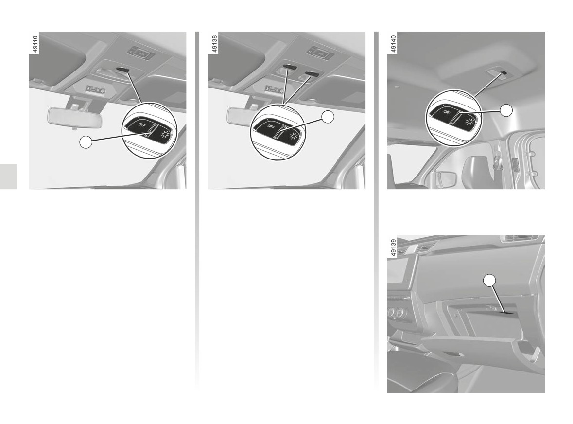
Courtesy light
Map reading lights
(depending on vehicle)
Pressing switch 1 provides:
Pressing switch 2 provides:
- continuous lighting;
- continuous lighting;
- or temporary lighting by opening one
- or temporary lighting by opening one
of the front doors, or by opening one
of the front doors, or by opening one
of the four doors, depending on the
of the four doors, depending on the
vehicle. The light only goes out when
vehicle. The light only goes out when
the doors are correctly closed;
3
the doors are correctly closed;
– no lighting.
- no lighting.
Glovebox light 3
Light 3 comes on when the cover is
opened.
3.12
CarManuals2.co
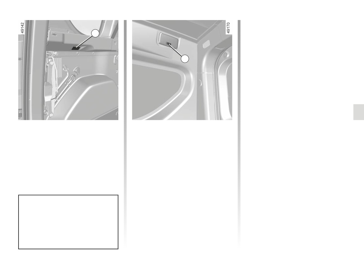
INTERIOR LIGHTING (2/2)
Special features
Depending on the vehicle, remote un-
4
locking of the doors triggers timed light-
ing of the passenger compartment. If
one of the front or rear doors is opened,
5
the period for which the light is switched
on will start again.
Then the courtesy light and the luggage
compartment light dim and go out.
The lighting timer will cut out for various
reasons:
-
if a door has been open for 15 min-
utes;
-
if all the doors have been closed for
Boot light 4
Rear light
15 seconds or 5 minutes, depending
on the vehicle;
Light 4 comes on when the luggage
Turning the switch 5 gives you:
compartment is opened.
-
when the ignition is switched on.
– continuous lighting;
- or temporary lighting, controlled by
opening one of the front doors, or
by opening one of the four doors,
depending on the vehicle. The light
only goes out when the doors are
correctly closed;
- or else the light definitively turned
off.
When the doors or luggage com-
partment are unlocked and opened
the courtesy and footwell lights
come on temporarily.
3.13
CarManuals2.co
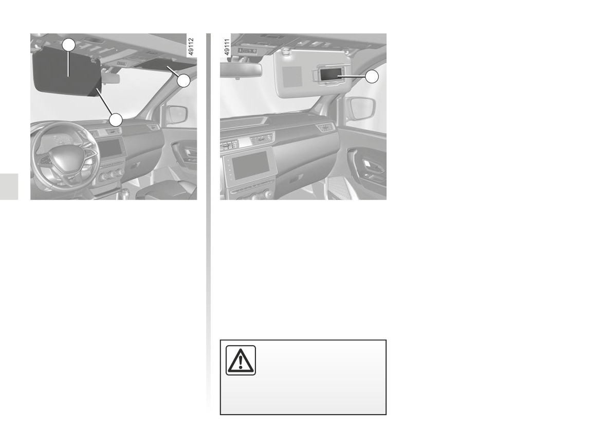
SUN VISOR, MIRRORS
1
4
2
3
Front sun visor
Courtesy mirror 4
(passenger side)
Lower the sun visor 1 or 2 over the
windscreen or unclip it and turn it over
the side window.
Sun visor storage 3
Can be used to hold motorway toll tick-
ets, maps, etc.
When driving, ensure the
courtesy mirror cover is
closed.
Risk of injury.
3.14
CarManuals2.co
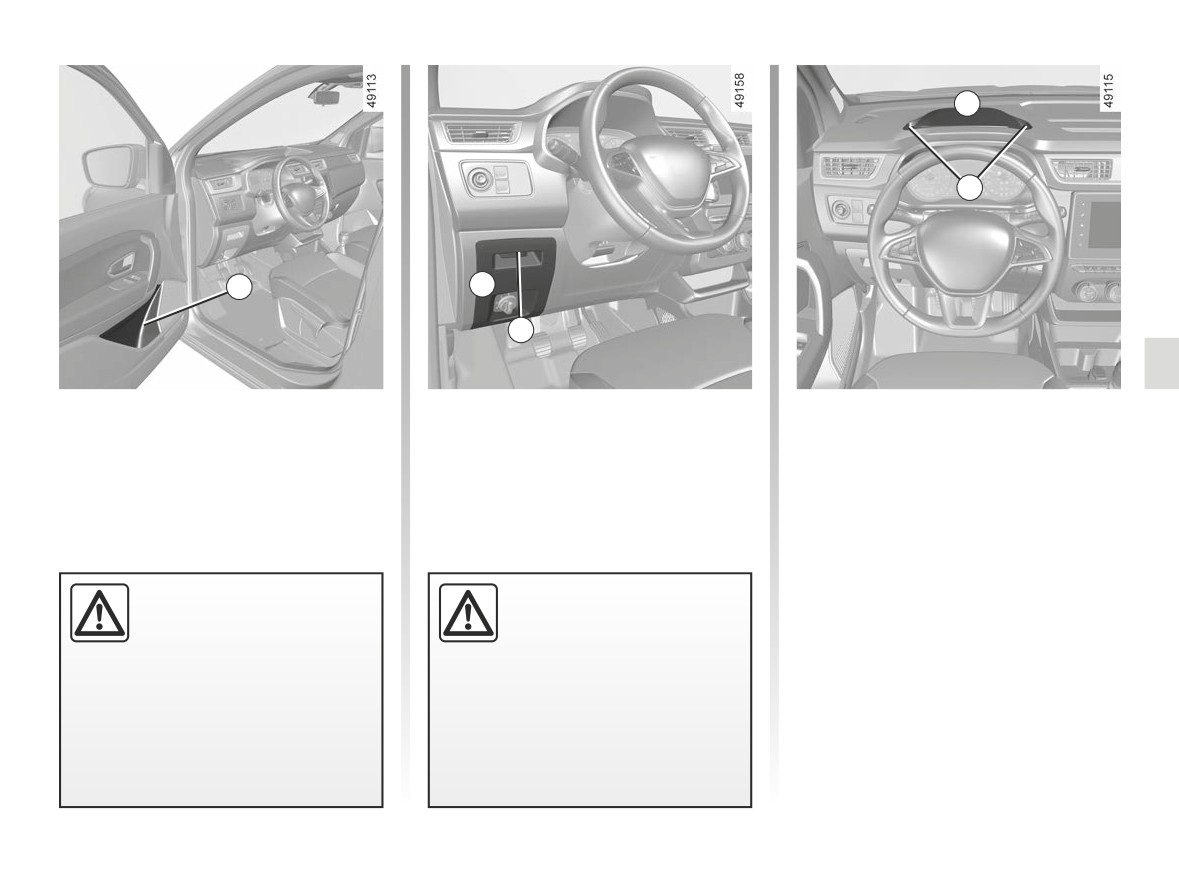
PASSENGER COMPARTMENT STORAGE SPACE AND FITTINGS (1/5)
B
3
1
A
2
Door pockets 1
Storage compartment A
Driver’s dashboard upper
storage compartment B
Unlock the handle 2 and pull to open
the storage compartment A.
Put a hand in location 3 and lift to open
the storage compartment B.
It is recommended that you open the
storage compartment only when the ve-
hicle is stationary.
Nothing should be placed
Ensure that no hard, heavy
on the floor area in front of
or pointed objects are
the driver as such objects
placed in the “open” storage
may slide under the pedal
compartments in such a
during braking manoeuvres, thus
way that they may fall onto passen-
obstructing its use.
gers during sudden turning, braking
or in the event of an accident.
3.15
CarManuals2.co
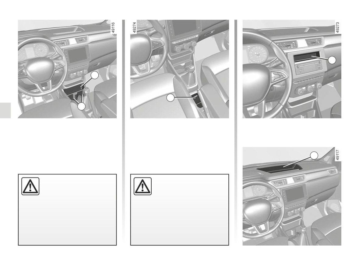
PASSENGER COMPARTMENT STORAGE SPACE AND FITTINGS (2/5)
7
4
6
5
Storage compartment 4
Central storage
compartment 6
Cup holder 5
Storage compartment 7
8
Dashboard storage 8
When turning corners,
Ensure that no hard, heavy
accelerating or braking,
or pointed objects are
ensure that the recepta-
placed in the “open” storage
cle being held by the cup
compartments in such a
holder is not dislodged.
way that they may fall onto passen-
gers during sudden turning, braking
There is a risk of injury if hot
or in the event of an accident.
liquid escapes.
3.16
CarManuals2.co
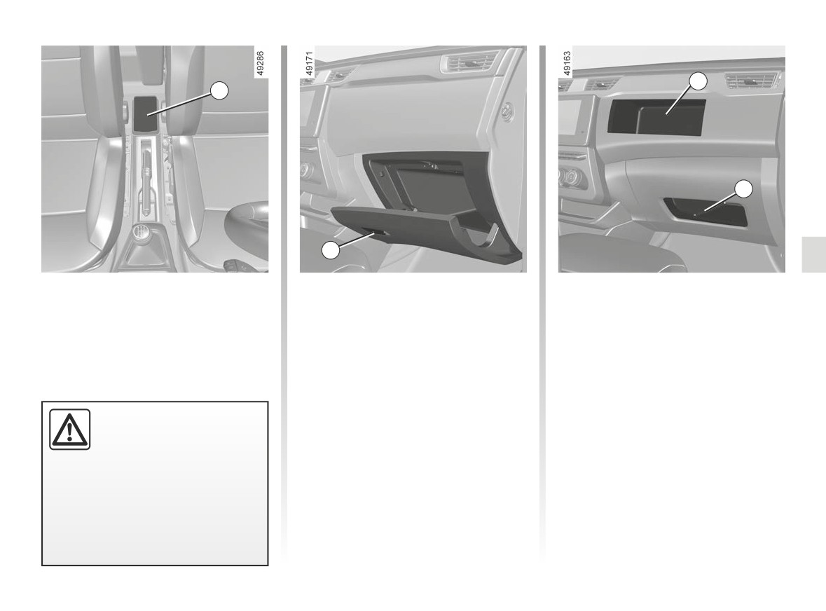
PASSENGER COMPARTMENT STORAGE SPACE AND FITTINGS (3/5)
11
9
12
10
Centre console storage
Glove box
Passenger storage
compartment/Wireless
compartment 11 and 12
If fitted on the vehicle, pull paddle 10 to
charger - induction
open.
charging 9
For more information on the induction
charging area ➥ 3.34.
Ensure that no hard, heavy
or pointed objects are
placed in the “open” storage
compartments in such a
way that they may fall onto passen-
gers during sudden turning, braking
or in the event of an accident.
3.17
CarManuals2.co
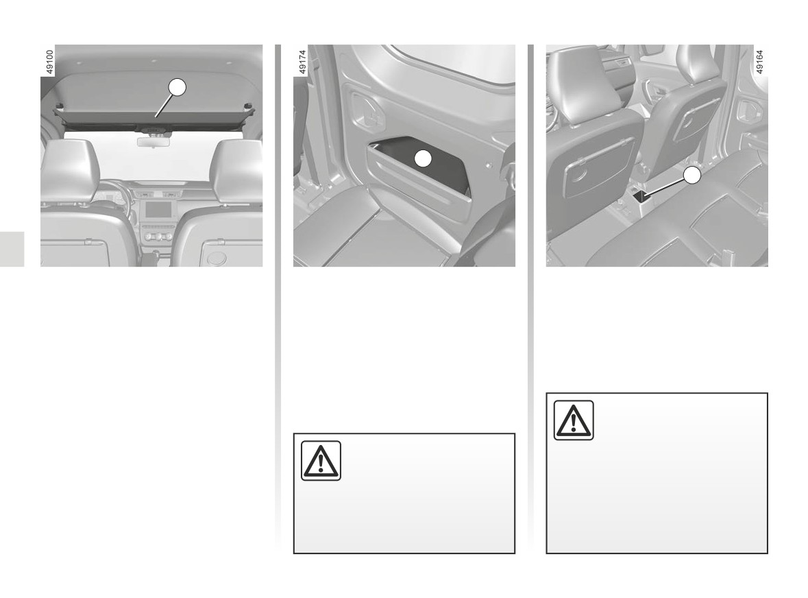
PASSENGER COMPARTMENT STORAGE SPACE AND FITTINGS (4/5)
13
14
15
Front upper cab storage
Sliding side door storage
Cup holder 15
compartment 13
compartment 14
Do not use it for getting into or out of the
Items stored in the sliding side door
vehicle and do not hang from it.
storage compartments should not stick
out from the storage compartment, so
The total weight of the upper cab stor-
as not to hamper the sliding of the door.
age compartment 13 must not exceed
4.6 kg, evenly distributed.
Do not place wet items or containers
When turning corners,
with liquid in them in the upper cab stor-
accelerating or braking,
age compartment.
ensure that the recepta-
Do not hang any heavy and/
cle being held by the cup
or sharp objects which may
holder is not dislodged.
fall whilst driving.
There is a risk of injury if hot
Risk of injury.
liquid escapes.
3.18
CarManuals2.co
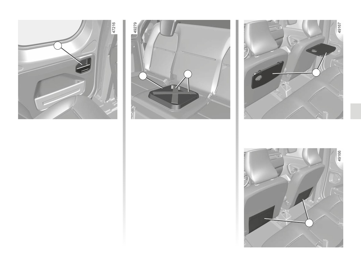
PASSENGER COMPARTMENT STORAGE SPACE AND FITTINGS (5/5)
16
18
19
17
Storage compartment 16
Rear bench seat central
storage compartment 17
Retaining straps 18
They can be used, for example, to
retain a multimedia tablet etc.
Rear parcel shelves 19
Raise them to their horizontal position.
Front seat storage pockets 20
20
3.19
CarManuals2.co
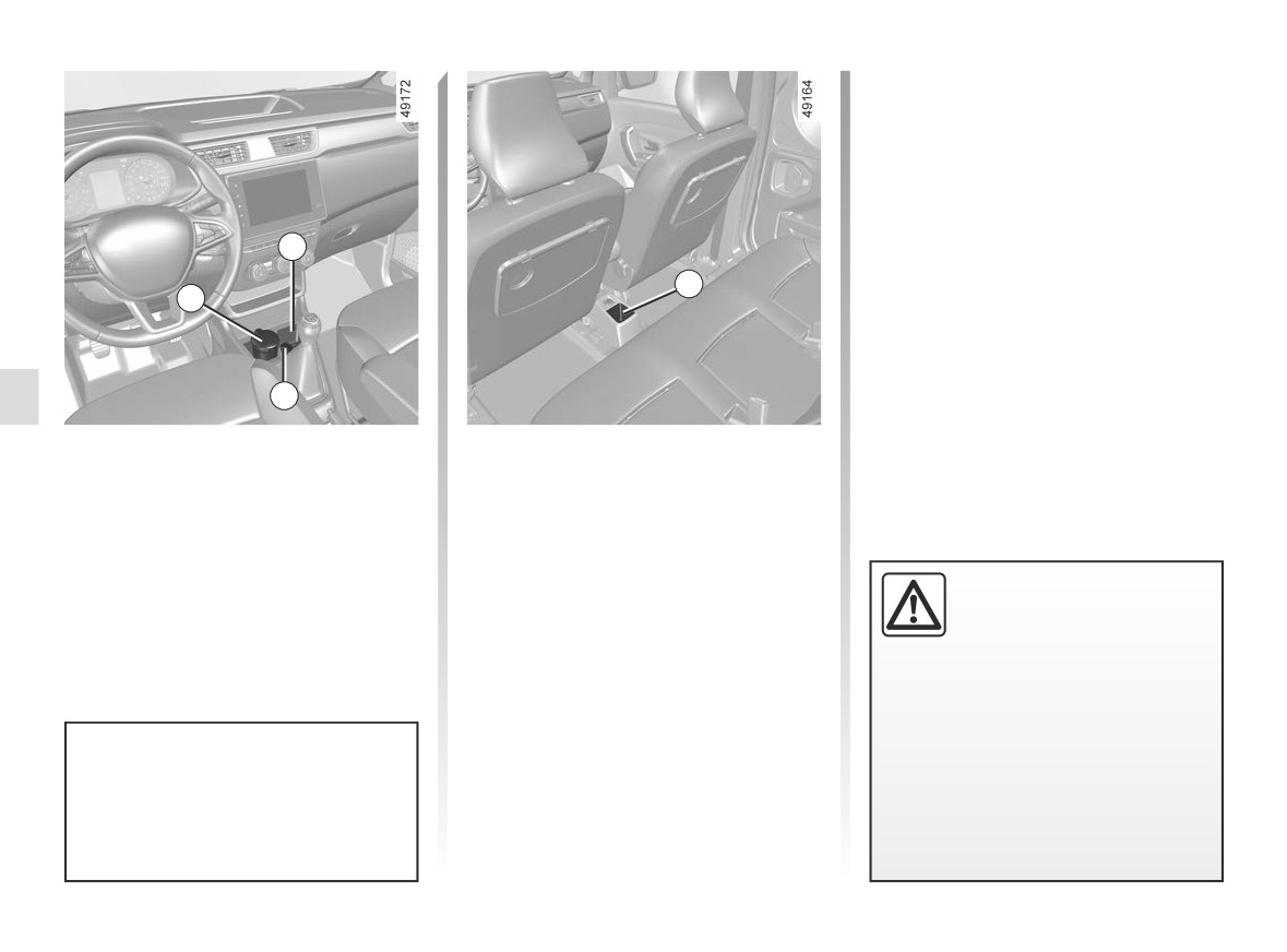
ASHTRAY, CIGARETTE LIGHTER, ACCESSORIES SOCKET (1/2)
2
4
1
3
Ashtray 1
Cigarette lighter or
accessories socket 3
It can be housed in location 2 or 4.
Lift the cover to open.
With the ignition on, push in the ciga-
rette lighter 3. It will spring back with a
To empty, pull the ashtray towards you
click when it is ready. Pull it out to use.
and it will be released from its housing.
After use, replace it without pushing it
Only connect accessories
all the way in.
of maximum power
120
watts (voltage 12 V).
When several accessory
sockets are used at the same time,
the total power of the connected
accessories must not exceed
180 watts.
If your vehicle is not fitted with a
Fire hazard.
cigar lighter and an ashtray, these
can be obtained from an approved
Dealer.
3.20
CarManuals2.co
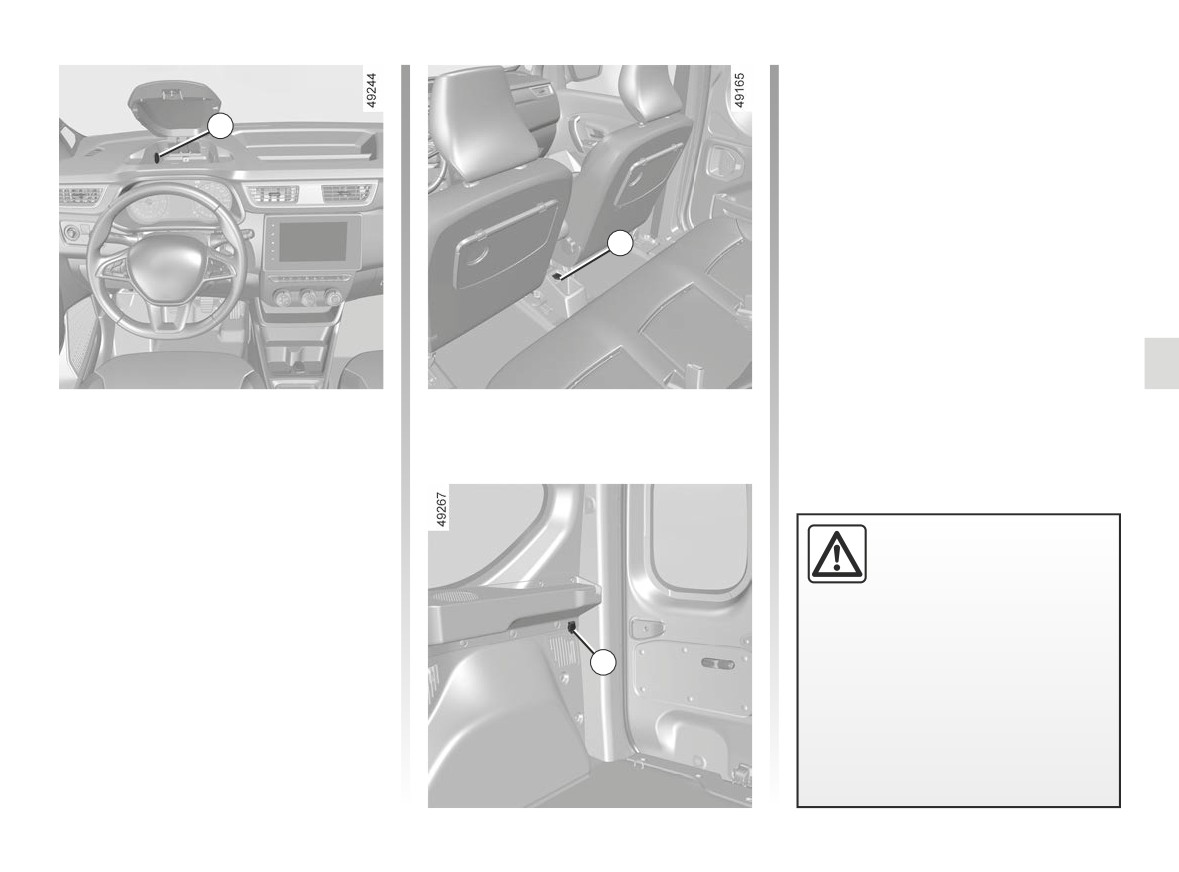
ASHTRAY, CIGARETTE LIGHTER, ACCESSORIES SOCKET (2/2)
5
6
Accessories socket 5, 6 and 7
(depending on the vehicle)
They are provided for connecting ac-
cessories approved by our Technical
Department.
Only connect accessories
of maximum power
120
watts (voltage 12 V).
When several accessory
sockets are used at the same time,
the total power of the connected
7
accessories must not exceed
180 watts.
Fire hazard.
3.21
CarManuals2.co
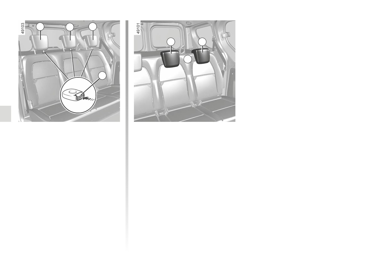
REAR HEADRESTS (1/2)
1
1
1
1
1
A
2
Five-seater version
To put the headrest back in place 1
Insert the rods into the holes, press the
Position for using headrest 1
tab(s) 2 and lower the headrest.
Lift the headrest fully until it locks.
Check that the bonnet is correctly
Check that the bonnet is correctly
locked.
locked.
Headrest 1 storage position A
To raise the headrest 1
Press tab 2 and lower the headrest fully.
Raise the headrest as far as it will go,
When the headrest is set at the
then press tab(s) 2 and remove the
lowest position, Athis is for storage
headrest.
only: it should not be in this position
when a seat is occupied.
3.22
CarManuals2.co
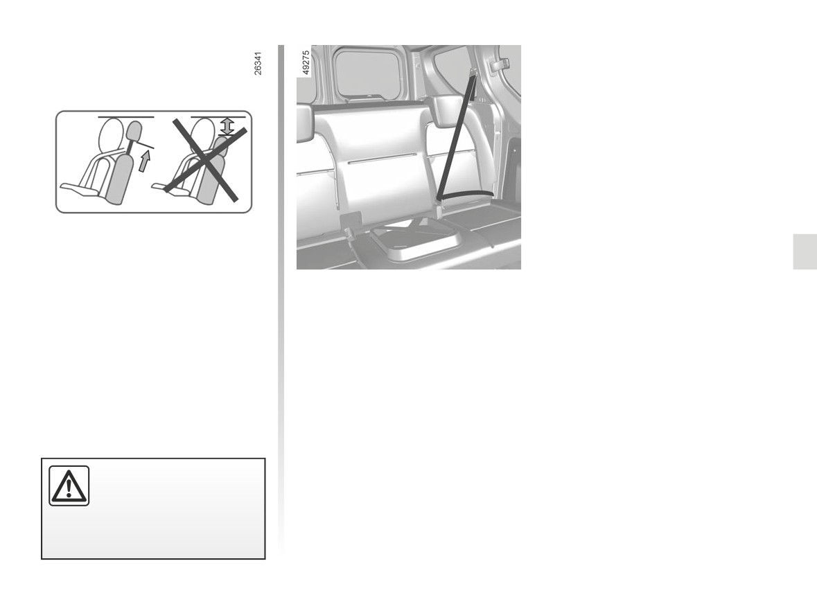
REAR HEADRESTS (2/2)
Four-seater version
This version differs in that it has rear
seatbelts and headrests on the rear
side seats only.
The headrest is a safety
component; check that it is
fitted and in the correct po-
sition.
3.23
CarManuals2.co
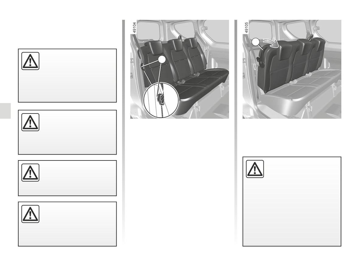
REAR BENCH SEAT: functions (1/4)
2
When moving the rear
1
seats, ensure that nothing
obstructs the anchorage
points (passenger’s arm or
leg, a pet, gravel, cloth, toys, etc.).
Check that the rear seat
belts are positioned and
Fixed rear bench seat
To reposition the seatback
operating correctly each
- Lift the seat back;
time the rear bench seat is
To fold down the seatback
- make sure you lock the seat back in
moved.
place.
- Bring the front seats forward;
- lower the headrests;
- insert the rear seatbelt buckle in
When refitting the seat-
For safety reasons, carry
housing 1;
back, make sure it is cor-
out any adjustments when
rectly locked in place.
the vehicle is not being
- pull handle 2;
If seat covers are fitted,
driven.
- lower the seatback onto the seat
make sure these do not prevent the
base;
seatback latch from locking in.
Make sure that the seat belts are
– adjust the front seats.
To avoid all risk of injury,
positioned correctly.
ensure that nobody is close
Reposition the headrests.
to the moving parts.
3.24
CarManuals2.co
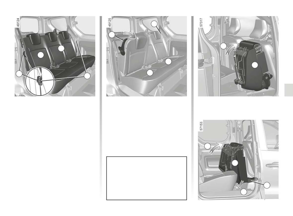
REAR BENCH SEAT: functions (2/4)
2
2
C
B
A
B
A
1
A
1
Five-seater version
- lift the A seat or the bench seat B
until it is positioned vertically (move-
Rear bench seat with folding seat
ment C);
back and seat cushion
- adjust the front seats, making sure
they are properly locked in place.
To fold down the seat A or the bench
seat B:
Depending on the vehicle, you may
– Bring the front seats forward;
need to guide the bench seat into the
– insert the rear side seat belt buckles
folded position B (movements C and D)
into their 1 housings;
to ensure that once folded it does not
C
- lower the headrest(s) ➥ 3.22;
interfere with the wireless charger 3.
- pull handle 2;
- lower the seatback onto the seat
base;
B
Special note for five-seater ver-
sions
Installing an ISOFIX seat in the rear
centre seat will prevent the rear side
3
seat from folding.
D
3.25
CarManuals2.co
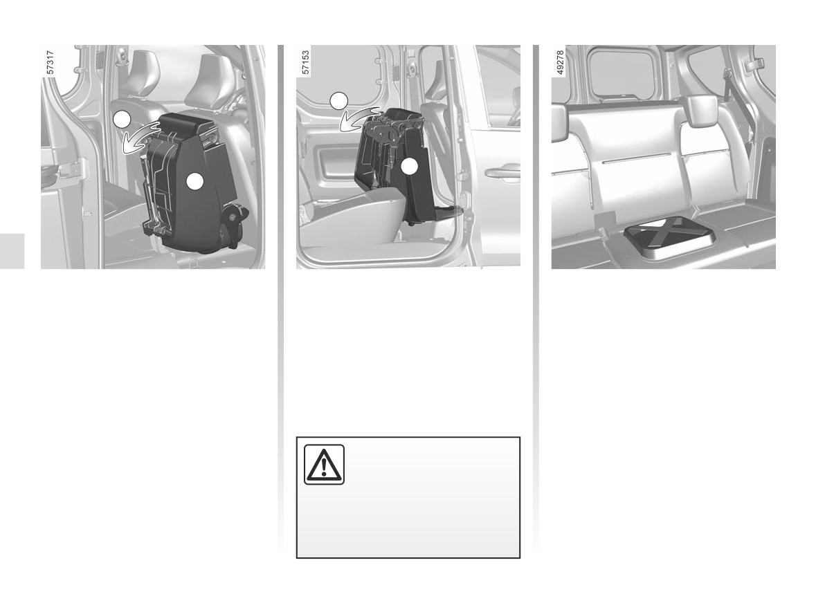
REAR BENCH SEAT: functions (3/4)
E
E
B
A
To reposition the seat A or the
Four-seater version:
bench seat B:
This version differs in that it has rear
- Lower the seat base until it locks
seatbelts and headrests on the rear
(movement E);
side seats only.
- Lift the seat back;
- make sure that the seat bases and
seatbacks lock into position cor-
rectly;
- adjust the front seats, making sure
they are properly locked in place.
Make sure that the seat-
back is correctly locked. If
necessary, remove any ob-
stacles behind the seats.
Repeat the above until the seat is
locked correctly.
3.26
CarManuals2.co
REAR BENCH SEAT: functions (4/4)
F
Check that the rear seat
belts are positioned and
operating correctly each
time the rear bench seat is
moved.
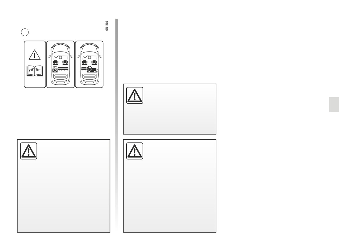
Restriction of use
It is illegal to drive with one
When refitting the seat-
of the second row seats
back, make sure it is cor-
folded down if a passenger
rectly locked in place.
is sitting in the other seat of
If seat covers are fitted,
the second row.
make sure these do not prevent the
seatback latch from locking in.
The label F in the vehicle reminds
Make sure that the seat belts are
you of this.
positioned correctly.
Risk of injury.
Reposition the headrests.
3.27
CarManuals2.co
TRANSPORTING OBJECTS IN THE BOOT (1/2)
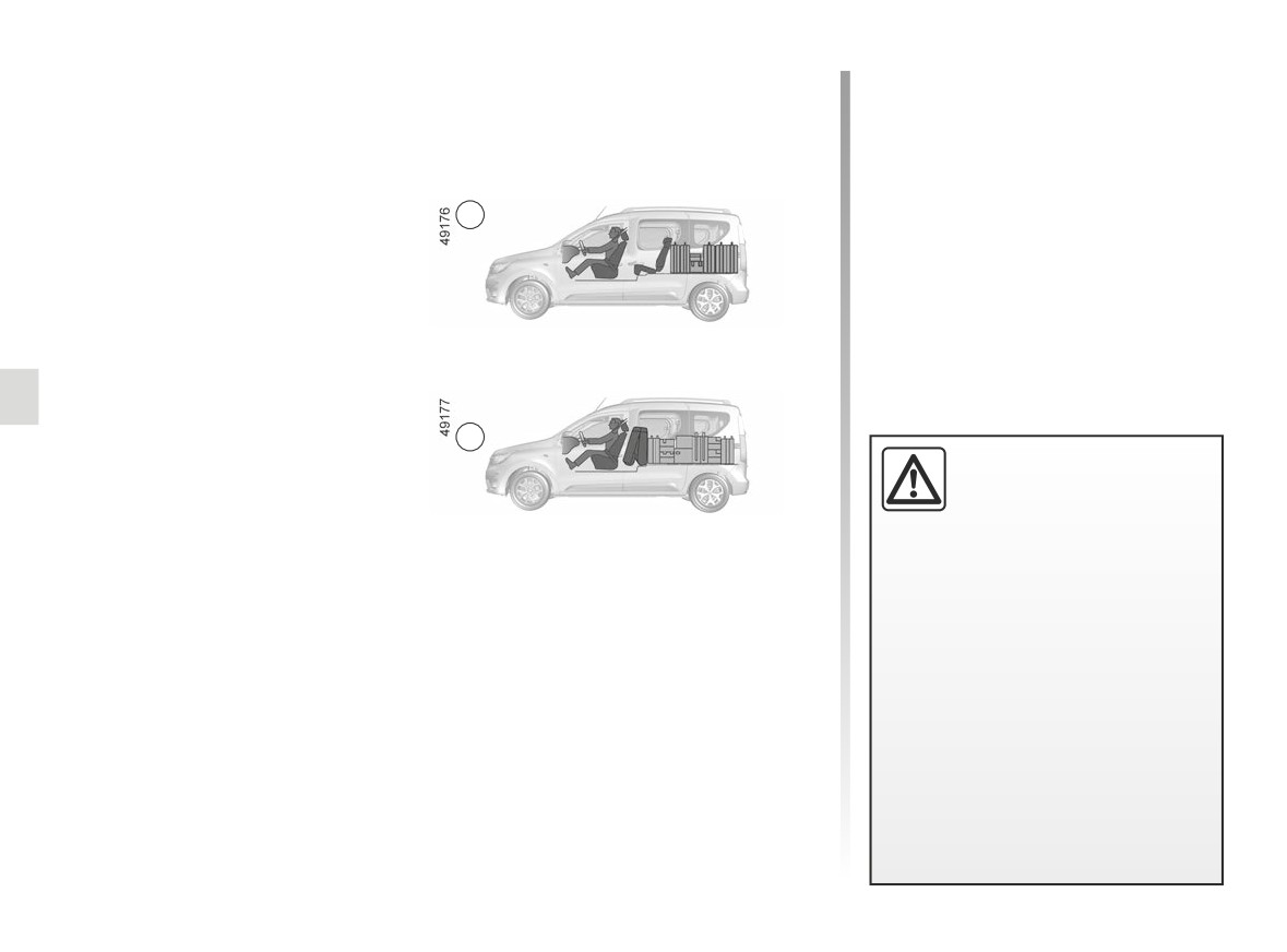
Always position the objects trans-
ported so that the largest surface is
against:
A
- the rear bench seatbacks, for
normal loading (example A);
- the front seatbacks with the rear
seatbacks folded down, as is the
B
case for maximum loads (exam-
Always position the heavi-
ple B) ➥ 3.24.
est items directly on the
floor. Use the lashing points
on the luggage compart-
ment floor, if these are fitted to the
vehicle. The load should be loaded
in such a way that no items will be
Ensure that the objects being trans-
thrown forward and strike the occu-
ported are evenly distributed through-
pants if the driver has to brake sud-
out the loading area.
denly or while driving on a steep
If you have to place objects on the
gradient. Fasten the rear seat belts,
folded seat back, it is vital that you
even if the seats are not occupied.
remove the headrests before folding the
seat back so that it can be folded as flat
as possible against the seat.
3.28
CarManuals2.co
TRANSPORTING OBJECTS IN THE BOOT (2/2)
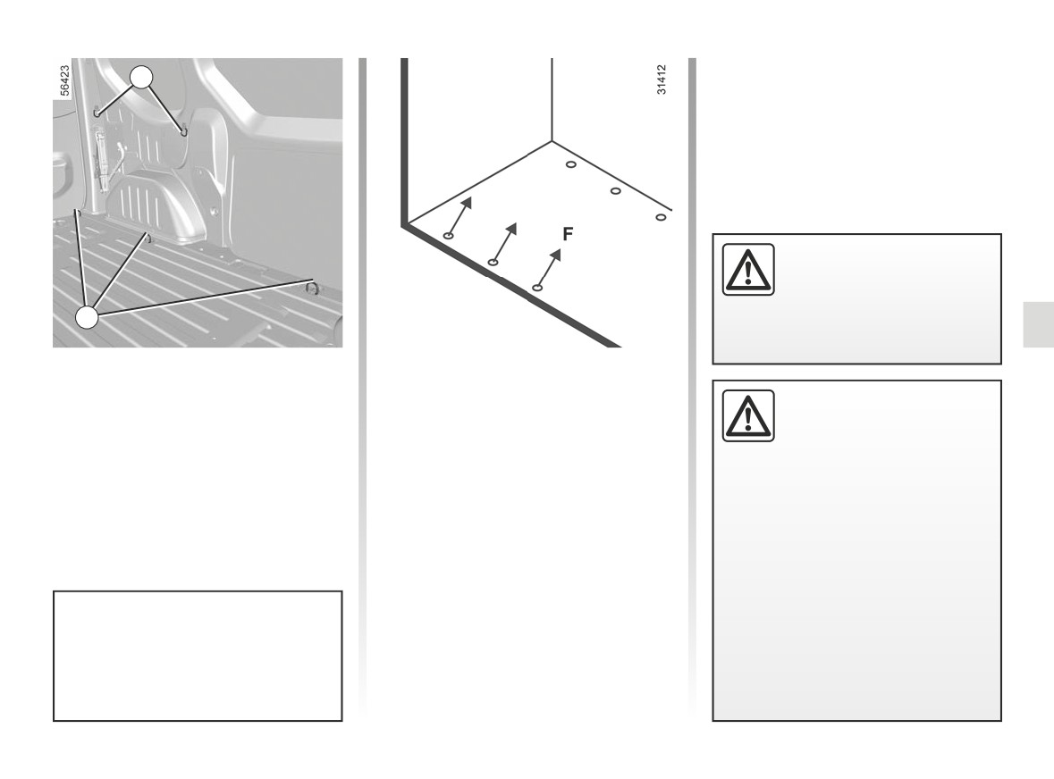
1
For your safety, check that
all the vehicle’s doors are
properly closed before
starting the engine.
2
Transporting objects in the
Special note for van version
rear load area
Rotary rings 2:
While driving with the right
Depending on the vehicle, fixed rings 1
F max: 400 daN
rear hinged door open,
and rotary rings 2 are used to retain ob-
always secure transported
jects in transit. The number of rings and
loads. The left-hand door,
their position may vary depending on
which remains shut, should not be
the vehicle.
used to hold transported loads in
place. Using the right rear hinged
door open while driving should only
be done in exceptional cases.
In any event, please refer to local
legislation. Risk of loads falling on
the road surface.
The sole purpose of these rings 1 is
to prevent transported objects from
moving. The objects must be se-
cured to the mounting rings 2 on the
vehicle floor beforehand.
3.29
CarManuals2.co
TRANSPORTING OBJECTS towing, attachments
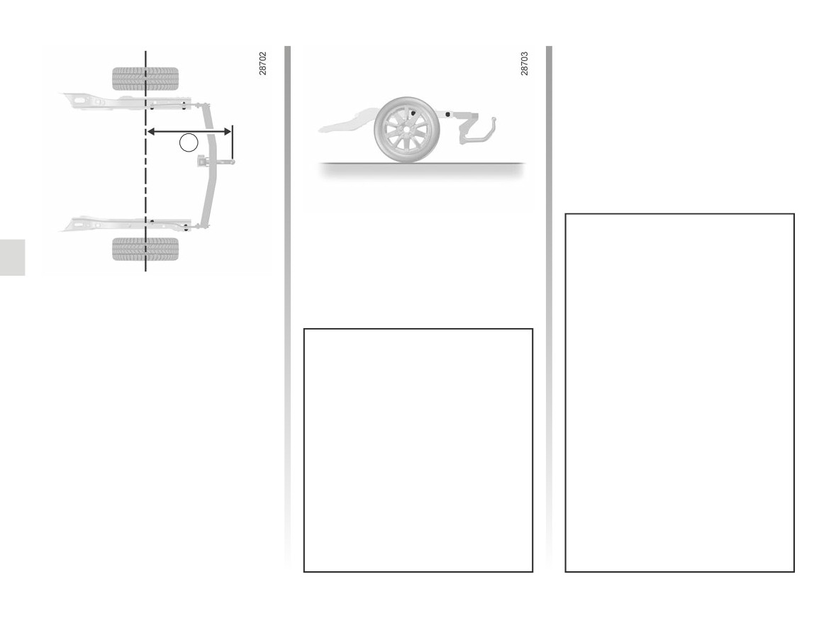
A
Permissible nose weight, maxi-
mum permissible towing weight
braked and unbraked ➥ 6.9.
Maximum dimension A = 855 mm.
Choice and fitting of towing
equipment
Maximum weight of towing equip-
ment: 20 kg.
It is not permitted to fit a mechanical
Any towing device must not ob-
towing device (ball, hook, etc.) that
struct any lighting component or
is removable without tools or retract-
the number plate when not in use.
able if it cannot be easily removed
Mechanical towing devices (ball,
or repositioned when not in use.
hook, etc.) which can be removed
without tools and retractable objects
For information on how to fit the
must be removed or repositioned
towing equipment and the condi-
when they are not in use.
tions of use, refer to the fitting in-
structions.
In all cases, you must comply with
Please keep these instructions with
the regulations of the particular
the rest of the vehicle documenta-
country you are in.
tion.
3.30
CarManuals2.co
TRANSPORTING OBJECTS Luggage net
2
1
2
1
4
7
8
9
5
6
3
10
3
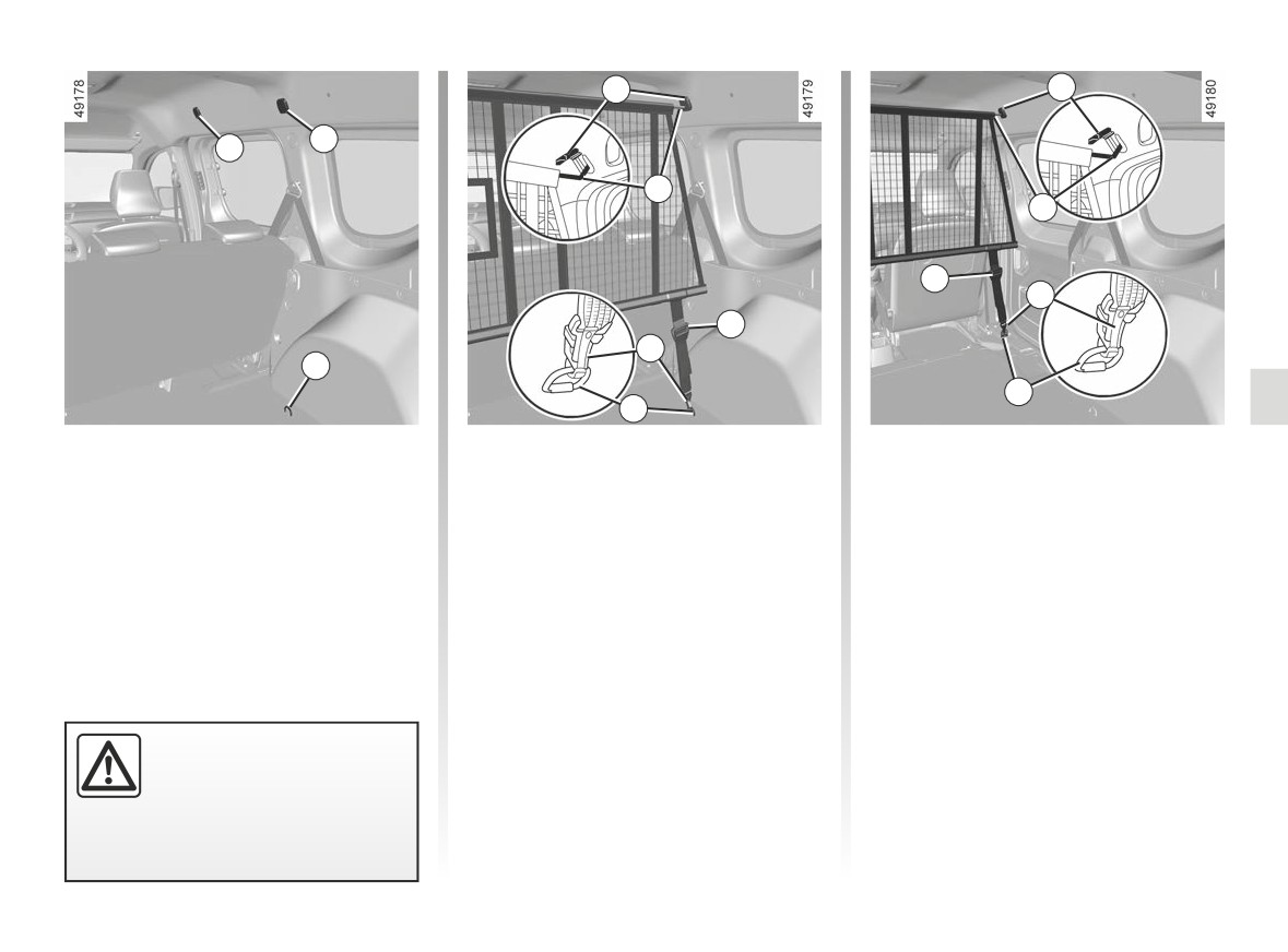
On equipped vehicles, the luggage net
Fitting the luggage net
Fitting the luggage net
can be used, when transporting ani-
behind the rear seats
behind the front seats
mals or luggage, to separate them from
the passenger section.
Inside the vehicle on each side:
Inside the vehicle on each side:
It is fitted behind the rear bench seat or
- lower cover 2 to gain access to the
- lower cover 1 to gain access to the
behind the driver and passenger seats.
anchoring points for the top part of
anchoring points for the top part of
the luggage net;
the luggage net;
- insert the top rod of net 4 into the an-
- insert the top rod of net 7 into the an-
choring points;
choring points;
- attach the two hooks 6 of the straps 5
- attach the two hooks 9 of the straps 8
from the net onto the anchoring
from the net onto the anchoring
points 3;
points 10;
The luggage net must not
– adjust the net strap 5 so that it is taut.
- adjust the net strap 8 so that it is taut.
be used to restrain or hold
objects.
Risk of injury.
3.31
CarManuals2.co
LUGGAGE COVER
A
B
1
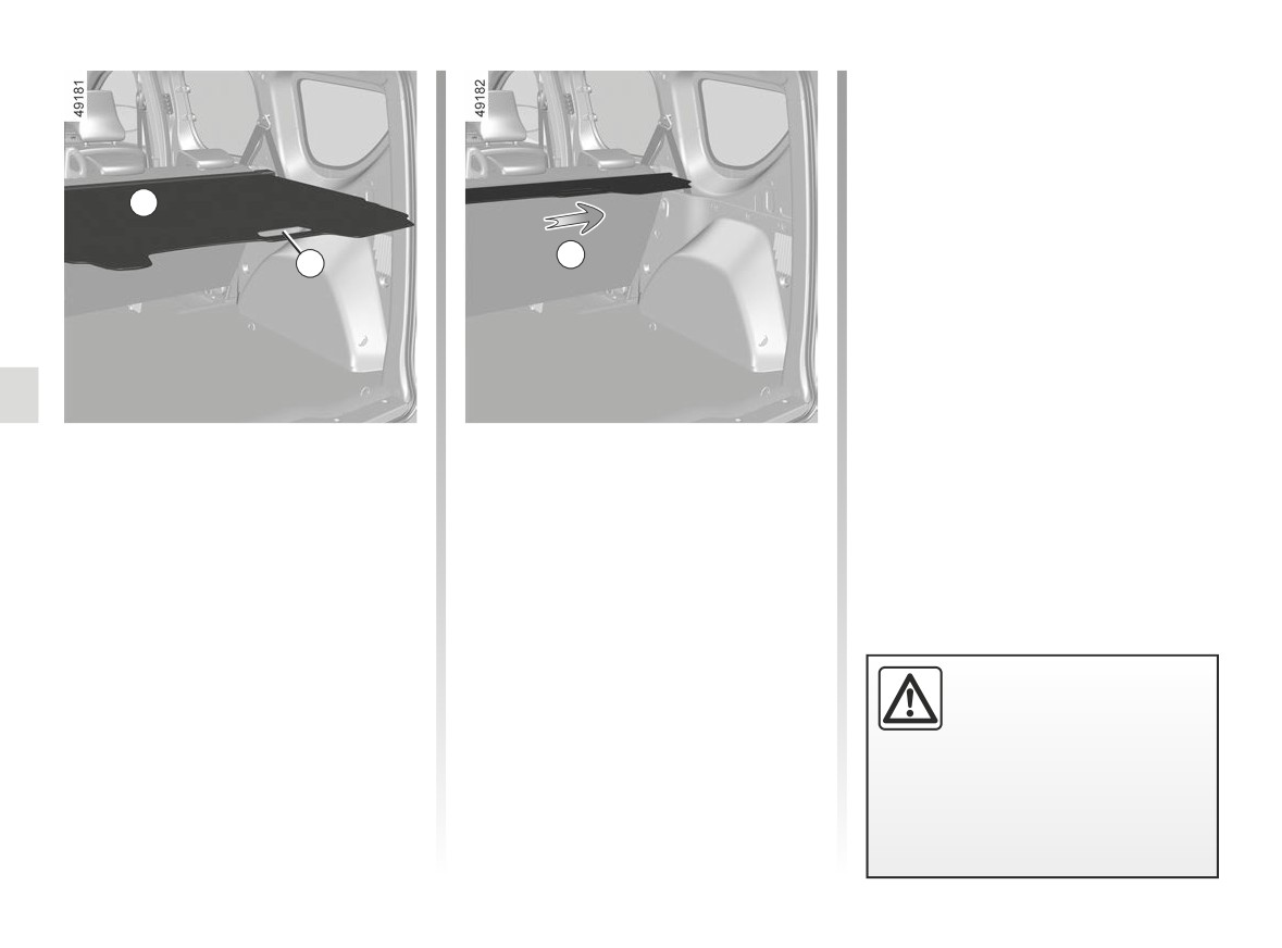
How to remove the luggage
Removing the luggage
compartment cover A
compartment cover
Using handle 1, pull it gently to release
Push the luggage cover to the right
the pins from their mounting points, lo-
(movement B) and lift the left-hand side
cated on each side of the luggage com-
of the inertia reel.
partment.
Guide the luggage cover using the
Refitting the luggage
handle 1.
compartment cover
Insert the right-hand side, then push it
Do not place any heavy or
to the right and lower the left-hand side
hard objects on the luggage
of the inertia reel into its housing.
cover. These may pose a
risk to the vehicle occu-
pants if the driver has to brake sud-
denly or if the vehicle is involved in
an accident.
3.32
CarManuals2.co
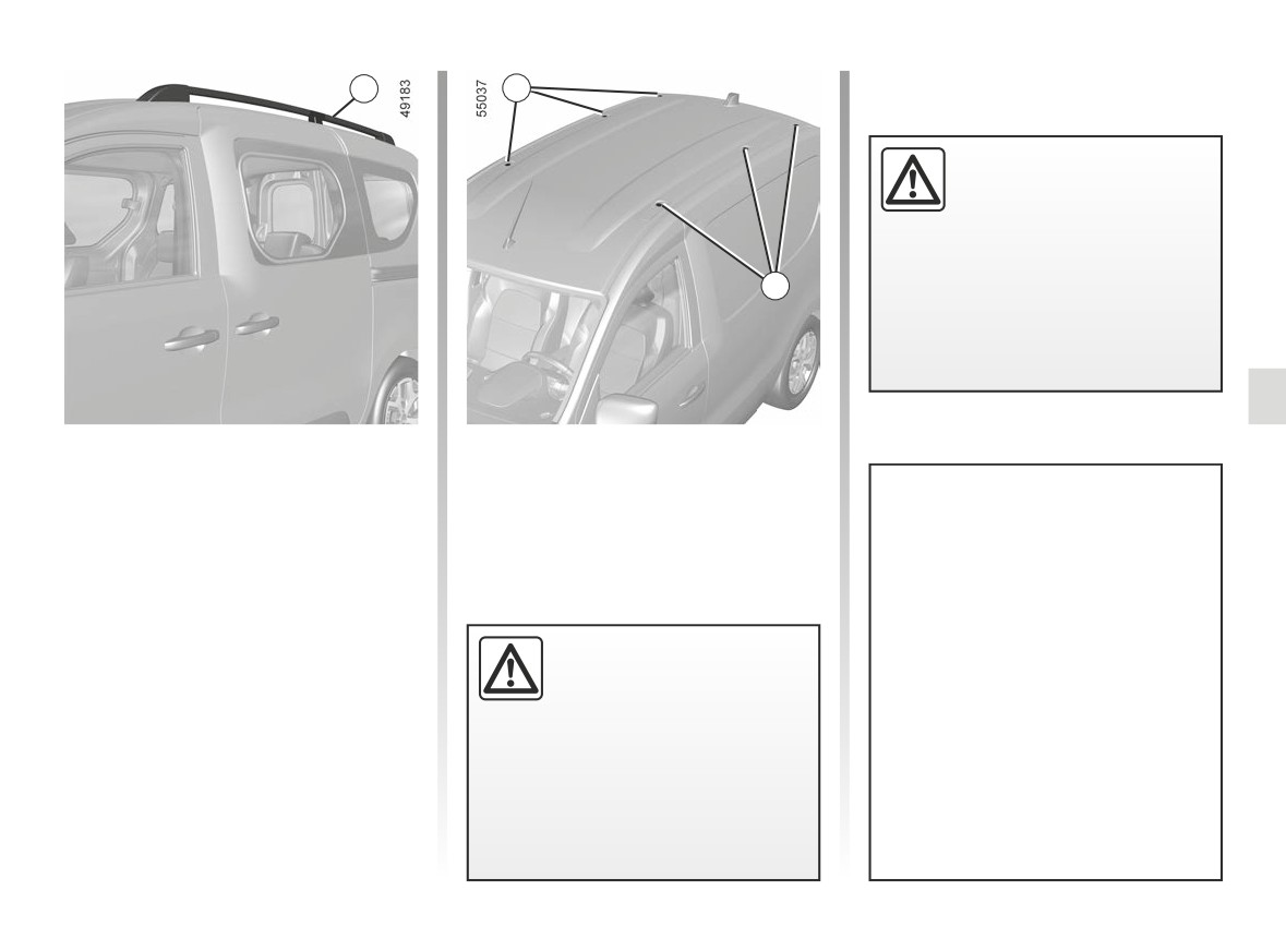
ROOF BARS
1
2
The attaching of any carry-
ing device (bike rack, lug-
gage box, etc.) resting on
the luggage compartment
lid is prohibited. To install a carrying
device on your vehicle, contact an
2
Approved Dealer.
Vehicles fitted with
Vehicles not fitted with
longitudinal roof bars
longitudinal roof bars
If fitted on the vehicle, you can trans-
Unscrew the blanking covers 2 in order
port luggage or additional equipment
to access the mounting points.
For information on the range of
(bike racks, ski racks, etc):
equipment adapted to your vehi-
- on a roof rack;
cle, we advise you to consult an ap-
- on transverse roof bars fitted onto
proved Dealer.
the longitudinal roof bars 1;
Refer to the manufacturer’s instruc-
- directly onto the longitudinal roof
If original roof bars, ap-
tions for information on how to fit
bars.
proved by our Technical
and use the roof rack bars.
It is forbidden to fit longitudinal roof
Department, are supplied
with screws, only use these
Please keep these instructions with
bars on vehicles which are not origi-
screws for attaching the roof bars to
the rest of the vehicle documenta-
nally equipped with them.
the vehicle.
tion.
Maximum permissible load on
roof rack ➥ 6.9.
3.33
CarManuals2.co
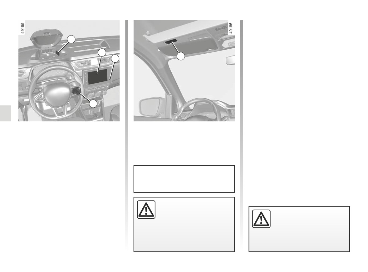
MULTIMEDIA EQUIPMENT (1/2)
Sockets USB 1
The sockets USB can only allow re-
1
charge accessories approved by the
brand's Technical Services of power
2
not exceeding 12 watts (voltage 5 V)
5
3
per outlet.
Multimedia socket 3
You can use USB socket to access the
multimedia content of your accessories.
The various sources can be selected
4
from the multimedia screen and from
the steering column controls.
The location and operation of equip-
ment may vary according to the vehicle.
1 USB sockets;
2 Multimedia screen;
3 Multimedia socket;
4 Steering column controls;
5 Microphone.
Please refer to the multimedia in-
structions for further information.
Hands-free telephone
integrated control
On equipped vehicles, use the hands-
Using the telephone
free telephone controls 4 under the
We remind you of the need
Connect accessories with a
steering wheel.
to conform to the legislation
maximum power of 12 watts
in force concerning the use
only.
of such equipment.
Fire hazard.
3.34
CarManuals2.co
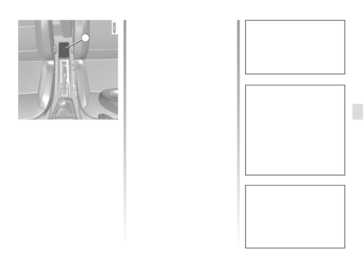
MULTIMEDIA EQUIPMENT (2/2)
Charging procedure
Place your telephone at the centre of
6
the induction area 6.
With the engine running, check that
the warning light turns orange when
Phone charging is interrupted in the fol-
the telephone is positioned in the in-
lowing cases:
duction charging area 6.
- an object is detected in the induction
area 6;
- the induction area 6 is overheating.
Once the temperature has dropped,
your telephone will soon start to
charge again.
It is essential not to leave any ob-
jects (USB drive, SD card, credit
Charging progress
card, jewellery, keys, coins etc.) in
Wireless charger - induction
The charger indicator shows the phone
the induction charging area 6 whilst
charging status:
charging your phone. Remove all
charging
magnetic cards or credit cards from
-
green: charging complete;
Use the induction charging zone 6 to
the case before positioning your
charge a telephone without a cable.
–
orange: charging in progress;
telephone in the induction charging
Note:
–
flashing orange: charging
inter-
area 6.
rupted.
- for more information on the list of
compatible telephones, contact an
authorised dealer or the telephone
manufacturer;
- it is preferable to remove the protec-
tive bodyshell or case from your tele-
Objects left in the induction charging
phone before charging to obtain op-
area 6 may overheat. It is advisable
timal charging.
to place them in the other storage
areas provided. (storage compart-
ment, sun visor storage compart-
ment, etc.)
3.35
CarManuals2.co
3.36
CarManuals2.co
Section 4: Maintenance
Bonnet
4.2
Engine oil level: general information
4.4
Engine oil level: topping up, filling and oil change
4.6
Levels
4.9
Filters
4.11
Battery
4.12
Tyre pressure
4.14
Bodywork maintenance
4.16
Interior trim maintenance
4.19
4.1
CarManuals2.co
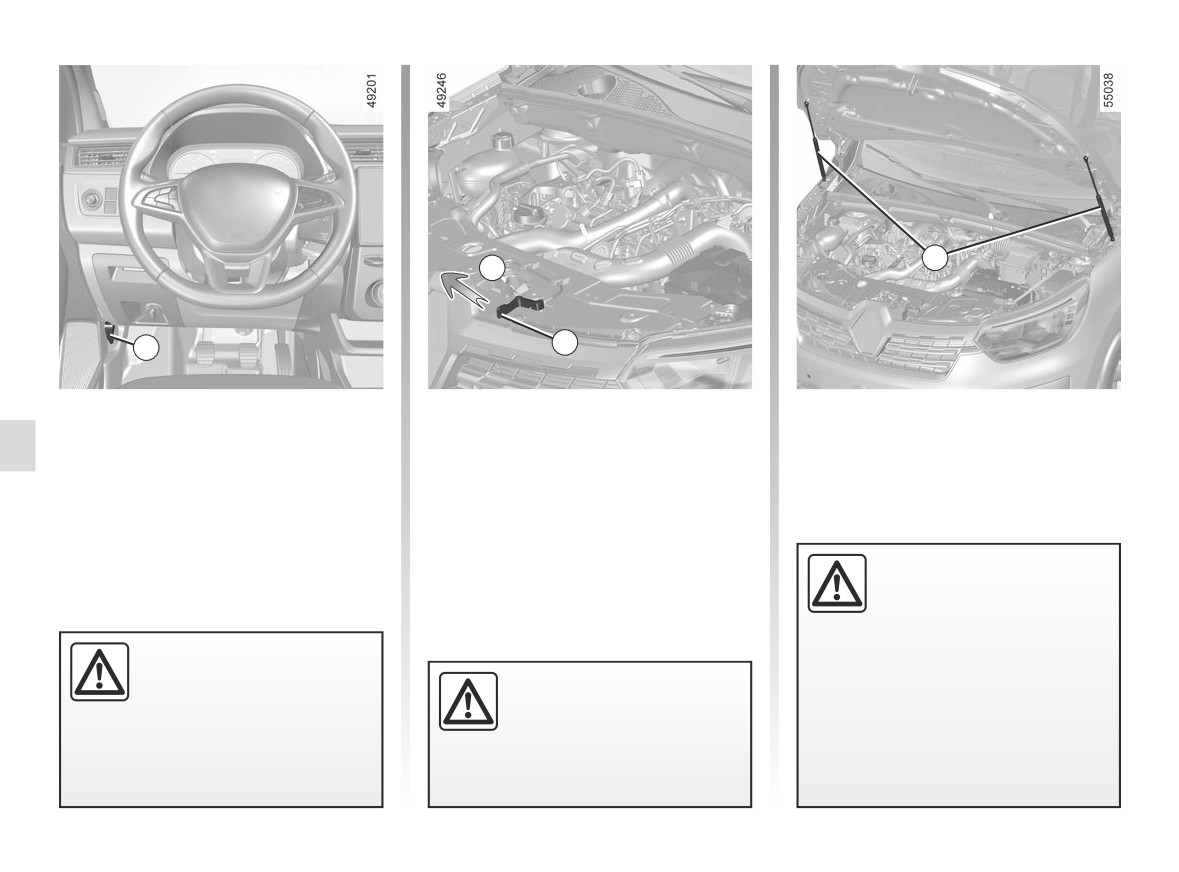
BONNET (1/2)
3
A
2
1
To open the bonnet, open a door and
Opening the bonnet
pull the 1 handle, located on the left-
To unlock, gently lift the bonnet and
hand side of the dashboard.
push tab 2 in the direction of arrow A to
release the bonnet.
Lift the bonnet, guiding it up, and it
will rest in position with the help of two
struts 3.
Please note when work-
ing close to the engine that
it may be hot. The engine
cooling fan may also start
Before carrying out any
at any moment. The y
label in
action in the engine com-
Ensure that the bonnet is
the engine compartment reminds
partment, you must switch
properly locked.
you of this.
off the ignition. ➥ 2.3.
Ensure that nothing is pre-
Risk of injury.
venting locking (grit, cloths,
etc.).
4.2
CarManuals2.co
BONNET (2/2)
Closing the bonnet
Check that nothing has been left in the
engine compartment.
To close it again, hold the bonnet in the
middle and lower it to 25 cm above the
closed position, then release it. Ensure
that the bonnet is properly closed.
If it does not lock itself under its own
weight, gently push it until it fully locks.
When working in the engine
compartment, ensure that
the windscreen wiper stalk
is in the park position.
Risk of injury.
Make sure nothing is left
in the engine compartment
In the event of even a slight
(cloth, tools, etc.).
impact involving the radi-
These may damage the
ator grille or bonnet, have
engine or cause a fire.
the bonnet lock checked by
an approved Dealer as soon as pos-
sible.
4.3
CarManuals2.co
ENGINE OIL LEVEL: general information (1/2)
It is normal for an engine to use oil for
lubrication and cooling of moving parts
and it is normal to top up the level be-
tween oil changes.
However, contact your approved
Dealer if more than 0.5 litres is being
consumed every 600 miles (1,000 km)
after the running in period.
Oil change frequency: check the oil
level from time to time and certainly
before any long journey to avoid the
risk of damaging your engine.
Ensure that the bonnet is
properly locked.
Check that nothing is pre-
venting the catch from lock-
ing (gravel, cloth, etc.).
Adding engine oil
Use a funnel or protect the
filling neck area to avoid
engine oil escaping onto a
hot part of the engine compartment
or a sensitive part (e.g. electrical
components).
Before carrying out any
action in the engine com-
Fire hazard.
partment, you must switch
off the ignition. ➥ 2.3.
4.4
CarManuals2.co
ENGINE OIL LEVEL: general information (2/2)
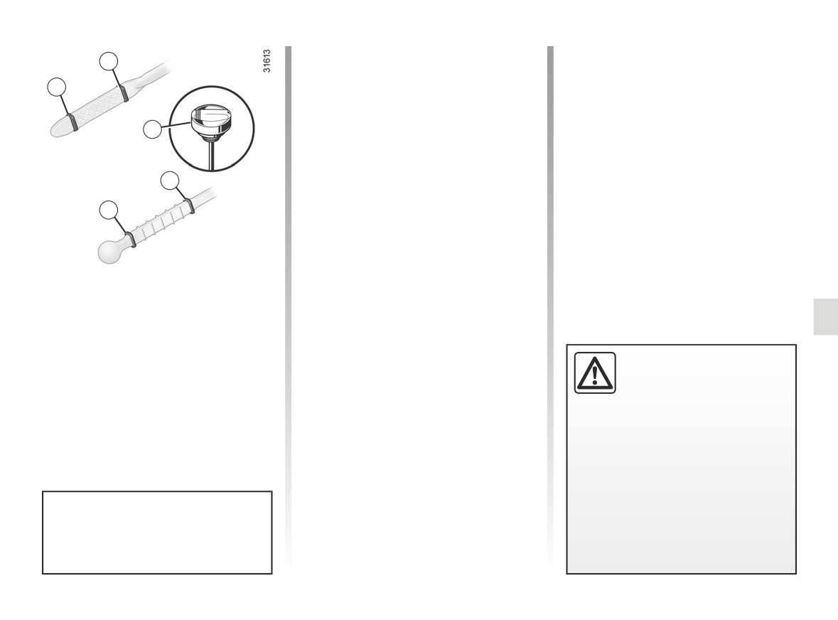
The dipstick must be used to read
B
the exact oil level and make sure that
the maximum level has not been ex-
A
ceeded (risk of engine damage).
Depending on the vehicle, the instru-
C
ment panel display only alerts the driver
when the oil level is at its minimum:
- remove the dipstick and wipe with a
B
clean, lint-free cloth;
- push the dipstick in as far as it will
A
go (for vehicles equipped with a cap-
type dipstick C, screw the cap in as
far as it will go);
- take out the dipstick again;
Reading the oil level
- read the level: it should never fall
The oil level should be read with the ve-
below minimum mark A or exceed
hicle on level ground, after the engine
maximum mark B.
has been switched off for some time.
Once the operation has been com-
pleted, ensure that the dipstick is
Exceeding the maximum
pushed in as far as it will go or that
engine oil level
the “cap-type dipstick” is completely
Under no circumstances
screwed in.
should maximum filling
level B be exceeded: this could
damage the engine and the anti-pol-
lution system.
If the oil level exceeds the maximum
level, do not start your vehicle and
contact an approved Dealer.
Consult your approved dealer at
once if you notice an abnormal or
repeated drop in any of the fluid
levels.
4.5
CarManuals2.co
ENGINE OIL LEVEL: topping up, filling, oil change (1/3)
1
1
1
2
2
1
2
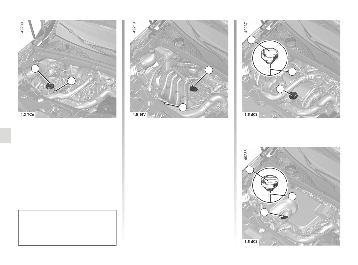
Topping up/Filling
- Unscrew cap 1;
The vehicle must be parked on level
- top up the level (as a guide, the ca-
ground and the engine should be cold
pacity between the minimum and
(for instance, before the engine is
maximum reading on the dipstick 2
started up for the first time in the day).
is between 1.5 and 2 litres, depend-
ing on the engine);
- wait for approximately 20 minutes to
Engine oil grade
1
allow the oil to flow into the engine;
Refer to the Maintenance Document for
- check the level using the dipstick 2
your vehicle.
(as described above).
Once the operation has been com-
2
pleted, ensure that the dipstick is
pushed in as far as it will go or that
1
the “cap-type dipstick” is completely
Do not exceed the “max” level and
screwed in.
do not forget to refit cap 1 and dip-
stick 2.
4.6
CarManuals2.co
ENGINE OIL LEVEL: topping up, filling, oil change (2/3)
Exceeding the maximum
engine oil level
Under no circumstances
should the maximum fill-
ing level be exceeded: this could
damage the engine and the emis-
sion control system.
If the oil level exceeds the maximum
level, do not start your vehicle and
Never run the engine in an
contact an approved Dealer.
enclosed space as exhaust
gases are poisonous.
Before carrying out any
action in the engine com-
partment, you must switch
off the ignition. ➥ 2.3.
Adding engine oil
Use a funnel or protect the
Please note when work-
filling neck area to avoid
ing close to the engine that
engine oil escaping onto a
it may be hot. In addition,
hot part of the engine compartment
the engine cooling fan may
or a sensitive part (e.g. electrical
When working in the engine
come on at any moment. The y
components).
compartment, ensure that
warning light in the engine compart-
Fire hazard.
the windscreen wiper stalk
ment reminds you of this.
is in the park position.
Risk of injury.
Risk of injury.
4.7
CarManuals2.co
ENGINE OIL LEVEL: topping up, filling, oil change (3/3)
Oil change
Service interval: refer to the
Consult an approved dealer at once
Maintenance Document for your vehi-
if you notice an abnormal or re-
cle.
peated drop in any of the fluid levels.
Oil change capacity
Please refer to the maintenance docu-
Engine oil change: if you
ment for your vehicle, or contact an au-
are changing the oil when
thorised dealer.
the engine is hot, be careful
not to scald yourself if the
Always check the engine oil level using
oil overflows.
the dipstick, as explained previously (it
should never fall below the minimum
level, or be over the maximum level on
the dipstick).
Filling and/or checking
the oil level: when topping
up or checking the oil level,
ensure that no oil leaks onto
Exceeding the maximum
the engine components.
engine oil level
Do not forget to properly close the
Under no circumstances
cap and refit the dipstick to prevent
should the maximum fill-
any oil spatter on hot engine com-
ing level be exceeded: this could
ponents.
damage the engine and the emis-
Fire hazard.
sion control system.
If the oil level exceeds the maximum
level, do not start your vehicle and
contact an approved Dealer.
4.8
CarManuals2.co