Renault Express (2023 year). Manual in english - page 3
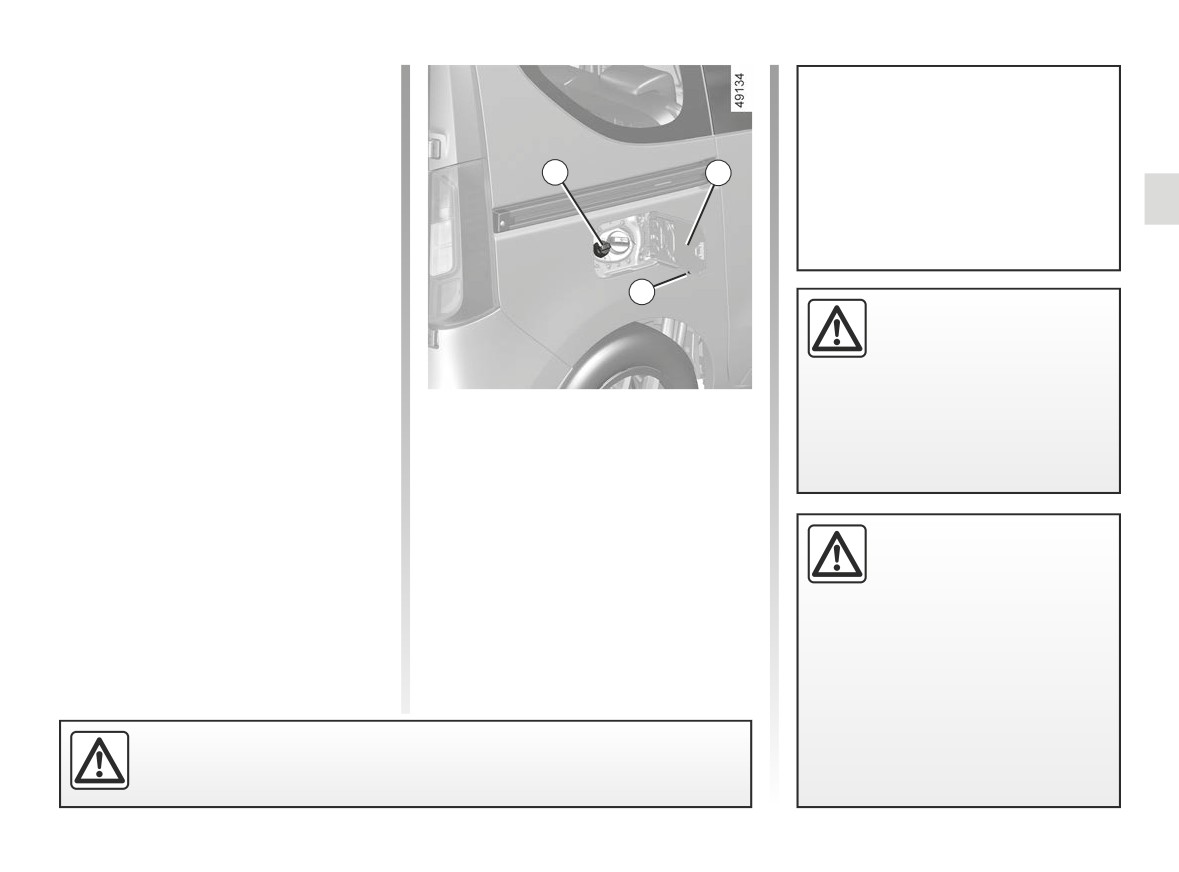
REAGENT TANK (1/4)
Always comply with the legislation in
place in the country where you are lo-
cated. Not abiding by the regulations in
To fill up with reagent, the engine
force may expose the vehicle owner to
must be stopped
(not just on
prosecution.
1
A
standby in the case of vehicles with
the STOP and START function). You
Operating principle
must switch off the ignition ➥ 2.3.
The reagent is intended for diesel en-
gines fitted with the SCR (selective cat-
alytic reduction) system.
Using a reagent reduces the quantity of
2
If the “xxxKM failure Top up
nitrogen oxides in exhaust gases.
AdBlue” message appears,
Reagent consumption in real time de-
fill the reagent tank and
pends on vehicle usage conditions, the
refer to the filling instruc-
equipment fitted, and driving style.
tions.
Filling
Risk of immobilisation of the
Reagent quality
Capacity of the tank: 17 litres approx-
vehicle.
Use only reagents which conform
imately.
to standard ISO 22241 and in accord-
With the ignition switched off, open the
ance with the mark on the tank filler
cover A, then unscrew the cap 1.
cap.
Cap holder 2 is provided on the fuel
filler flap for holding the cap when the
Filler cap: this is specific.
tank is being filled.
If you have to replace it,
Note: ammonium hydroxide vapour
make sure it is identical to
may escape from the cap opening
the original cap. Contact
when the tank temperature is high.
an approved Dealer. Do not wash
the filler area with a high pressure
washer.
The reagent must not come into contact with eyes or skin. If it does, wash
the affected area with plenty of cold water. If necessary, consult a doctor.
1.99
CarManuals2.co
REAGENT TANK (2/4)
Filling (continued)
If the reagent overflows, or contami-
nates any paintwork, clean the affected
The tank can be filled at the pump. With
area quickly with plenty of cold water
the ignition off, insert the nozzle and
and a soft cloth.
insert it fully before turning it on to fill
the fuel tank (risk of splashing).
Note: If the reagent crystallises, use a
After filling the reagent tank, check
soft sponge.
that the cap and cover are closed,
No more than two filling operations may
start the engine and WAIT 10 sec-
be made after the feed has switched off
In extreme cold weather conditions
onds with the vehicle stationary,
automatically for the first time because
In frosty weather conditions, the rea-
engine running before setting off
there must be room for expansion in the
gent tank should be refilled when the
again.
tank.
If this operation is not carried out,
indicator and the message “Top
In other filling cases, it is essential to
the filling of the tank will not be
Up AdBlue before 1200 km” appear on
read the information shown on the re-
taken into account automatically
the instrument panel.
agent container (e.g. the can or bottle).
until after several dozens of minutes
Special cases
of driving.
The message “--- TOP UP AdBlue”
Precautions for use
The reagent fluid freezes below about
and/or the warning lights will con-
-10°C.
When filling:
tinue to appear until the filling has
In these conditions, do not attempt fill-
been taken into account by the
- handle the reagent with care. They
ing when the fluid is frozen. In the event
system.
can damage clothes, shoes, body-
of needing to top up or fill the tank with
work components etc. ;
reagent (
on), park the vehicle
- make sure that no water enters the
in a hotter location if possible so that
fuel tank.
the reagent becomes liquid again.
Otherwise, have a qualified profes-
sional top up or fill up with reagent fluid.
No work whatsoever is
permitted on any part of
the system. To prevent
damage, only qualified per-
sonnel from our network may work
on the system.
1.100
CarManuals2.co

REAGENT TANK (3/4)
Maintenance/Range
The information displayed on the instrument panel may be accompanied by a beep.
Indicator lights
Message
What to do?
When the message is displayed when the ignition is switched on, you have less
“Top Up AdBlue
-
than 1,488 miles (2,400 km) range.
before 2400 km”
Fill or have an Approved Dealer fill or top up the reagent in the tank.
When the message is displayed when the ignition is switched on, you have be-
“TOP UP AdBlue
tween 744 miles (1,200 km) and 496 miles (800 km) range.
comes on.
before 1200 km”
Fill or have an Approved Dealer fill or top up the reagent in the tank.
The message is displayed when the ignition is switched on and is repeated:
- approximately every 62 miles (100 km), you have between about 496 miles
(800 km) and 124 miles (200 km) range;
“xxxKM failure Top
- approximately every 31 miles (50 km), you have less than 124 miles
comes on.
up AdBlue”
(200 km) range.
In any event, fill or have an Approved Dealer fill the reagent tank as soon as
possible.
«
0KM FAILURE
The engine will not start.
flashes.
TOP UP ADBLUE »
To restart, you must fill the reagent tank yourself.
1.101
CarManuals2.co

REAGENT TANK (4/4)
System faults
The information displayed on the instrument panel may be accompanied by a beep.
Indicator lights
Message
Readings
“CHECK ANTI- POLLUTION SYSTEM”
Indicates a fault in the system. Contact your approved
and
come
“AdBlue quality to check”
dealer as soon as possible.
on.
“AdBlue injection to check”
Indicates a system fault and that in less than
496 miles (800 km) it will become impossible to
restart the vehicle.
These warnings are repeated:
- every 62 miles (100 km) until there are between
“xxx MILES (xxx KM) failure antipollu-
and
come
500 miles (800 km) and 124 miles (200 km) re-
tion”
on.
maining until the vehicle cannot be restarted;
- every 31 miles (50 km) when there is less than
124 miles (200 km) left before the vehicle cannot
be restarted.
Contact your approved dealer as soon as possible.
Indicates that after the ignition is switched off the vehi-
and
come
“0KM FAILURE TOP UP ADBLUE”
cle will not restart. Call an approved Dealer.
on.
1.102
CarManuals2.co
Section 2: Driving
(Advice on use relating to fuel economy and the environment)
Running in
2.2
Ignition switch
2.2
Starting, stopping the engine
2.3
Stop and Start function
2.5
Special feature of petrol versions, particle filter
2.8
Special features of diesel versions, particle filter
2.10
Driving advice, Eco-driving
2.12
Maintenance and antipollution advice
2.16
Environment
2.17
Tyre pressure monitoring system
2.18
Gear lever, handbrake
2.21
Rear camera
2.22
Driver correction devices and aids
2.25
Speed limiter
2.30
Cruise control
2.33
Parking distance control
2.37
Reversing camera
2.42
Blind spot warning
2.45
Overspeed function
2.49
Emergency call
2.50
2.1
CarManuals2.co
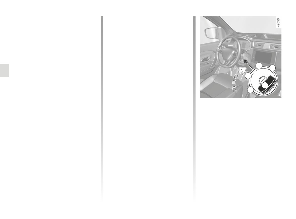
RUNNING IN, IGNITION SWITCH
Petrol version
Note: for a new vehicle in the running-in
phase: the coolant level may be higher
For the first 600 miles (1,000 km), do
than the “MAXI” mark on the tank, then
not exceed 80 mph (130 km/h) in the
drop to between the “MINI” and “MAXI”
highest gear, or 3,000 to 3,500 rpm.
marks.
You may only expect top performance
This does not present a risk.
from your vehicle after approximately
1,800 miles (3,000 km).
Off position A (steering lock
Service intervals: refer to the
Maintenance Service Booklet for the
applied)
C
D
vehicle.
To lock: remove the key 1 and turn the
B
steering wheel until the steering column
locks.
Diesel version
1
A
To unlock: turn the key and the steering
For the first 1,000 miles (1,500 km),
wheel slightly.
do not exceed 80 mph (130 km/h) in
“Start” position D
the highest gear, or 2,500 rpm. After
completing this mileage you may drive
“Accessories” position B
If the engine fails to start at the first
faster, although you may only expect
attempt, the key must be turned back
When the ignition is switched off, any
top performance after approximately
before the starter can be activated
accessories (radio, etc.) will continue to
3,600 miles (6,000 km).
again.
function.
During the running in period, do not ac-
Release the key as soon as the engine
celerate hard while the engine is still
starts.
cold and do not let the engine over-rev.
“Ignition” position C
Note: on diesel versions, several sec-
Service intervals: refer to the
The ignition is switched on:
onds may pass between turning the
Maintenance Document for your vehi-
key and the engine starting to allow for
- Petrol version: the engine may be
cle.
engine preheating.
started.
- Diesel version: the engine is pre-
heating.
2.2
CarManuals2.co
STARTING, STOPPING THE ENGINE (1/2)
Starting the engine
Petrol version
Depending on the vehicle, if a gear is
- Turn the key to the start position
engaged, for the engine to be started,
without depressing the accelera-
you must depress the clutch pedal or
tor.
put the gear lever in neutral.
- Release the key as soon as the
In very cold conditions (temperatures
engine starts.
below -20°C): so that it is easier to
Diesel version
start the engine, switch on the ignition
É
for several seconds before starting the
– Turn the ignition key to the “On” po-
engine.
Never start your vehicle
sition and keep it turned until the
while freewheeling on a
When starting the engine, if the outdoor
engine preheating light goes off;
gradient. Risk of non-ac-
temperature is very low (below -10°C):
- turn the key to the start position
tivation of power-assisted
hold down the clutch pedal until the
without pressing the accelerator;
steering.
engine starts.
- release the key as soon as the
engine starts.
There is a risk of accidents.
Do not park the vehicle or
run the engine in locations
where combustible sub-
stances or materials such
as grass or leaves can come into
contact with the hot exhaust system.
Fire hazard.
2.3
CarManuals2.co
STARTING, STOPPING THE ENGINE (2/2)
Stopping the engine
With the engine idling, turn the key
back to the “Stop” position.
Driver’s responsibility
when parking or stopping
Special note
the
vehicle
Depending on the vehicle, accessories
Never leave an animal, child or adult
(e.g. radio) stop working either when
who is not self-sufficient alone on
the engine is switched off or when the
your vehicle, even for a short time.
doors are locked, or when the driver’s
They may pose a risk to themselves
door is opened.
or to others by starting the engine,
activating equipment such as the
electric windows or locking the
doors, for example.
Also, in hot and/or sunny weather,
please remember that the tempera-
ture inside the passenger compart-
ment increases very quickly.
RISK OF DEATH OR SERIOUS
INJURY.
Never switch off the igni-
tion before the vehicle has
stopped completely. Once
the engine has stopped, the
brake servo, power-assisted steer-
ing etc., and the passive safety de-
vices such as the airbags and pre-
tensioners will no longer operate.
2.4
CarManuals2.co
STOP AND START function (1/3)
This system enables a reduced fuel
For all vehicles:
consumption and lower greenhouse
gas emissions.
The warning light
on the instru-
The system is activated automatically
ment panel is lit when the engine is on
when the vehicle is started.
standby.
While driving, the system stops the
The vehicle equipment remain opera-
engine (standby) when the vehicle is
tional while the engine is stopped.
at a standstill (traffic jam, traffic lights,
etc).
When the engine switches to standby,
the steering assistance may no longer
be operational.
Conditions for engine
In this case it becomes operational
standby
again when the engine is no longer on
The vehicle has set off from where it
standby or the speed exceeds approxi-
If you get out of the vehicle, a beep
was parked;
mately 1 mph (1 km/h) (downhill, slope
notifies you that the engine is on
etc.).
standby and has not been switched
For manual gearboxes:
off.
- the gearbox is in neutral;
and
- the vehicle speed is less than ap-
proximately 7 mph (3 km/h).
The engine
MUST be
and
stopped (not put in standby)
before leaving the vehicle.
- the clutch pedal is released.
➥ 2.3.
If warning light
flashes, this
means that the clutch pedal is not
sufficiently released.
Do not drive off when the
engine is on standby (warn-
If the engine stalls while the system
ing light
is displayed
is in operation, pressing the clutch
on the instrument panel).
pedal right down will start it again.
2.5
CarManuals2.co
STOP AND START function (2/3)
Preventing the engine from
Conditions for coming out of
Conditions preventing the
standing by
engine standby
standby of the engine
In certain situations, such as negoti-
For manual gearboxes:
Certain conditions prevent the system
ating a crossroads for instance, it is
from using the engine standby function,
- when opening the driver’s door, with-
possible (with the system activated) to
including when:
out any gear engaged and the clutch
keep the engine running so as to be
pedal released;
-
the driver’s door is not closed;
ready to move off quickly.
or
–
the driver’s seatbelt is not fastened;
Manual gearbox
- when unfastening the driver’s seat
–
reverse gear is engaged;
Keep the clutch pedal pressed right
belt, without any gear engaged and
down.
the clutch pedal released;
–
the bonnet is not locked;
or
–
the outdoor temperature is too low or
- the gearbox is in neutral and the
too high;
clutch pedal is slightly depressed;
-
the battery is not sufficiently charged;
or
–
parking distance control is in opera-
- the engine is in gear and the clutch
tion;
For vehicles equipped with a
pedal is pressed right down.
manual gearbox
-
the altitude is too high;
Special note: depending on the vehi-
The restart may be interrupted if the
-
the engine temperature is too low;
cle, if you switch off the ignition when
clutch pedal is released too quickly
the engine is on standby, the warning
–
the emission control system is being
while a gear is engaged.
regenerated;
light Ä
is displayed for a few sec-
onds on the instrument panel.
-
Warning light
is displayed on the
instrument panel. This notifies you that
engine standby is not available.
To fill up with fuel, the engine must
be stopped (and not only on standby
in the case of vehicles equipped with
the STOP and START function): you
Deactivate the Stop and
must switch off the ignition ➥ 2.3.
Start function for any opera-
tion performed in the engine
Fire hazard.
compartment.
2.6
CarManuals2.co
STOP AND START function (3/3)
Special feature of the automatic
The system is automatically reactivated
engine re-start
each time the vehicle is started using
the start button. ➥ 2.3.
Under certain conditions, the engine
can restart on its own in order to guar-
antee your safety and comfort.
Operating faults
This can occur especially when:
When the “Check Stop & Start” mes-
– the outdoor temperature is too low or
sage appears on the instrument panel
too high;
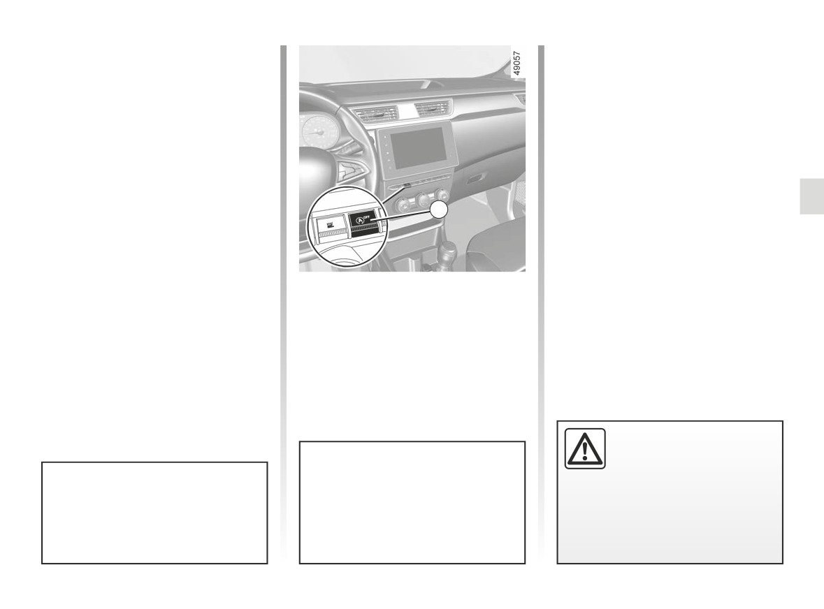
and the 1 switch is on, this indicates
– the battery is not sufficiently charged;
that the system is deactivated.
– the vehicle speed is above 3 mph
Please consult an authorised dealer.
(5 km/h) (downhill slope, etc.);
1
- repeated pressing on the brake
pedal or braking system require-
ment;
- ...
Deactivating, activating the
The
warning light is displayed on
the instrument panel to notify you of au-
function
tomatic engine restarting.
Press 1 to deactivate the function.
The 1 switch warning light illuminates.
Pressing again will reactivate the
system. The 1 switch warning light
goes out.
The engine MUST be
stopped (not put in standby)
before leaving the vehicle.
➥ 2.3.
Special note: depending on the ve-
Special feature: with the engine in
hicle, for some of these conditions
standby, press switch 1 to automati-
automatic restarting of the engine is
cally restart the engine.
inhibited if a door is open.
2.7
CarManuals2.co
SPECIAL FEATURES OF PETROL VERSIONS , PARTICLE FILTER (1/2)
The following operating conditions:
If you notice any of the above operat-
ing faults, have the necessary repairs
- driving for long periods when the low
carried out as soon as possible by an
fuel level warning light is lit;
approved Dealer.
- using leaded petrol;
These faults may be avoided by reg-
- using fuel or lubrication additives
ularly taking your vehicle to your ap-
which are not approved.
proved dealer at the intervals specified
in the maintenance document.
Or operating faults such as:
- faulty ignition system, running out of
fuel or disconnected spark plugs re-
Starting problems
sulting in the engine misfiring or cut-
To avoid damaging the catalytic con-
ting out when driving;
verter or the starter, and to prevent pre-
- loss of power,
mature wearing of the battery, do not
keep trying to start the engine (using
as they may cause the catalytic con-
the start button, or by pushing or towing
verter to overheat and thus reduce its
the vehicle) without having identified
efficiency, or damage it irreparably
and corrected the starting fault.
and cause heat damage to the vehi-
cle.
If the fault cannot be identified, do not
continue to try and start the engine, but
contact an approved dealer.
Do not park the vehicle or
run the engine in locations
where combustible sub-
stances or materials such as
grass or leaves can come into con-
tact with the hot exhaust system.
2.8
CarManuals2.co
SPECIAL FEATURES OF PETROL VERSIONS , PARTICLE FILTER (2/2)
Particle filter
Note: The indicator light may go out
If the filter becomes saturated, the
after 20 minutes when the driving con-
warning light and, depending
The particle filter is used in the treat-
ditions needed to clean the filter are not
ment of exhaust gases from petrol en-
completely met.
on the vehicle, the
warning light
gines.
will appear on the instrument panel,
Depending on the vehicle, the warning
If the vehicle is stopped before the
accompanied by the message “Check
warning light disappears you will have
Vehicle”. In this case, please consult an
light
displayed on the instrument
to restart the process from the begin-
Authorised Dealer.
panel indicates that the filter is becom-
ning.
ing clogged and requires cleaning. To
If the® warning light and, depend-
clean it, when the
warning light
ing on the vehicle, the
warning
appears, and as traffic conditions and
light appears, accompanied by the
speed limits allow, drive at between
“Engine failure hazard” message, stop
about 31 mph (50 km/h) and 68 mph
the vehicle, switch off the engine and
(110 km/h) until the light goes out.
contact an Approved Dealer.
After between approximately 5 and
20 minutes, the warning light should go
out.
Warning light
®
re-
quires you to stop immedi-
ately, for your own safety,
as soon as traffic conditions
allow. Switch off the engine and do
not restart it. Contact an approved
Dealer.
2.9
CarManuals2.co
SPECIAL FEATURES OF DIESEL VERSIONS: PARTICLE FILTER (1/2)
Diesel engine speed
Precautions to be taken in winter
Diesel engines are fitted with an injec-
To avoid any faults in icy weather:
tion pump which prevents the engine
A
-
ensure that the battery is always fully
speed being exceeded irrespective of
charged,
the gear selected.
1
-
always keep the diesel tank rela-
If the message “Check antipollution
tively full to avoid water vapour con-
system” is displayed along with warn-
densing in it and accumulating at the
bottom of the tank.
ing lights Ä
authorised dealer immediately.
When driving, depending on the fuel
grade used, it is possible that white
smoke may be emitted.
This is due to the exhaust particle filter
being cleaned automatically, and does
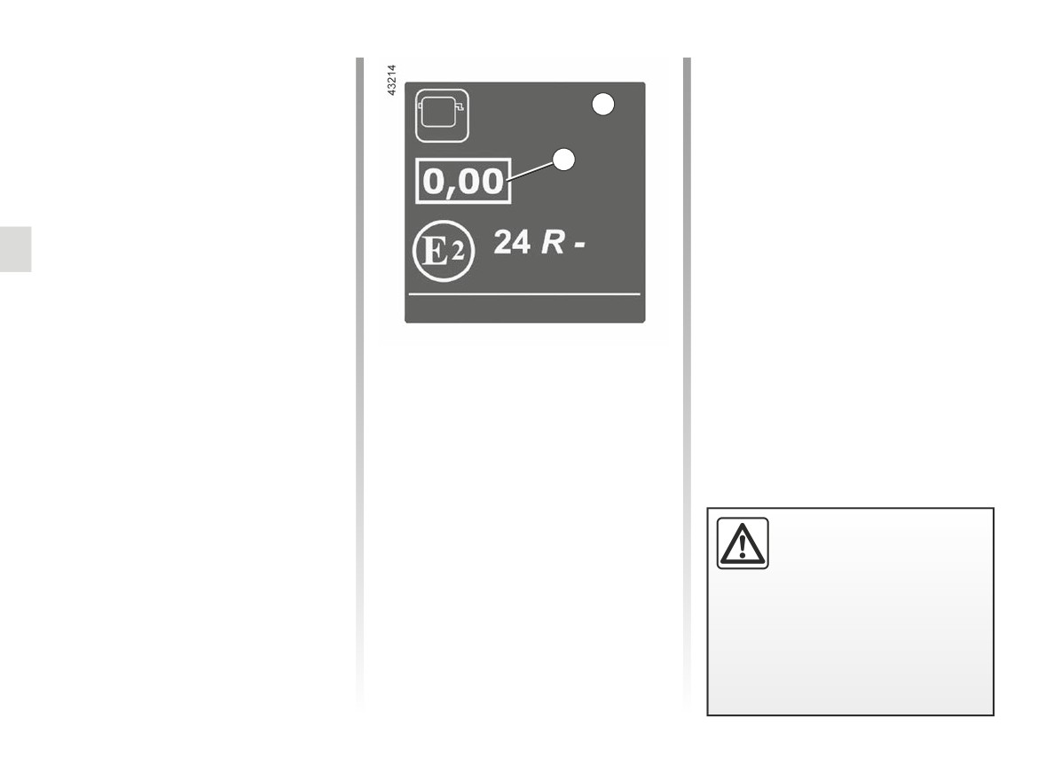
Engine smoke opacity label
not affect the way the vehicle runs.
You can find the information 1 on the
Running out of fuel
label A stuck in the engine compart-
After the tank has been filled following
ment or, depending on the vehicle, on
a complete draining of fuel, the fuel
the vehicle identification plate ➥ 6.2.
system must be reprimed ➥ 1.95 before
1 Diesel exhaust emissions.
restarting the engine.
Do not park the vehicle or
run the engine in locations
where combustible sub-
stances or materials such
as grass or leaves can come into
contact with the hot exhaust system.
2.10
CarManuals2.co
SPECIAL FEATURES OF DIESEL VERSIONS: PARTICLE FILTER (2/2)
Particle filter
Note: the warning light may reappear
If the filter becomes saturated, the
if the driving conditions are not fully
warning light and, depending
The particle filter is used in the treat-
met with regard to cleaning the filter. If
ment of exhaust gases from diesel en-
the vehicle is stopped or if the engine
on the vehicle, the
warning light
gines.
speed drops below 2,000 rpm before
will appear on the instrument panel, ac-
Depending on the vehicle, the warning
the warning light goes out, the opera-
companied by the message “Check in-
tion may need to be repeated.
jection”. In this case, please consult an
light
displayed on the instrument
Authorised Dealer.
panel indicates that the filter is becom-
ing clogged and requires cleaning.
If the
®
warning light and, de-
To do this, when the
warning
pending on the vehicle, the
light is displayed, continue driving ac-
warning light appears, accompanied by
cording to traffic conditions and ob-
the “WARNING: Engine Failure Risk”
serve the speed limit until the warning
message, stop the vehicle, switch off
lights disappears. If possible, do not let
the engine and contact an Approved
the engine speed drop below 2000 rpm.
Dealer.
The warning light should go out after 10
to 20 minutes. ➥ 1.66.
The display of the
on the instru-
ment panel may be accompanied by an
increase in engine speed and operation
of the cooling system in order to clean
the particle filter.
The
®
warning light
requires you to stop imme-
diately, for your own safety,
as soon as traffic conditions
allow. Switch off the engine and
To facilitate the particle filter re-
do not restart it. Call an approved
generation, carry out a long driving
Dealer.
phase (at least 20 minutes) on main
roads every 124 miles (200 km).
2.11
CarManuals2.co
DRIVING ADVICE, ECO DRIVING (1/4)
Fuel consumption is accredited in ac-
cordance with a standard regulatory
method. Identical for all manufactur-
ers, this enables vehicles to be com-
pared with one another. Consumption
in real time depends on vehicle usage
1
conditions, the equipment fitted and the
user’s driving style. To optimise fuel
consumption, please refer to the follow-
1
ing advice.
Depending on the vehicle, you will have
various functions which enable you to
lower your fuel consumption:
- the rev counter;
- gear change indicator;
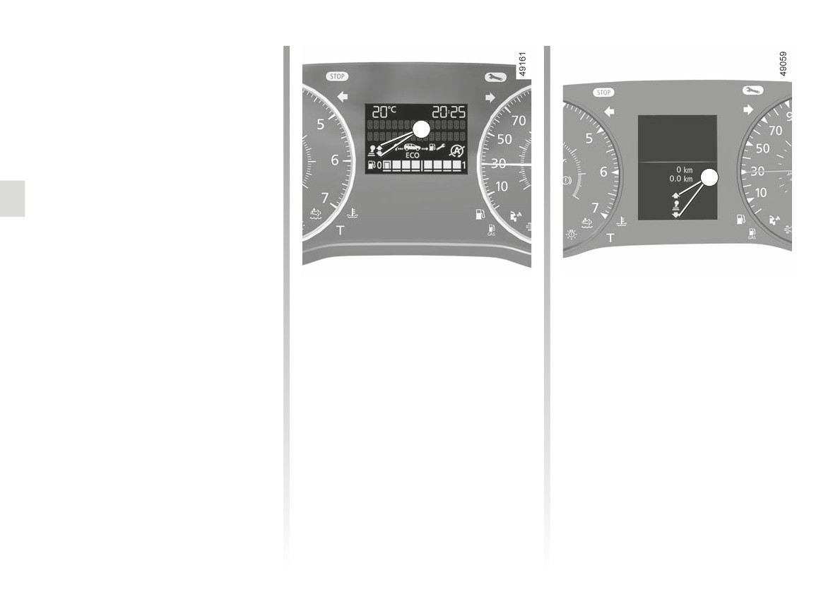
Gear change indicator 1
- ECO mode;
Depending on the vehicle, to obtain op-
- the Stop and Start function ➥ 2.5.
timum consumption levels, a warning
light on the instrument panel lets you
know the best time to move up or down
a gear:
Š
move up a gear;
‰
move down a gear.
If you regularly follow this indicator, you
will reduce your vehicle’s fuel consump-
tion.
2.12
CarManuals2.co
DRIVING ADVICE, ECO DRIVING (2/4)
3
3
2
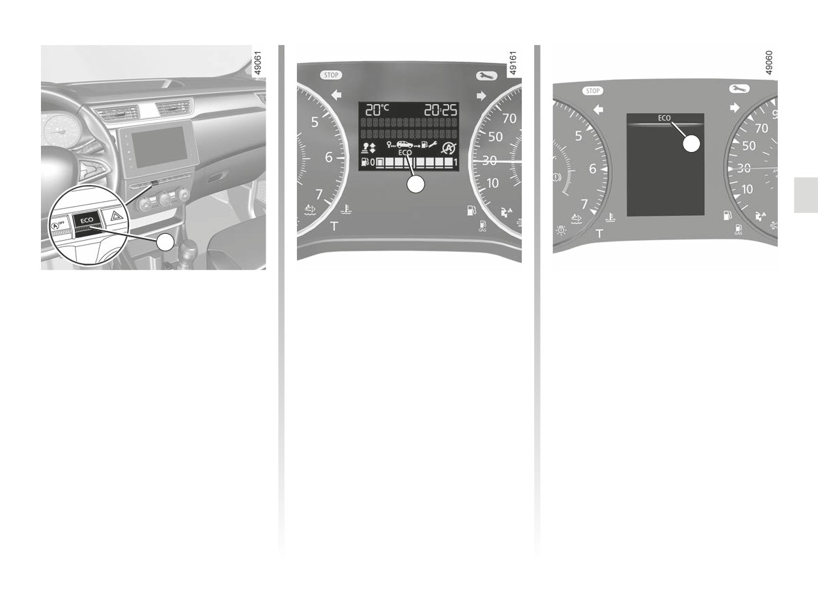
ECO mode
Activating the function
Disabling the function
Press switch 2.
ECO mode is a function which opti-
Press switch 2.
mises fuel consumption. It affects cer-
Warning light 3
goes out on the
tain driving operations (acceleration,
The 3
warning light comes on on
instrument panel to confirm deactiva-
shifting gears, cruise control, deceler-
the instrument panel to confirm activa-
tion.
ation etc.).
tion.
Limiting acceleration enables low fuel
While driving, it is possible to leave the
consumption in urban and surrounding
ECO mode temporarily in order to im-
areas.
prove engine performance.
To do this, press the accelerator pedal
firmly and fully.
ECO mode is reactivated when you
take pressure off the accelerator pedal.
2.13
CarManuals2.co
DRIVING ADVICE, ECO DRIVING (3/4)
-
High speeds significantly affect the
-
Do not try to maintain the same
vehicle’s fuel consumption.
speed up a hill, accelerate no more
than you would on the level. Keep
Examples (at a steady speed):
your foot in the same position on the
- reducing the speed from 80 mph
accelerator pedal.
(130 km/h) to 68 mph (110 km/h)
-
Double declutching and accelerating
approximately allows you to save
before switching off are unnecessary
up to around 20% of fuel;
in modern vehicles.
- reducing the speed from 56 mph
-
Bad weather, flooded roads:
(90 km/h) to 50 mph (80 km/h) ap-
proximately allows you to save up
Do not drive through
to around 10% of fuel.
floods if the water is
-
Dynamic driving with a lot of frequent
above the lower edge of
acceleration and braking is expen-
the wheel rims.
sive on fuel in comparison to the time
saved.
Driving advice, ECO driving
-
Do not overrev the engine in the in-
Behaviour
termediate gears.
- Drive carefully for the first few miles
You should always use the highest
until the engine reaches its normal
gear possible.
operating temperature, rather than
-
Avoid sudden acceleration.
let it warm up while the vehicle is sta-
tionary.
–
Brake as little as possible. If you an-
Obstructions to the driver
ticipate an obstacle or bend in ad-
On the driver’s side, only
vance, you may then simply release
use mats suitable for the
the accelerator pedal.
vehicle, attached with the
pre-fitted components, and check
the fitting regularly. Do not lay one
mat on top of another.
There is a risk of wedging the
pedals.
2.14
CarManuals2.co
DRIVING ADVICE, ECO DRIVING (4/4)
-
In vehicles fitted with air condi-
tioning, it is normal to observe an
increase in fuel consumption (espe-
cially in urban conditions) when it is
used. For vehicles fitted with manual
air conditioning, switch off the system
when it is not required.
Advice for reducing consumption
and therefore helping to preserve
the environment:
If the vehicle has been parked in the
sun, open the doors for a few mo-
ments to let the hot air escape before
starting the engine.
-
Do not leave an empty roof rack
Tyres
Advice on use
fitted to the vehicle.
-
It is better to fit a trailer for bulky ob-
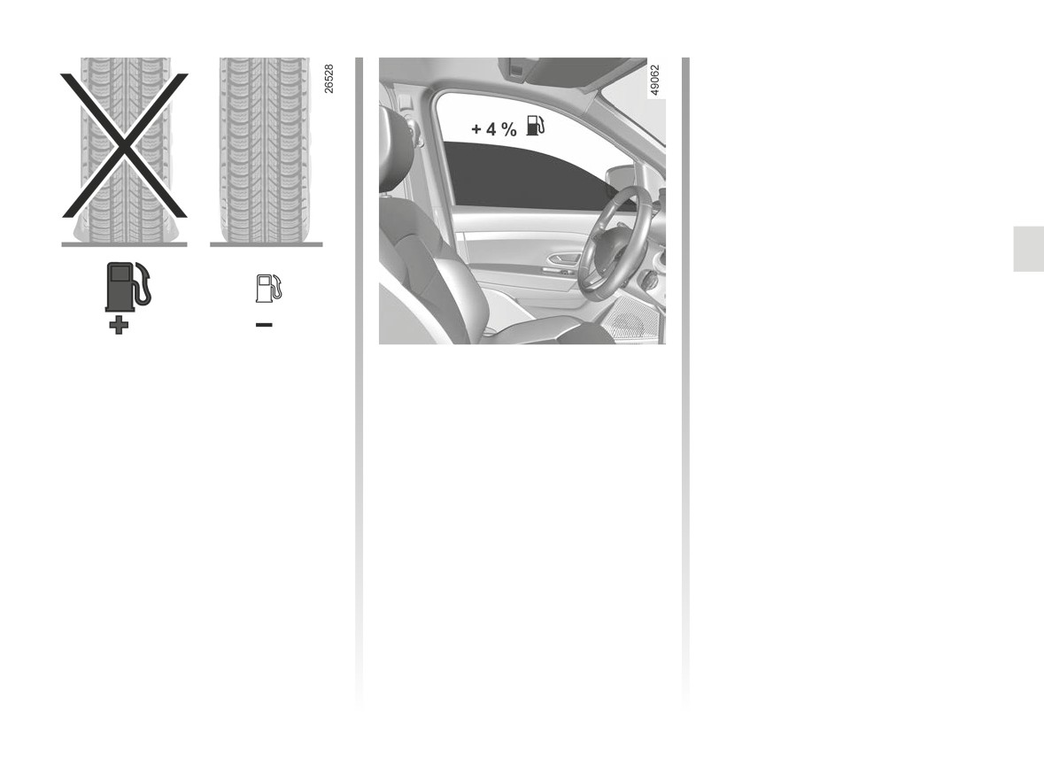
- An underinflated tyre increases fuel
- Favour the ECO mode.
jects.
consumption.
- Electricity is fuel; switch off all the
-
When towing a caravan, fit a wind
electrical components which are
- To optimise fuel consumption, set the
deflector and adjust it carefully.
not really needed. However (safety
highest speed tyre pressure or the
-
Avoid using the car for door-to-door
first), keep your lights on when the
recommended pressure indicated on
calls (short journeys with long waits
visibility is bad (“see and be seen”).
the edge of the driver’s door. ➥ 4.14.
in between) because the engine
- Use the air vents. Driving with the
never reaches its normal operating
- The use of non-recommended tyres
windows open at 60 mph (100 km/h)
temperature.
can increase fuel consumption.
will increase fuel consumption by
4%.
- Never fill the fuel tank right to the
brim to avoid overflow.
2.15
CarManuals2.co
MAINTENANCE AND ANTIPOLLUTION ADVICE
Your vehicle complies with criteria for
In addition, replacing engine, fuel
- Air filter, fuel filter: a choked ele-
recycling and recovering vehicles at the
supply system and exhaust compo-
ment will reduce efficiency. It must
end of their service life, which entered
nents with parts other than those origi-
be replaced.
into force in 2015.
nally recommended by the manufac-
- Ignition and idle speed: no adjust-
turer may alter your vehicle so that it
ment is needed.
Some parts of your vehicle have there-
no longer complies with anti-pollution
fore been designed to facilitate future
regulations.
recycling.
Exhaust gas monitoring
Have your vehicle adjusted and
These parts are easy to remove so
system
checked by an authorised dealer, in ac-
that they can be recovered and repro-
cordance with the instructions given in
The exhaust gas monitoring system will
cessed by recycling companies.
your maintenance schedule: they will
detect any operating faults in the vehi-
By virtue of its design, moderate fuel
have all the equipment necessary for
cle’s antipollution system.
consumption and initial settings, your
ensuring that your vehicle is maintained
If this system malfunctions, toxic sub-
vehicle also conforms to current an-
to its original standard.
stances may be released into the at-
tipollution regulations. The manufac-
mosphere or damage may occur.
turer is actively striving to reduce pol-
This warning light on the in-
lutant exhaust gas emissions and to
Engine adjustments
Ä
strument panel will indicate if
save energy. But the fuel consumption
- Spark plugs: for optimum condi-
there are any faults in the system:
of your vehicle and the level of pollutant
tions of use, output and performance
This lights up when the ignition is
exhaust gas emissions are also your
the specifications laid down by our
switched on and goes out when the
responsibility. Ensure that it is main-
Design Department must be strictly
engine is started.
tained and used correctly.
applied.
- If it lights up continuously, consult an
If the spark plugs have to be changed,
approved Dealer as soon as possi-
use the make, type and gap specified
Maintenance
ble;
for your vehicle’s engine. Contact an
It is important to remember that fail-
authorised dealer for this.
- if it flashes, reduce the engine speed
ure to respect antipollution regulations
until the light stops flashing. Contact
could lead to legal action being taken
an authorised dealer as soon as pos-
against the vehicle owner.
sible.
➥ 1.99
2.16
CarManuals2.co
ENVIRONMENT
Your vehicle has been designed with
Emissions
- At the end of the vehicle’s service
respect for the environment in mind for
life, it should be sent to approved
For the usage phase, your vehicle was
its entire service life: during production,
centres to ensure that it is recycled.
designed to emit fewer greenhouse
use and at the end of its life.
gases (CO2) and therefore to consume
- In all cases, comply with local legis-
less fuel.
lation.
Manufacture
Our vehicles are also equipped with a
Your vehicle has been manufactured at
particle filter system including a cata-
Recycling
a factory which complies with a policy
lytic converter, an oxygen sensor and
Your vehicle is 85% recyclable and
to reduce the environmental impact
an active carbon filter (the latter pre-
95% recoverable.
on the surrounding areas (reduction of
vents vapour from the fuel tank being
water and energy consumption, visual
released into the open air).
To achieve these objectives, many of
and noise pollution, atmospheric emis-
the vehicle components have been de-
For certain diesel vehicles, this system
sions and waste water; sorting and re-
signed to enable them to be recycled.
also has a particle filter to reduce the
using waste).
The materials and structures have
volume of soot particles emitted.
been carefully designed to allow these
components to be easily removed and
Please make your own
reprocessed by specialist companies.
contribution towards
In order to preserve raw material re-
protecting the environment
sources, this vehicle incorporates nu-
merous parts made from recycled plas-
too
tics or renewable materials (vegetable
- Worn parts replaced in the course of
or animal-derived materials such as
routine vehicle maintenance (vehi-
cotton or wool).
cle battery, oil filter, air filter, batter-
ies, etc.) and oil containers (empty or
filled with used oil) must be disposed
of through specialist organisations.
2.17
CarManuals2.co
TYRE PRESSURE MONITORING SYSTEM (1/3)
Resetting the standard level
for the tyre pressures
This should be done:
- when the standard tyre pressure
needs to be changed to adapt to
usage conditions (empty, carrying a
load, motorway driving, etc.);
- after swapping a wheel (however this
practice is not recommended);
- after changing a wheel.
1
It should always be done after checking
the tyre pressure of all four tyres when
cold.
Tyre pressures must correspond to the
current usage of the vehicle (empty,
When fitted to the vehicle, this system
carrying a load, motorway driving, etc.).
notifies the driver if one or more tyres
lose pressure.
Operating principle
This function is an addi-
Each wheel (except for the emergency
tional driving aid.
spare wheel) has a sensor in the infla-
The function does not take
tion valve which periodically measures
the place of the driver. It
the tyre pressure while driving.
cannot, therefore, under any cir-
cumstances replace the vigilance or
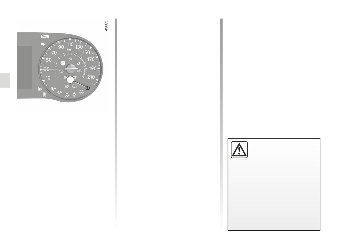
Warning light
1 comes on to
the responsibility of the driver.
alert the driver in the event of insuffi-
cient pressure (deflated wheel, punc-
Check the tyre pressures, including
tured tyre, etc.).
the emergency spare wheel, once a
month.
2.18
CarManuals2.co
TYRE PRESSURE MONITORING SYSTEM (2/3)
Note: the standard tyre pressure
« PUNCTURE »
2
cannot be less than that recommended
and indicated on the door frame.
The warning light
comes on
steady, accompanied by the message
“PUNCTURE” and a beep.
Display
This message appears along with the
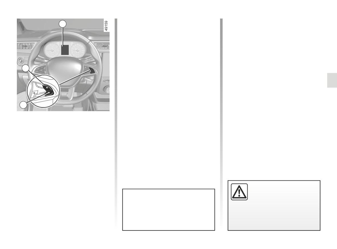
Display 2 on the instrument panel in-
®
warning light.
forms you of any tyre pressure faults
3
(flat tyre, punctured tyre, etc.).
They indicate that at least one wheel
is punctured or severely underinflated.
« ADJUST TYRE PRESSURE »
Replace it or contact an approved
dealer if it is punctured. Top up the tyre
Warning light
comes on, along
pressure if the wheel is deflated.
with the message
“ADJUST TYRE
PRESSURE”.
4
These indicate that at least one tyre is
flat.
Resetting procedure
Ignition on, vehicle stationary:
Check and, if necessary, readjust the
- repeatedly press button 3 or 4 to
pressures of the four wheels when cold.
select the “Tyre pressure init. long
The warning light
goes off after a
press” function on the display 2;
few minutes’ driving.
- press and hold (around 3 seconds)
button 3 or 4 to start initialisation.
Display of the message “PRESSURE
REF ONGOING” indicates that the
reset request for the tyre pressure
reference value has been taken into
account.
Reinitialisation is carried out after a few
Warning light
®
re-
minutes’ driving.
quires you to stop immedi-
ately, for your own safety,
The sudden loss of pressure in a
as soon as traffic conditions
tyre (burst tyre, etc.) cannot be de-
allow.
tected by the system.
2.19
CarManuals2.co
TYRE PRESSURE MONITORING SYSTEM (3/3)
« CHECK TYRE PRESSURE
Replacing wheels/tyres
Tyre repair product and
SENSORS »
This system requires specific equip-
inflation kit
ment (wheels, tyres, hubcaps, etc.)
As the valves are specifically designed,
The warning light
flashes for
➥ 5.13.
only use equipment approved by the
several seconds, then stays on, along
Contact an approved Dealer to fit new
approved network ➥ 5.6.
with the message
“CHECK TYRE
PRESSURE SENSORS”.
tyres and to find out about available ac-
cessories compatible with the system
This message appears along with the
and available from your dealer net-
warning light.
work: the use of any other accessory
They indicate that at least one tyre is
could affect the correct operation of the
not fitted with sensors (e.g. emergency
system or damage a sensor.
spare wheel). Otherwise, consult an
authorised dealer.
Emergency spare wheel
If the vehicle is equipped with an emer-
Readjustment of tyre
gency spare wheel, it will not have a
pressures
sensor. When it is fitted on the vehicle,
The tyre pressures must be adjusted
the warning light
flashes for sev-
when cold (please refer to the label lo-
eral seconds, then stays on, together
cated on the edge of the driver’s door).
with the warning light
and the
If tyre pressures cannot be checked
message “CHECK TYRE PRESSURE
when the tyres are cold, the recom-
SENSORS” appears on the instrument
mended pressures must be increased
panel.
by 0.2 to 0.3 bar (3 PSI).
Changing a wheel
Never deflate a hot tyre.
The system may take sev-
eral minutes depending on
use for the new wheel pres-
sures to be recognised; check the
tyre pressures after all operations.
2.20
CarManuals2.co
GEAR LEVER, HANDBRAKE
Handbrake
An impact to the under-
side of the vehicle while
To release
manoeuvring
(e.g.: strik-
1
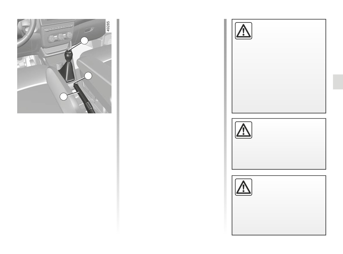
Pull lever 3 up slightly, press button 2
ing a post, raised kerb or
and then lower the lever to the floor.
other street furniture) may result in
damage to the vehicle (e.g.: defor-
The warning light }
on the instru-
mation of an axle).
ment panel will go out.
The red warning light on the instrument
To prevent any risk of accident,
2
panel will come on if you are driving
have your vehicle checked by an
with an incorrectly released handbrake.
approved dealer.
To apply
3
Pull the lever 3 upwards and make sure
the vehicle is immobilised. The warning
Selecting reverse gear
light }
on the instrument panel will
(vehicle stationary)
come on.
Make sure that the hand-
brake is properly released
Follow the grid marked on knob 1 and,
when driving (red indicator
depending on the vehicle, lift the ring
light off), otherwise over-
against the knob to engage reverse
heating, or even damage, may
gear.
occur.
The reversing lights will come on as
soon as reverse gear is selected with
the ignition on.
Depending on the gradient
and/or vehicle load, it may
be necessary when station-
ary to apply the brake by
at least a further two notches and
engage a gear (1st or reverse gear).
2.21
CarManuals2.co
REAR CAMERA (1/3)
1
2
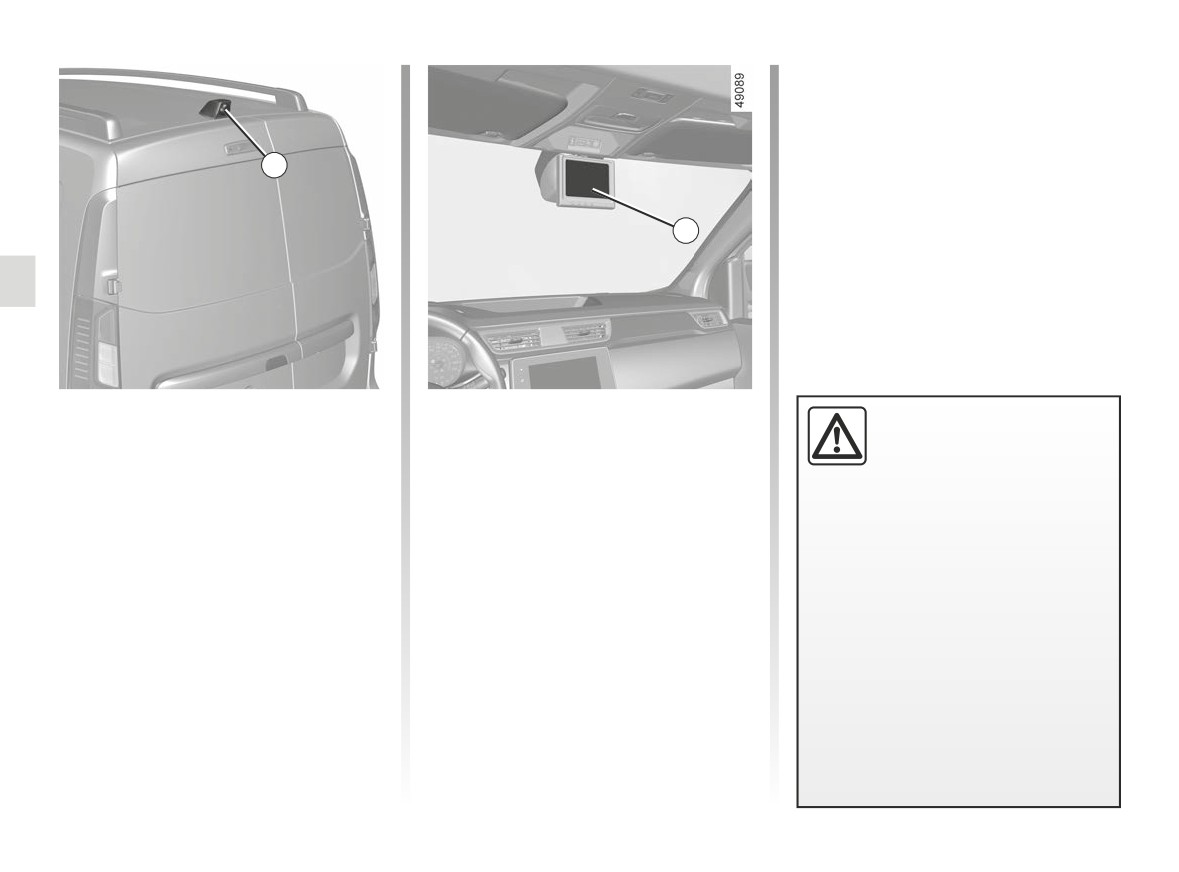
When the vehicle ignition is switched
Special features
This function is an additional
on, the screen 2 fixed to the wind-
The camera is equipped with an auto-
aid. It cannot, therefore,
screen will display a warning message
matic de-icer which is activated when
under any circumstances
for approximately five seconds, then it
the temperature is below approximately
replace the vigilance or the
will display the view behind the vehicle
8°C.
responsibility of the driver.
using the camera 1.
Make sure that the 1 camera is not ob-
The driver should always be ready
Note: the screen 2 can be positioned
scured (by dirt, mud, snow, condensa-
for sudden incidents while driv-
left to right or top to bottom.
tion etc.).
ing: always ensure that there are
no small, narrow moving obstacles
(such as a child, animal, pushchair,
bicycle, stone, post, etc.) in the blind
spot when manoeuvring.
2.22
CarManuals2.co
REAR CAMERA (2/3)
Switching off the function
The display switches of:
- immediately when engaging reverse
gear;
- 30 seconds after the ignition is
2
switched off.
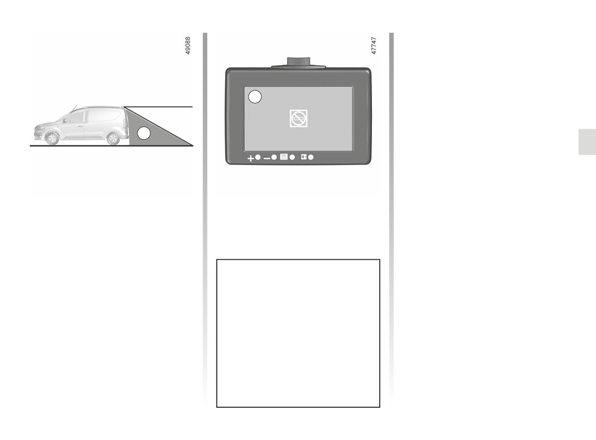
A
Operation
The camera’s field of vision does not
cover the entire area behind the vehi-
cle, particularly the blind spot area A.
On vehicles equipped with the Stop
and Start function, the display remains
active when the engine is in standby.
➥ 2.5.
Objects which appear on the edge
of screen 2 may be deformed.
In very bright light (snow, vehicle
in sunshine, etc.), the camera view
may be partially disturbed.
In low brightness or poor weather,
the image on the screen may be dis-
torted.
2.23
CarManuals2.co
REAR CAMERA (3/3)
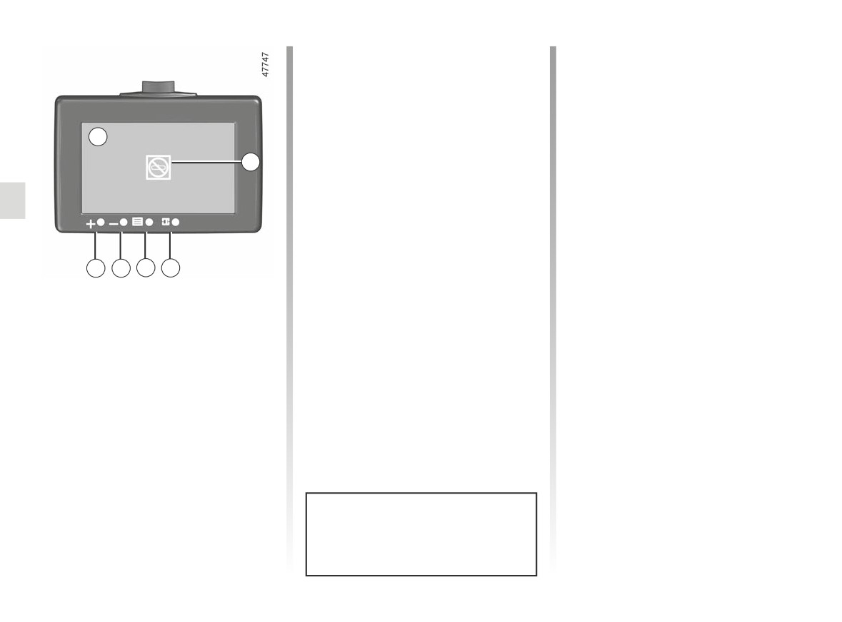
Adjustment of brightness modes
Operating faults
Once the mode has been selected,
When the system detects an operating
press button 5as many times as re-
fault, warning light B appears temporar-
quired to access the type of setting you
ily on screen 2.
wish to change:
This may be caused a temporary fault
- brightness;
2
affecting the camera or screen (clear-
- contrast;
ness, fixed image, delayed communi-
B
- colour;
cation, etc.).
- RESET: resets factory settings.
If the warning light remains on, consult
Press buttons 3 (+) or 4 (-) to adjust the
an approved dealer.
setting.
Note: only the first three modes (“day”,
“intermediary” and “night”) can be set.
3
4
5
6
Adjustment of the display
Accessing the brightness modes
Press button 6 repeatedly to select one
of the four preset brightness modes:
- “day” mode;
- “intermediary” mode;
- “night” mode;
- “black screen” mode: allows suspen-
sion of the display. Screen 2 displays
a black image accompanied by the
“OFF” message. To exit this mode,
press button 6 again to access the
first brightness mode (“day” mode).
Each time the vehicle is started,
the function returns to the settings
saved at the last engine stop.
2.24
CarManuals2.co
DRIVER CORRECTION DEVICES, AIDS (1/5)
Depending on the vehicle, this is com-
Anti-lock braking system
Operating faults:
posed of:
(ABS)
-
and x
lit up on the in-
–
anti-lock braking system (ABS);
Under heavy braking, the ABS prevents
strument panel accompanied by the
-
electronic stability program (ESC)
the wheels from locking, allowing the
messages “CHECK ABS”, “CHECK
with understeer control and trac-
stopping distance to be managed and
BRAKING SYSTEM” and “Check
tion control;
keeping control of the vehicle.
ESC”: this indicates that the ABS,
Under these circumstances, the vehi-
the ESC and the emergency brake
-
emergency brake assist;
cle can be steered to avoid an obstacle
assist are disabled. Braking is
-
hill start assist;
whilst braking. In addition, this system
always enabled;
can increase stopping distances, par-
–
driver assistance with a trailer;
ticularly on roads with low surface grip
- x
, D
-
of the traction control - Extended
(wet ground, etc.).
up on the instrument panel alongside
grip.
You will feel a pulsation through the
the message “Braking system fault”:
brake pedal each time the system is
this indicates a fault in the braking
activated. The ABS does not in any
system.
way improve the vehicle’s physical per-
In both cases, please consult an
formance relating to the road surface
Authorised Dealer.
and road-holding. It is still essential to
follow the rules of good driving practice
(such as driving at a safe distance from
the vehicle in front, etc.).
Your braking systems
are partially operational.
However, it is dangerous
In an emergency, apply firm and
to brake suddenly and
continuous pressure to the brake
it is essential to stop immediately,
pedal. There is no need to pump
as soon as traffic conditions allow.
it repeatedly. The ABS will modu-
Contact an approved dealer.
late the force applied in the braking
system.
2.25
CarManuals2.co
DRIVER CORRECTION DEVICES, AIDS (2/5)
Electronic stability control
Understeer control
Operating faults
(ESC) with understeer control
This system optimises the action of the
When the system detects an operat-
and traction control
ESC in the case of pronounced under-
ing fault the message “Check ESC” and
steering (loss of front axle road hold-
appear
Electronic stability control ESC
ing).
on the instrument panel. In this case,
This system helps you to keep control
Traction control
the ESC and traction control system
of the vehicle in critical driving condi-
are deactivated.
tions (avoiding an obstacle, loss of grip
This system helps to limit wheelspin of
Consult an approved dealer.
on a bend, etc.).
the drive wheels and to control the ve-
hicle when pulling away accelerating or
Operating principle
decelerating.
A sensor in the steering wheel detects
Operating principle
the direction selected by the driver.
Using the wheel sensors, the system
These functions are an ad-
Other sensors throughout the vehicle
measures and compares the speed of
ditional aid in the event of
measure the actual direction.
the drive wheels at all times and slows
critical driving conditions,
down their over-rotation. If a wheel is
The system compares driver input to
enabling the vehicle behav-
starting to slip, the system brakes au-
the actual trajectory of the vehicle and
iour to be adapted to suit the driving
tomatically until the drive supplied be-
corrects the trajectory if necessary by
conditions.
comes compatible with the level of grip
controlling the braking of certain wheels
under the wheel again.
The functions do not take the place
and/or engine power. In the event that
of the driver. They do not increase
the system is engaged, indicator light
The system also adjusts the engine
the vehicle’s limits and should
speed to the grip available under the
flashes on the instrument panel.
not encourage you to drive more
wheels, independently of the pressure
quickly. Therefore, they can under
exerted on the accelerator pedal.
no circumstances replace the vigi-
lance or responsibility of the driver
when manoeuvring the vehicle (the
driver must always be ready for
sudden incidents which may occur
when driving).
2.26
CarManuals2.co
DRIVER CORRECTION DEVICES, AIDS (3/5)
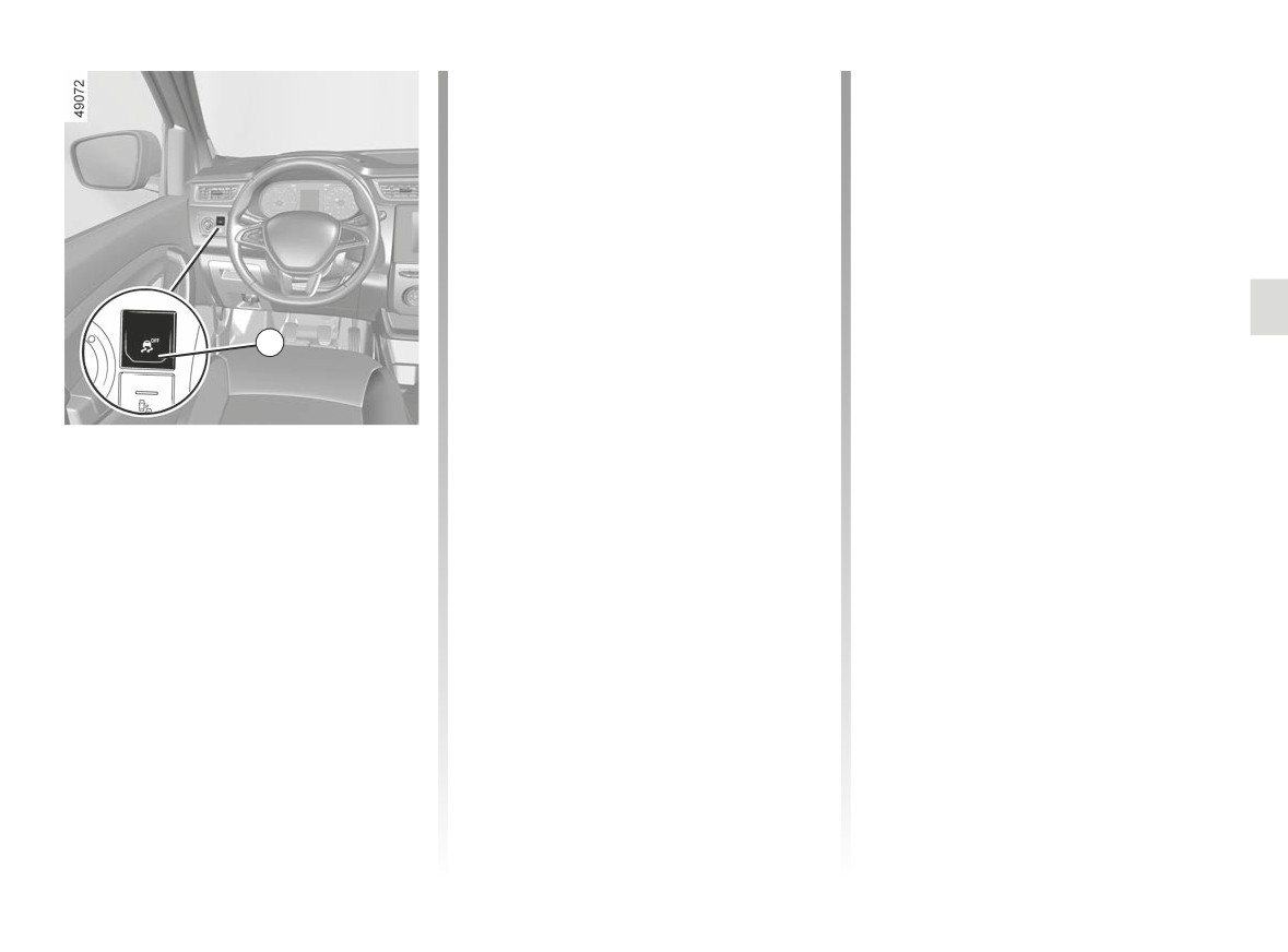
The traction control system offers ad-
Hazard warning lights switching on
ditional safety. It is recommended that
Depending on the vehicle, these may
you do not drive with the function disa-
light up in the event of sudden decel-
bled. Correct this as soon as possible
eration.
by pressing the switch 1 again.
Operating faults
Note: The function is reactivated auto-
matically when the ignition is switched
When the system detects an operating
on or when a speed of approximately
fault the message “CHECK BRAKING
30 mph (50 km/h) is exceeded.
SYSTEM” appears on the instrument
panel along with the
warning
light.
Emergency brake assist
1
Consult an approved dealer.
This is an additional system to ABS
which helps reduce vehicle stopping
distances.
Disabling the traction control
Operating principle
system
The system is for detecting an emer-
In some situations (driving on very wet
gency braking situation. In this case,
ground: snow, mud, etc. or driving with
the braking system immediately devel-
snow chains fitted), the system may
ops maximum power and may trigger
reduce the engine output to limit wheel-
ABS regulation.
spin. If this is not required, it is possible
ABS braking is maintained as long as
to deactivate the function by pressing
the brake pedal is not released.
switch 1. In this case, the warning light
comes on steady on the instru-
ment panel accompanied by the mes-
sage “ESC OFF”. This action does not
deactivate the ESC.
2.27
CarManuals2.co
DRIVER CORRECTION DEVICES, AIDS (4/5)
Hill start assistance
Driver assistance with a
Depending on the gradient of the in-
trailer
cline, this system assists the driver
This system helps to maintain control
when starting on a hill. It prevents the
over the vehicle while using a trailer.
The hill start assistance
vehicle from rolling backwards by au-
It detects shaking caused by towing a
system cannot completely
tomatically applying the brakes when
trailer under certain driving conditions.
prevent the vehicle from
the driver lifts his/her foot off the brake
rolling backwards in all sit-
Operating conditions
pedal to depress the accelerator pedal.
uations (extremely steep gradients
- The towbar must be approved by an
etc.).
System operation
authorised dealer;
In all cases, the driver may depress
- the harness must be approved by an
It only operates when the gear lever is
the brake pedal to prevent the vehi-
authorised dealer;
in a position other than neutral and the
cle from rolling backwards.
- the towbar must be connected to the
vehicle is completely stationary (brake
vehicle.
pedal depressed).
The hill start assistance function
Operating principle
should not be used for prolonged
The system holds the vehicle for ap-
The function stabilises the vehicle by:
stops: use the brake pedal.
proximately 2 seconds. The brakes are
- asymmetric braking of the front
then gradually released (the vehicle will
This function is not designed to im-
wheels to reduce shaking caused by
move according to the slope).
mobilise the vehicle permanently.
the trailer;
- braking of all four wheels and limita-
If necessary, use the brake pedal to
tion on engine torque to reduce the
stop the vehicle.
vehicle speed until the shaking has
The driver must remain particularly
stopped.
vigilant when driving on slippery or
low-grip surfaces.
Warning light
flashes on the in-
strument panel to inform the driver.
Risk of serious injury.
2.28
CarManuals2.co
DRIVER CORRECTION DEVICES, AIDS (5/5)
Traction control - Extended
“Soft ground” mode
grip
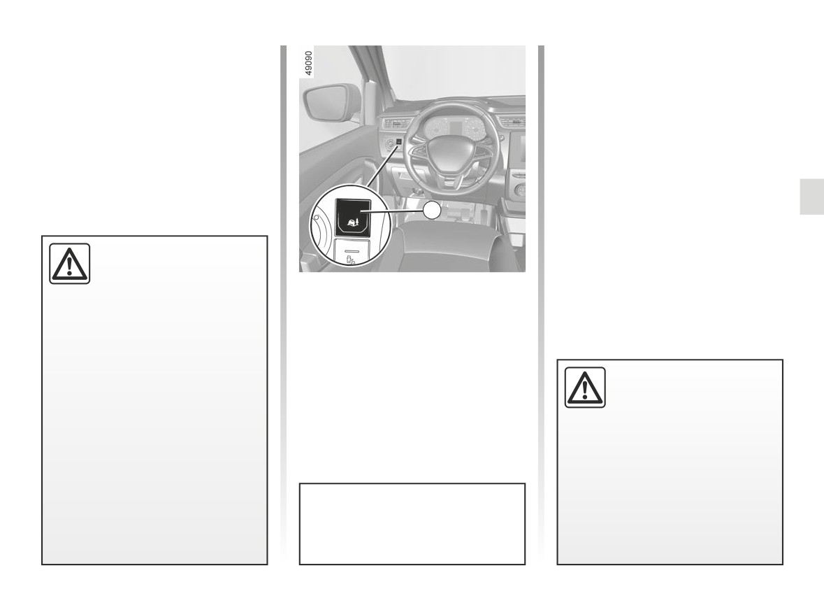
Press the 2 switch: the message “Grip
Extend Loose Surface ON” is displayed
If fitted on the vehicle, grip control
on the instrument panel.
makes it easier to control the vehicle on
low grip surfaces (soft ground, etc.).
This position enables optimal usage on
soft ground (mud, sand, dead leaves,
etc.). In this position, engine speed is
left under the driver’s control.
The system automatically switches to
“Road” mode at speeds above about
2
31 mph (50 km/h). The message
“Standard road mode on” is displayed
on the instrument panel to warn you.
These functions are an ad-
ditional aid in the event of
critical driving conditions,
“Road” mode
enabling the vehicle behav-
When the vehicle starts, the message
iour to be adapted to suit the driving
“Standard road mode on” is displayed
conditions.
on the instrument panel.
The functions do not take the place
The default mode Road enables opti-
of the driver. They do not increase
mal use under normal road conditions
the vehicle’s limits and should
Tyres
(dry, wet, light snow, etc.).
not encourage you to drive more
When they need to be re-
“Road” mode uses traction control func-
quickly. Therefore, they can under
placed, only tyres of the
tions.
no circumstances replace the vigi-
same make, size, type and
lance or responsibility of the driver
profile should be used.
when manoeuvring the vehicle (the
Tyres fitted to the vehicle should
driver must always be ready for
either be identical to those fitted
sudden incidents which may occur
originally or conform to those
when driving).
recommended by your approved
dealer.
After the engine stops, the vehicle
will always restart in “Road” mode.
2.29
CarManuals2.co
SPEED LIMITER (1/3)
5
1
2
3
4
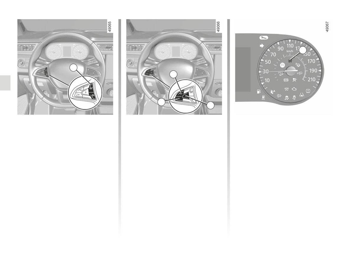
The speed limiter function helps you
Controls
Switching on
stay within the driving speed limit that
1 Main “On/Off” switch.
Press switch 1 on the side showing
you choose, known as the limit speed.
. The warning light 5 illuminates in
2 Reminder of the stored limit speed
orange and, depending on the vehi-
and increase of the limit speed
cle, the message “Speed limiter ON”
(RES/+).
or “Speed Limiter XXX mph (km/h)” ap-
3 Limit speed activation, storage and
pears on the instrument panel accom-
decrease switch (SET/-).
panied by dashes to indicate that the
4 Speed limiter function standby (with
speed limiter function is activated and
limited speed memory) (0).
waiting to store a limit speed.
To store the current speed, press
switch 3 (SET/-): the limited speed re-
places the dashes.
The minimum stored speed is 20 mph
(30 km/h).
2.30
CarManuals2.co
SPEED LIMITER (2/3)
Varying the limit speed
Exceeding the limit speed
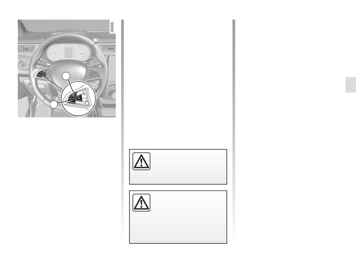
The limit speed may be changed by re-
It is possible to exceed the limit speed
peatedly pressing:
at any time. To do this: press the accel-
erator pedal firmly and fully (beyond
-
switch 2 (RES/+) to increase speed;
the resistance point).
-
switch 3 (SET/-) to reduce speed.
While the speed is being exceeded, the
programmed speed displayed on the
instrument panel flashes.
2
Then, release the accelerator: the
speed limiter function will return as
soon as you reach a speed lower than
the stored speed.
3
Limited speed cannot be maintained
When driving down a steep gradient,
Driving
the system may be unable to maintain
When a limited speed has been stored
the limited speed: the limited speed
and provided this speed is not reached,
will flash on the instrument panel and,
driving is similar to driving a vehicle
depending on the vehicle, an audible
without the speed limiter function.
signal will sound at regular intervals to
The speed limiter function is
inform you of this situation.
Once you have reached the stored
in no way linked to the brak-
speed, no effort on the accelera-
ing system.
tor pedal will allow you to exceed
the programmed speed except in an
emergency (refer to information on
“Exceeding the limit speed”).
If the speed limiter is not
available (after several at-
tempts to activate), contact
an approved dealer.
2.31
CarManuals2.co
SPEED LIMITER (3/3)
Recalling the limit speed
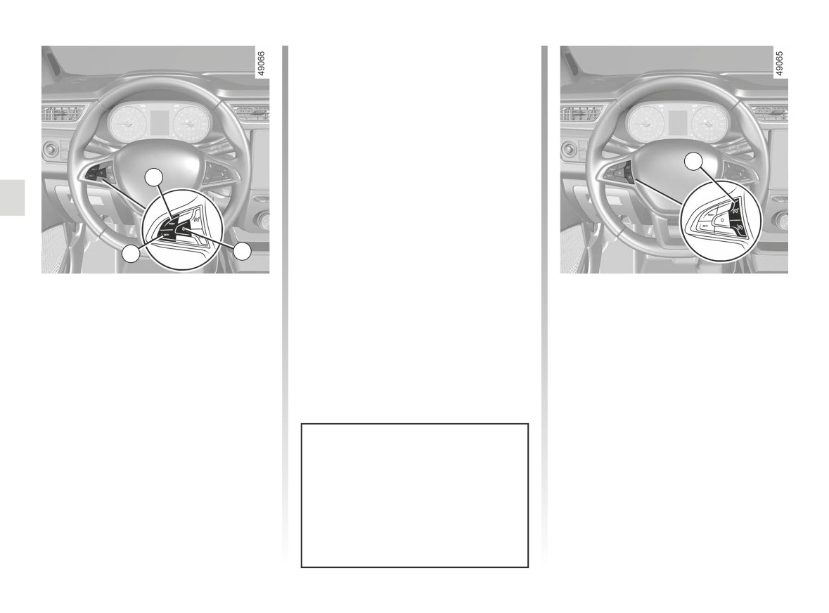
If a speed has been stored, it can be
recalled by pressing switch 2 (RES/+).
1
2
3
4
Putting the function on
Switching off the function
standby
The speed limiter function is deac-
The speed limiter function is sus-
tivated if you press switch 1: in this
pended when you press switch 4 (0).
case a speed is no longer stored. The
The limit speed remains stored and,
orange instrument panel warning light
depending on the vehicle, the message
goes out, confirming that the func-
“Memorised XXX mph (XXX km/h)” ap-
tion is stopped.
pears on the instrument panel accom-
panied by the stored speed.
When the speed limiter is set to
standby, pressing switch 3 (SET/-)
reactivates the function without
taking into account the memorised
speed: it is the speed at which the
vehicle is moving that is taken into
account.
2.32
CarManuals2.co
CRUISE CONTROL (1/4)
1
2
This function is an addi-
tional driving aid.
3
4
It can under no circum-
stances replace the driver’s
The cruise control function helps you to
Controls
responsibility to respect speed limits
maintain your driving speed at a speed
or to be vigilant.
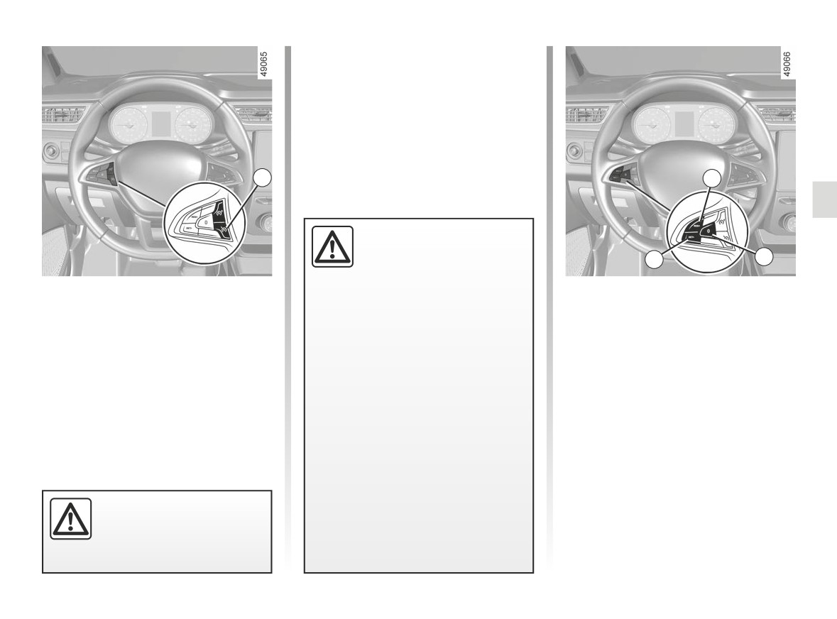
1 Main “On/Off” switch.
that you choose, called the cruising
speed.
The driver must always be in control
2 Reminder of the stored cruising
of the vehicle.
speed and increase to cruising
This cruising speed may be set at any
speed (RES/+).
speed above 20 mph (30 km/h).
Cruise control must not be used
in heavy traffic, on winding or slip-
3 Cruising speed activation, storage
pery roads (black ice, aquaplan-
and decrease switch (SET/-).
ing, gravel) and during bad weather
4 Switch the function to standby (with
(fog, rain, side winds etc.).
cruising speed saved) (0).
There is a risk of accidents.
The cruise control function
is in no way linked to the
braking system.
2.33
CarManuals2.co
CRUISE CONTROL (2/4)
6
5
1
3
Switching on
Activating cruise control
Driving
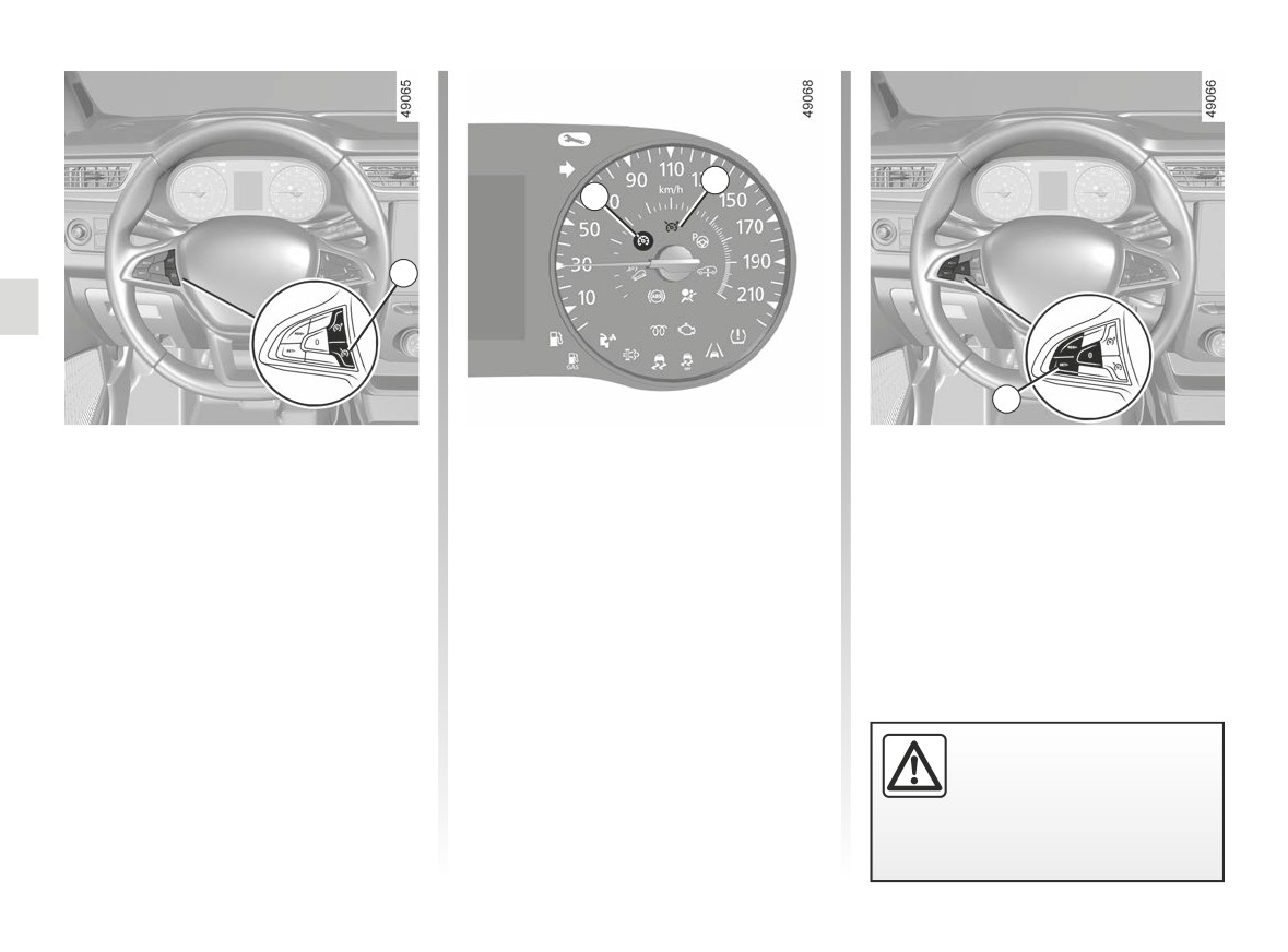
Press switch 1 on the side showing .
At a steady speed (above approxi-
Once a cruising speed is stored and
mately 19 mph (30 km/h)) press the
the cruise control function is active,
The 6 warning light appears in green
switch 3 (SET/-): the function is acti-
you may lift your foot off the accelera-
and, depending on the vehicle, the
vated and the current speed is stored.
tor pedal.
message “Cruise control ON” or “Cruise
Control --- mph (--- km/h)” appears on
The cruising speed replaces the dashes
the instrument panel, accompanied by
and the cruise control function is con-
dashes to indicate that the cruise con-
firmed by the appearance, depending
trol function is in operation and waiting
on the vehicle, of the message “Cruise
to memorise a cruising speed.
control ON” or “Cruise Control XXX
mph (XXX km/h)” and the 5 warn-
ing light in green, in addition to the 6
warning light.
Please note that you must
keep your feet close to the
pedals in order to react in
an emergency.
2.34
CarManuals2.co
CRUISE CONTROL (3/4)
Exceeding the cruising speed
The cruising speed may be exceeded
at any time by depressing the accelera-
tor pedal.
While it is being exceeded, the cruising
speed flashes on the instrument panel.
Then, release the accelerator: after a
2
few seconds, the vehicle will automati-
cally return to its set cruising speed.
Cruising speed cannot be
maintained
When driving down a steep gradient,
3
the system may be unable to maintain
the cruising speed: the stored speed
Adjusting the cruising speed
will flash on the instrument panel infor-
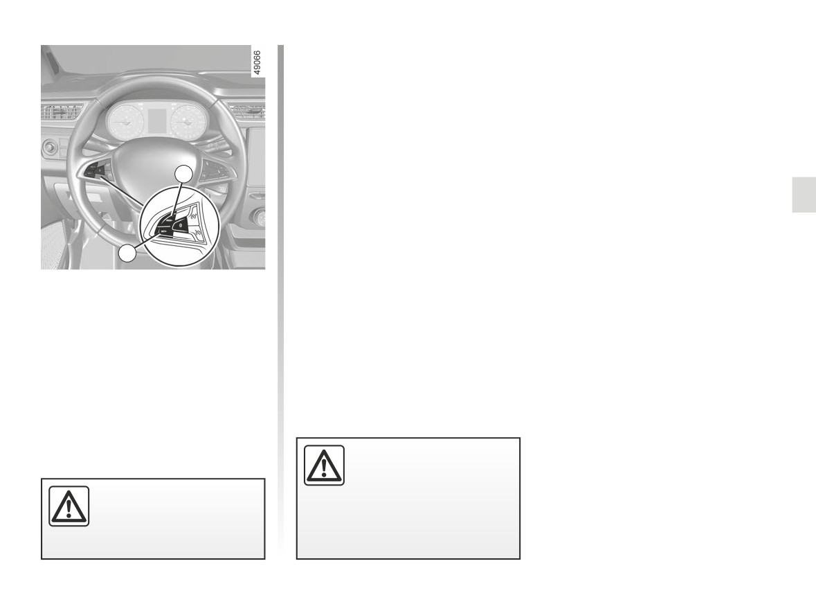
The cruising speed may be changed by
mation display to inform you of this sit-
pressing the following repeatedly:
uation.
- switch 2 (RES/+) to increase speed;
- switch 3 (SET/-) to reduce speed.
If the cruise control is no
longer available (after sev-
eral attempts to activate it),
The cruise control function
contact an approved dealer.
is in no way linked to the
braking system.
2.35
CarManuals2.co
CRUISE CONTROL (4/4)
Returning to the cruising speed
If a speed is stored, it can be recalled,
once you are sure that the road condi-
tions are suitable (traffic, road surface,
weather conditions, etc.). Press the
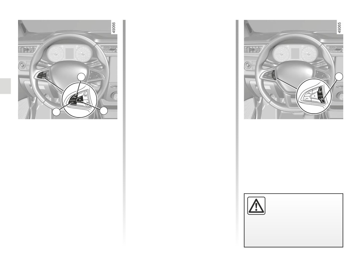
switch 2 (RES/+) if the vehicle speed is
above 19 mph (30 km/h).
When the stored speed is recalled, acti-
2
vation of the cruise control is confirmed
1
by the illumination of the warning
light.
Note: if the speed previously stored is
much higher than the current speed,
3
4
the vehicle will accelerate more rapidly
to reach this threshold.
Putting the function on
When the cruise control is set to
Switching off the function
standby
standby, pressing switch 3 (SET/-) re-
The cruise control function is deacti-
activates the cruise control function
The function is set to standby if you:
vated if you press the 1 switch. In
without taking into account the stored
this case a speed is no longer stored.
- use the switch 4 (0);
speed: it is the speed at which the vehi-
The two instrument panel warning
cle is moving that is taken into account.
- the brake pedal;
lights and go out to confirm that
- the clutch pedal;
the function is deactivated.
In all three cases, the cruising speed
remains stored and, depending on the
vehicle, the message
“Memorised
XXX mph (XXX km/h)” appears on the
Putting the cruise control
instrument panel.
on standby or switching it
Standby is confirmed when indicator
off does not cause a rapid
light goes out.
reduction in speed: you
must brake by depressing the brake
pedal.
2.36
CarManuals2.co
PARKING DISTANCE CONTROL (1/5)
Operating principle
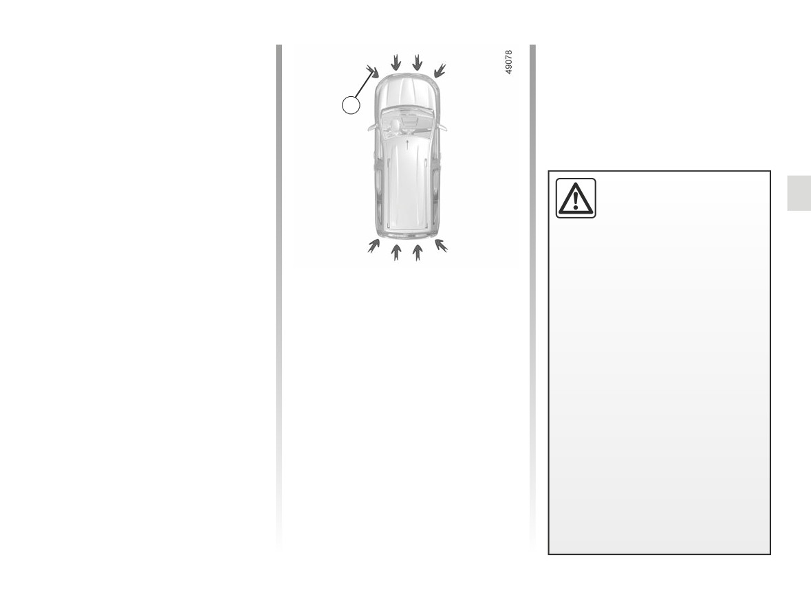
Ultrasonic sensors, indicated by
arrows 1, are fitted in the bumpers to
measure the distance between the ve-
1
hicle and an obstacle.
This measurement is indicated by
beeps which become more frequent the
closer you come to the obstacle, until
they become a continuous beep when
This function is an addi-
the vehicle is approximately
20 to
tional driving aid.
30 centimetres from the obstacle.
Under no circumstances
The system detects obstacles to the
should it replace the driv-
front, the rear and the sides of the ve-
er’s care or responsibility whilst re-
hicle.
versing.
The parking distance control system
Location of the ultrasonic sensors
The driver should always be ready
is only activated when the vehicle is
Ensure that the ultrasonic sensors indi-
for sudden incidents while driv-
driven at a speed below approximately
cated by the arrows 1 are not obscured
ing: always ensure that there are
6 mph (10 km/h).
(by dirt, mud, snow, a badly fitted/at-
no small, narrow moving obstacles
The parking distance control system
tached number plate), impacted, mod-
(such as a child, animal, pushchair,
does not take into account towing and
ified (including paintwork) or obstructed
bicycle, stone, post etc.) in the blind
load carrying systems etc.
by any accessory fitted to the rear and/
spot when manoeuvring.
or, depending on the vehicle, to the
front or sides of your vehicle.
2.37
CarManuals2.co
PARKING DISTANCE CONTROL (2/5)
Operation
2
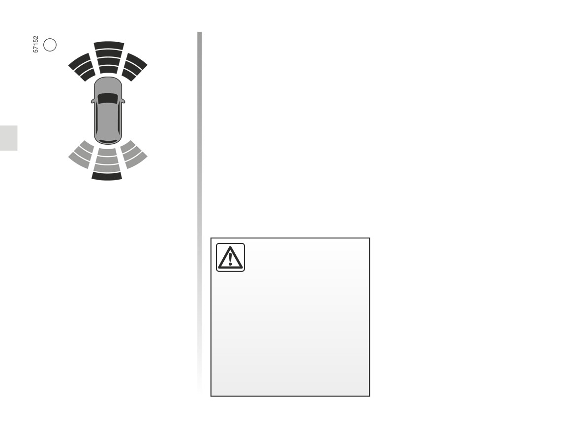
Most objects located near the rear and,
depending on the vehicle, near the front
end are detected.
Depending on the vehicle, the areas
will be shown on the 2 display.
Note: in the event of a change in tra-
jectory during a manoeuvre, the risk of
collision with an obstacles may be sig-
nalled late.
Note: the display 2 shows the vehicle
surroundings and emits beeps.
An impact to the under-
side of the vehicle while
manoeuvring
(e.g.: strik-
ing a post, raised kerb or
other street furniture) may result in
damage to the vehicle (e.g.: defor-
mation of an axle).
To avoid any risk of accident, have
your vehicle checked by an ap-
proved Dealer.
2.38
CarManuals2.co
PARKING DISTANCE CONTROL (3/5)
You must disable the function if:
Operating faults
- towing, carrying or trailer equipment
Depending on the vehicle, when the
is present in front of the ultrasonic
system detects an operating fault, the
detectors;
message “Parking sensors to check”
appears on the instrument panel, ac-
- in the event of damage to the ultra-
sonic sensors.
companied by the warning light
and a beep lasting approximately 5 sec-
Automatic deactivation of the
onds. Consult an approved dealer.
parking distance control
The system deactivates:
-
when the vehicle speed is above ap-
proximately 6 mph (10 km/h);
3
-
depending on the model, when the
vehicle is stationary for more than
Deactivating the system
approximately 5 seconds and an ob-
stacle is detected (such as when in a
Deactivating the parking distance
traffic jam, etc.);
control manually
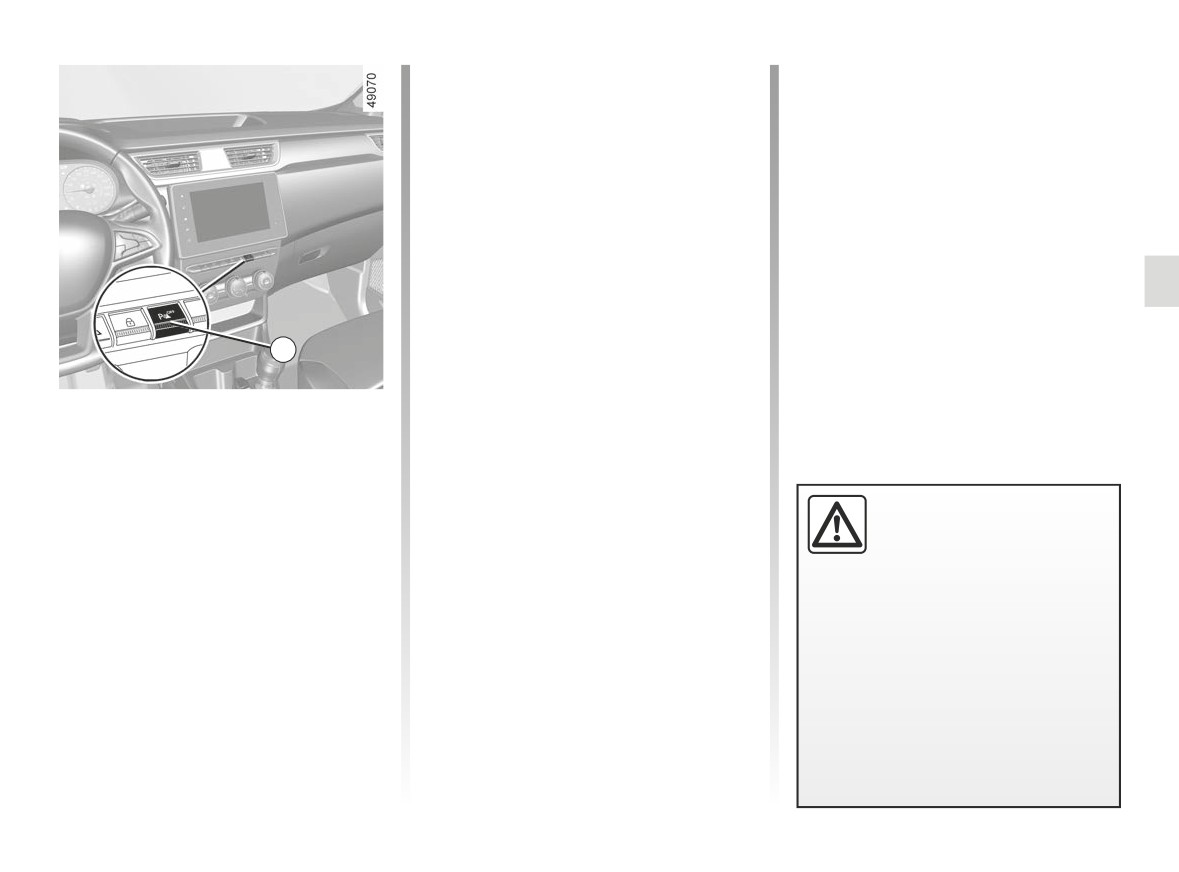
-
when you are in neutral;
Press switch 3 to deactivate the system.
–
when an operating fault is detected.
An impact to the under-
The switch warning light 3 appears to
side of the vehicle while
indicate that the system is deactivated.
manoeuvring
(e.g.: strik-
ing a post, raised kerb or
Pressing the switch again will reacti-
other street furniture) may result in
vate the system and switch off the in-
damage to the vehicle (e.g.: defor-
dicator light.
mation of an axle).
To avoid any risk of accident, have
your vehicle checked by an ap-
proved Dealer.
2.39
CarManuals2.co
PARKING DISTANCE CONTROL (4/5)
System servicing/repairs
- In the event of an impact, the alignment of the sensors may be altered and their operation may consequently be affected.
Deactivate the function and consult an authorised dealer.
- Any work in the area where the sensors are located (repairs, replacements, etc.) must be carried out by a qualified profes-
sional.
Only an authorised dealer is qualified to service the system.
System disturbance
Some conditions can disrupt or damage the operation of the system, for example:
- poor weather conditions (rain, snow, hail, black ice, etc.);
- in the event of exposure to strong electromagnetic waves (under high-voltage lines, etc.);
- some types of noise (motorcycle, lorry, pneumatic drill etc.);
- fitting a non-compatible towing ball or hook;
- ...
Risk of false alarms or absence of warnings
In the event of the system behaving abnormally, deactivate it and consult an authorised dealer.
2.40
CarManuals2.co
PARKING DISTANCE CONTROL (5/5)
Limitation of the system operation
- The area around the sensors must be kept clean and free of any modifications in order to ensure the proper operation of the
system.
- Small objects moving close to the vehicle (motorcycles, bicycles, pedestrians, etc.) may not be recognised by the system.
- The system may not detect objects that are too close to the vehicle.
- The system may not provide a warning when the other vehicles or objects are travelling at a significantly different speed.
- When there is a change in trajectory during a manoeuvre, the system may be slow in reporting obstacles.
- When the vehicle is towing a trailer, the rear Park Assist system must be deactivated.
Deactivating the function
You must deactivate the function if the sensor area has been damaged.
2.41
CarManuals2.co
REVERSING CAMERA (1/3)
2
3
1
Operation
Note: depending on the vehicle, certain
settings can be adjusted from the multi-
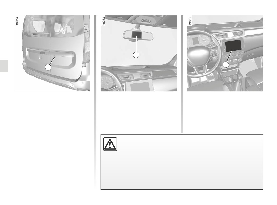
Moving into reverse gear, the camera 1
media screen 3. Refer to the handbook
located on the rear hinged door pro-
for the equipment.
vides a view of the area behind the
vehicle on the rear view mirror 2 or,
depending on the vehicle, on the mul-
timedia screen 3, accompanied by one
or two (moving and fixed) guide lines 4
and 5.
This function is an additional aid. It cannot, therefore, under any circum-
stances replace the vigilance or the responsibility of the driver.
The driver should always be ready for sudden incidents while driving:
always ensure that there are no small, narrow moving obstacles (such
as a child, animal, pushchair, bicycle, stone, post, etc.) in the blind spot when
manoeuvring.
2.42
CarManuals2.co
REVERSING CAMERA (2/3)
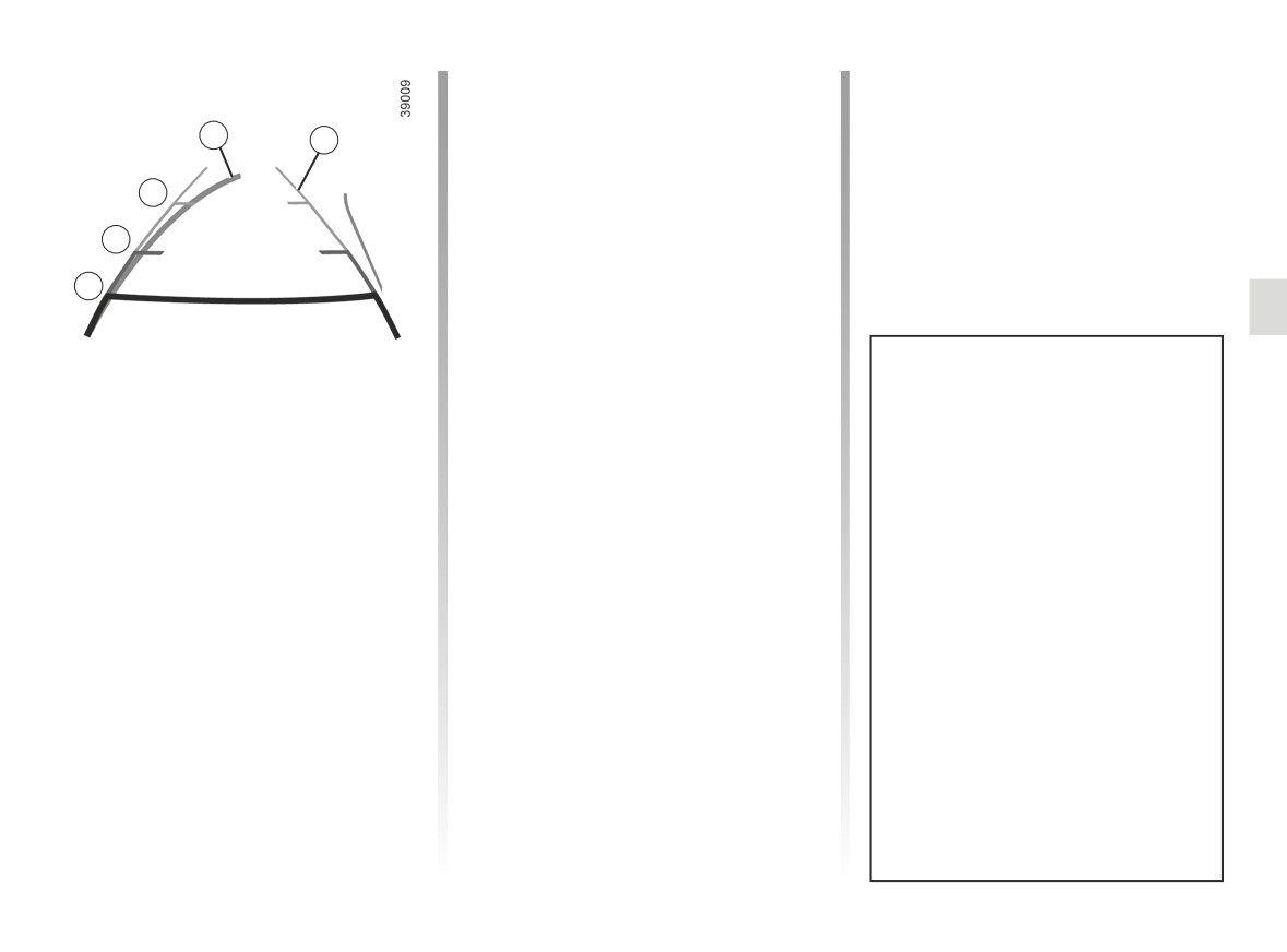
This gauge remains fixed and indicates
the vehicle trajectory if the wheels are
in line with the vehicle.
4
5
This system is initially used with the aid
of several gauges (mobile for trajectory
C
and fixed for distance). When the red
zone is reached, use the bumper image
B
to stop accurately.
A
Special feature
Ensure that the reversing camera is not
obscured (dirt, mud, snow, condensa-
tion, etc.).
The screen shows a reverse image.
Dynamic gauge 4 (depending on the
The frames are a representation
vehicle)
projected on a flat surface. This in-
This is shown in blue on the multime-
formation is to not be taken into ac-
dia screen 3. It indicates the vehicle tra-
count when superimposed on a
jectory according to the position of the
vertical object or an object on the
steering wheel.
ground.
Objects which appear on the edge
Static guide line 5:
of the screen may be deformed.
The fixed clearance gauge comprises
coloured markers A, B and C, indicat-
In very bright light (snow, vehicle in
ing the distance behind the vehicle:
sunshine etc.), the camera vision
may be adversely affected.
- A (red) approximately 30 centime-
tres from the vehicle;
If the rear doors are open or poorly
- B (yellow) approximately 70 centi-
closed, the message “BOOT OPEN”
metres from the vehicle;
appears and, depending on the ve-
- C (green) approximately 150 centi-
hicle, the camera display disap-
metres from the vehicle.
pears.
2.43
CarManuals2.co
REVERSING CAMERA (3/3)
H
F G
D E
K J
D E
F G
H J K
5
5
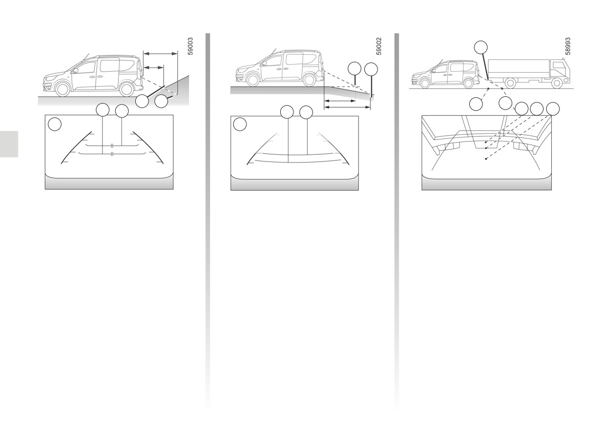
Difference between the
Reversing towards a steep downhill
Reversing towards a protruding
slope
object
estimated distance and
actual distance
The fixed guidelines 5 show the dis-
Position H seems further than position J
tances as further than they actually are.
on the screen. However, position H is at
Reversing towards a steep uphill
the same distance as position K.
Therefore, the objects shown on the
slope
screen are actually closer on the slope.
The trajectory indicated by the fixed
The fixed guidelines 5 show the dis-
and mobile guidelines do not take into
For example, if the screen displays an
tances as closer than they actually are.
account the height of the object. So
object at G, the actual distance of the
there is a risk that the vehicle may col-
The objects shown on the screen are
object is at F.
lide with the object when reversing to-
actually further away on the slope.
wards position K.
For example, if the screen displays an
object at D, the actual distance of the
object is at E.
2.44
CarManuals2.co
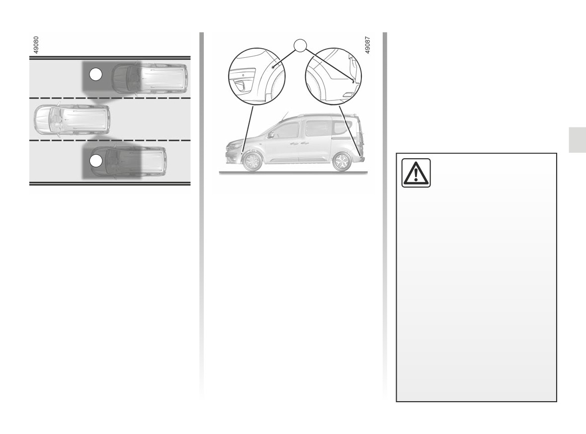
BLIND SPOT WARNING (1/4)
1
A
A
This function is an addi-
tional aid which indicates
other vehicles in the blind
spot area.
This system alerts the driver to other
Special feature
It can never in any case be a subs-
vehicles in the detection zone A.
Make sure that the sensors are not obs-
titute for care nor for the driver’s
The system is activated when the vehi-
cured (by dirt, mud, snow, etc.).
responsibility while in charge of his
cle’s speed is between approximately
If a sensor is obscured, the message
vehicle.
30 km/h
(19 mph) and
140 km/h
“Clean Blind Spot Sensor” will appear
The driver should always be ready
(87 mph).
on the instrument panel. Clean the sen-
for sudden incidents while driv-
sors.
This function uses sensors 1 installed in
ing: always ensure that there are
the front and rear bumper of both sides.
no small, narrow moving obstacles
(such as a child, animal, pushchair,
bicycle, stone, post, etc.) in the blind
spot when manoeuvring.
2.45
CarManuals2.co
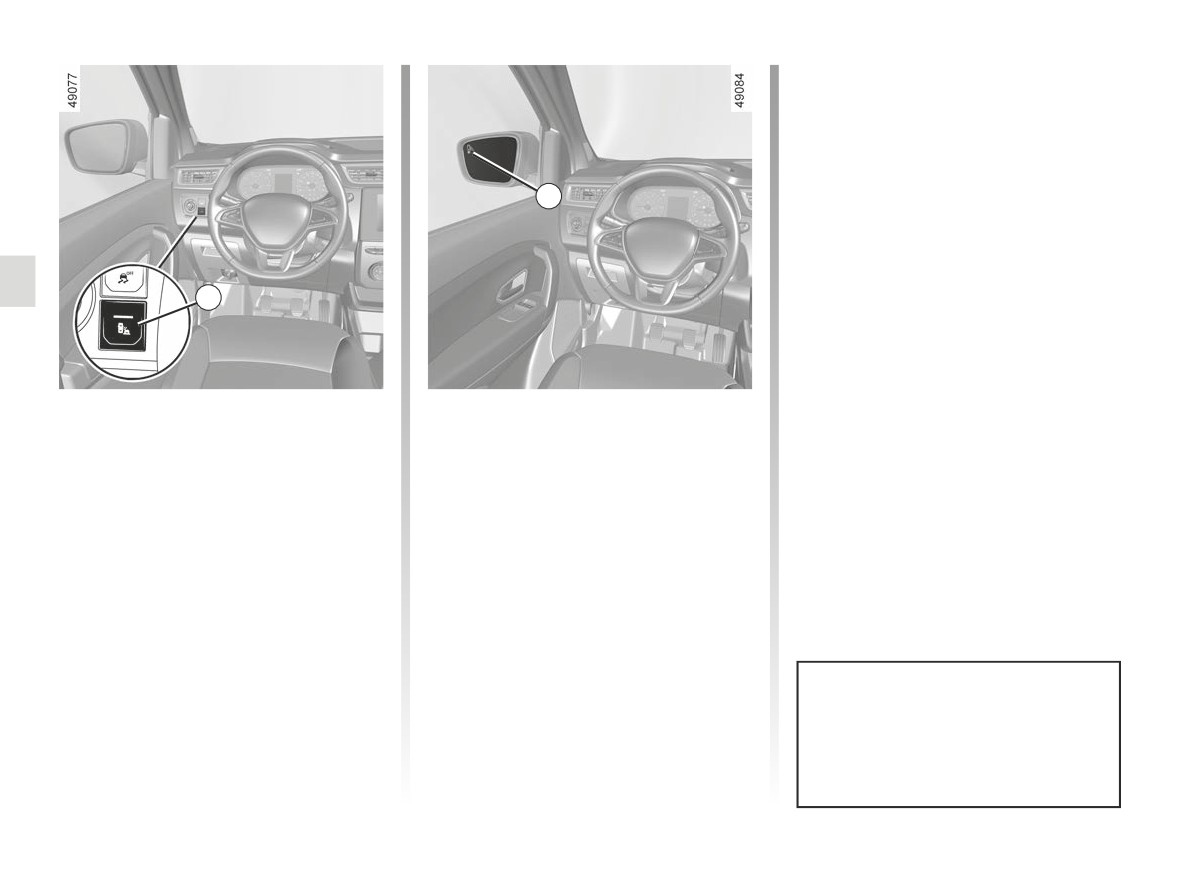
BLIND SPOT WARNING (2/4)
Operation
This function gives a warning:
- when the vehicle speed is between
approximately 19 mph (30 km/h) and
87 mph (140 km/h);
3
- when another vehicle is in the blind
spot area and travelling in the same
direction as your vehicle.
If your vehicle is overtaking another ve-
hicle, the indicator 3 will be activated
2
only if that vehicle remains in the blind
spot for more than one second.
Activation/deactivation
Special condition with trailer
If you press switch 2, the system is ac-
If the vehicle is equipped with a towbar
tivated. The message “Blind spot alert
recognised by the system, the “Trailer:
on” is displayed on the instrument panel
blind spot alert off” message displayed
and the warning light on the switch is il-
on the instrument panel informs you
luminated.
that the function is not operational. The
indicator light in the switch goes out.
If you press the switch 2 again, the
system is deactivated.
For information on the range of equip-
ment adapted to your vehicle, we advise
you to consult an approved Dealer.
When the engine is started, the
system remembers its position
when the ignition was last switched
off.
2.46
CarManuals2.co