Nissan Qashqai (2007-2010). Manual - part 600
 

  Index      Nissan     Nissan Qashqai - service and repair manual 2007 - 2010 year


Search            copyright infringement  


Content   ..  598  599  600  601   ..


Nissan Qashqai (2007-2010). Manual - part 600


OIL PAN

TM-335

< ON-VEHICLE REPAIR >

[CVT: RE0F10A]

C

E

F

G

H

I

J

K

L

M

A

B

TM

N

O

P

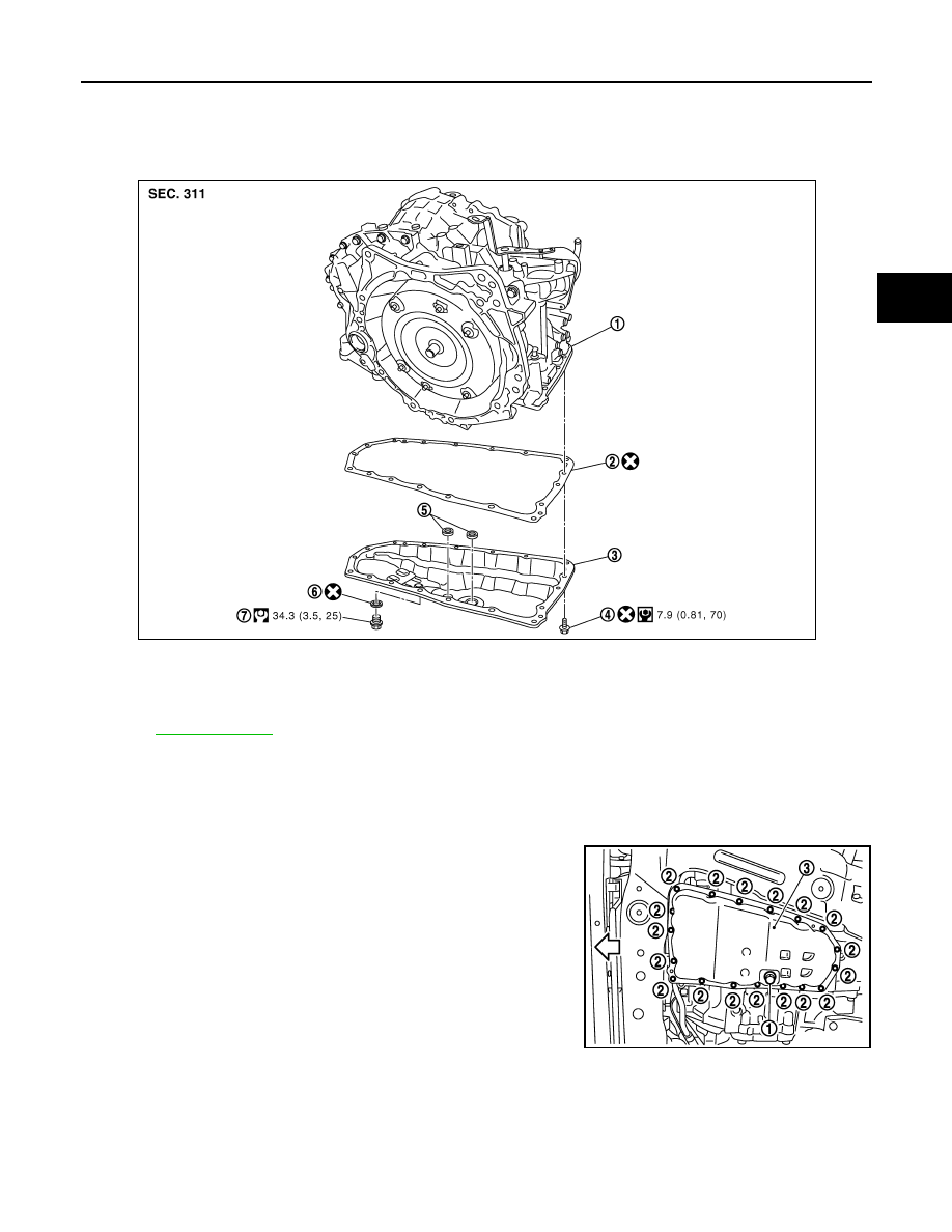
OIL PAN

Exploded View

INFOID:0000000000950755

Removal and Installation

INFOID:0000000000950757

REMOVAL

1.

Remove engine under cover with power tool.

2.

Remove drain plug (1), and then drain CVT fluid from oil pan.

3.

Remove oil pan fitting bolts (2).

4.

Remove oil pan (3).

5.

Remove oil pan gasket from oil pan.

6.

Remove magnet from oil pan.

INSTALLTION

Note the following, and install in the reverse order of removal.

CAUTION:

• Completely remove all moisture, oil and old gasket, etc. from the oil pan gasket mounting surface of

transaxle case and oil pan.

• Never reuse oil pan gasket and oil pan fitting bolts.

1.

Transaxle assembly

2.

Oil pan gasket

3.

Oil pan

4.

Oil pan fitting bolt

5.

Magnet

6.

Drain plug gasket

7.

Drain plug

Refer to 

GI-4, "Components"

 for symbols in the figure.

SCIA7900J

: Vehicle front

JPDIA0072ZZ

TM-336

< ON-VEHICLE REPAIR >

[CVT: RE0F10A]

OIL PAN

Inspection

INFOID:0000000000954882

• Check foreign materials in oil pan to help determine causes of mal-

function. If the CVT fluid is very dark, smells burned, or contains
foreign particles, frictional material (clutches) may need replace-
ment. A tacky film that will not wipe clean indicates varnish build
up. Varnish can cause valves and clutches to stick and can inhibit
pump pressure.

INSPECTION AFTER INSTALLATION

After completing installation, check for CVT fluid leakage and CVT fluid level. Refer to 

TM-314, "Inspection"

.

SCIA3476E

PARK/NEUTRAL POSITION (PNP) SWITCH

TM-337

< ON-VEHICLE REPAIR >

[CVT: RE0F10A]

C

E

F

G

H

I

J

K

L

M

A

B

TM

N

O

P

PARK/NEUTRAL POSITION (PNP) SWITCH

Exploded View

INFOID:0000000000950776

Removal and Installation

INFOID:0000000000950777

REMOVAL

1.

Remove battery. Refer to 

PG-118, "Exploded View"

.

2.

Remove ECM bracket.

3.

Remove PNP switch connector.

4.

Remove control cable. Refer to 

TM-330, "Exploded View"

.

5.

Remove PNP switch from transaxle assembly.

INSTALLATION

Install in the reverse order of removal.

Inspection and Adjustment

INFOID:0000000000950778

ADJUSTMENT OF PNP SWITCH

1.

Move selector lever to “N” position.

2.

Remove control cable from manual lever.

1.

PNP switch

2.

Transaxle assembly

Refer to 

GI-4, "Components"

 for symbols in the figure.

JPDIA0314ZZ

TM-338

< ON-VEHICLE REPAIR >

[CVT: RE0F10A]

PARK/NEUTRAL POSITION (PNP) SWITCH

3.

Loosen mounting bolts (A) of PNP switch. Insert a pin (

φ

4 mm)

into the adjusting holes (B) on both PNP switch and manual
lever for adjusting the position.

4.

Tighten mounting bolts of PNP switch.

5.

Connect control cable on manual lever. Refer to 

TM-324,

"Inspection and Adjustment"

.

ADJUSTMENT AFTER INSTALLATION 

Adjust the CVT positions after installing the control device. Refer to 

TM-324, "Inspection and Adjustment"

.

INSPECTION AFTER INSTALLAION

Check the CVT positions after adjusting the CVT positions. Refer to 

TM-324, "Inspection and Adjustment"

.

SCIA6635J


Content   ..  598  599  600  601   ..