Nissan Qashqai (2007-2010). Manual - part 598
 

  Index      Nissan     Nissan Qashqai - service and repair manual 2007 - 2010 year


Search            copyright infringement  


Content   ..  596  597  598  599   ..


Nissan Qashqai (2007-2010). Manual - part 598


CONTROL DEVICE

TM-327

< ON-VEHICLE REPAIR >

[CVT: RE0F10A]

C

E

F

G

H

I

J

K

L

M

A

B

TM

N

O

P

7.

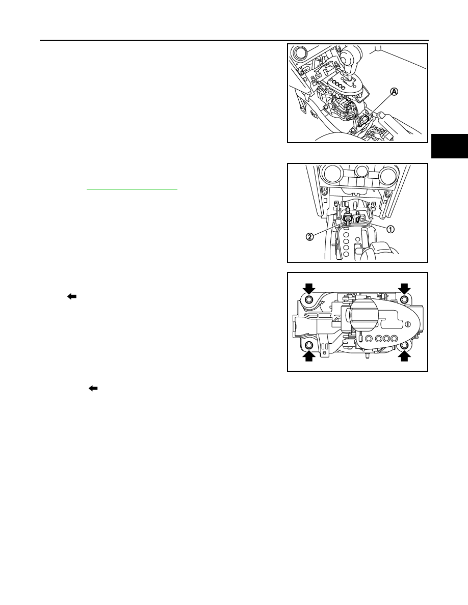
Disconnect CVT device harness connector (A).

8.

Move selector lever to “P” position. 

9.

Disconnect key interlock cable (1) from control device assembly.

10. Disconnect control cable (2) from control device assembly.

Refer to 

TM-330, "Exploded View"

.

11. Remove control device assembly.

12. Remove position lamp.

13. Unhook (

) position indicator plate (1) for removal.

JPDIA0075ZZ

JPDIA0074ZZ

: Bolt

JPDIA0079ZZ

TM-328

< ON-VEHICLE REPAIR >

[CVT: RE0F10A]

CONTROL DEVICE

• LHD

• RHD

INSTALLATION

Note the following, and install in the reverse order of removal.

A

: Driver side

B

: Passenger side

JPDIA0316ZZ

A

: Passenger side

B

: Driver side

JPDIA0317ZZ

CONTROL DEVICE

TM-329

< ON-VEHICLE REPAIR >

[CVT: RE0F10A]

C

E

F

G

H

I

J

K

L

M

A

B

TM

N

O

P

• When installing the control cable (1) to the control device assembly

(2), make sure that the control cable is fully pressed in with the
ribbed (A) surface facing upward.

Inspection and Adjustment

INFOID:0000000000914713

ADJUSTMENT AFTER INSTALLATION

Adjust the CVT positions after installing the control device. Refer to 

TM-324, "Inspection and Adjustment"

.

INSPECTION AFTER INSTALLATION

Check the CVT positions after adjusting the CVT positions. Refer to 

TM-324, "Inspection and Adjustment"

.

JPDIA0078ZZ

TM-330

< ON-VEHICLE REPAIR >

[CVT: RE0F10A]

CONTROL CABLE

CONTROL CABLE

Exploded View

INFOID:0000000000914714

Removal and Installation

INFOID:0000000000914715

REMOVAL

CAUTION:

Make sure that parking brake is applied before removal/installation.

1.

Disconnect control cable from control device assembly. Refer to 

TM-326, "Exploded View"

.

2.

Move selector lever to “P” position.

3.

Remove the air cleaner assembly. Refer to 

EM-144, "Exploded View"

.

4.

Remove nut (A) and control cable (1) from the manual lever (B).

5.

Remove the lock plate (2) and the control cable from the bracket
(3).

6.

Remove exhaust front tube. Refer to 

EX-10, "Exploded View"

.

7.

Separate the propeller shaft. Refer to 

DLN-110, "Exploded View"

(4WD only).

8.

Remove heat plate.

1.

Control cable

2.

Lock plate

3.

Bracket

4.

Transaxle assembly

5.

Bracket

6.

Control device assembly

A.

Manual lever

Refer to 

GI-4, "Components"

 for symbols in the figure.

JPDIA0076GB

JPDIA0106ZZ


Content   ..  596  597  598  599   ..