Nissan Qashqai (2007-2010). Manual - part 515
 

  Index      Nissan     Nissan Qashqai - service and repair manual 2007 - 2010 year


Search            copyright infringement  


Content   ..  513  514  515  516   ..


Nissan Qashqai (2007-2010). Manual - part 515


CSC (CONCENTRIC SLAVE CYLINDER)

CL-15

< REMOVAL AND INSTALLATION >

C

E

F

G

H

I

J

K

L

M

A

B

CL

N

O

P

REMOVAL AND INSTALLATION

CSC (CONCENTRIC SLAVE CYLINDER)

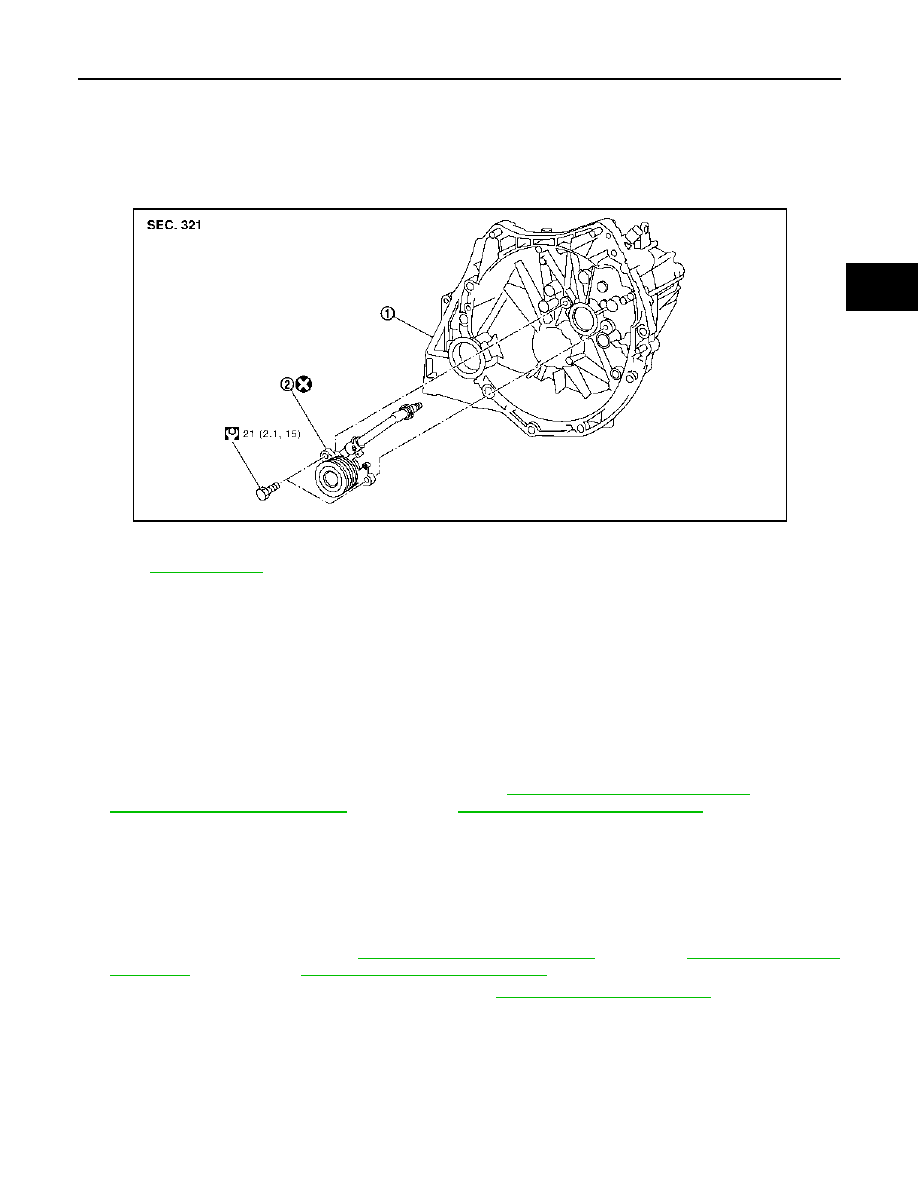
Exploded View

INFOID:0000000001043521

Removal and Installation

INFOID:0000000001043522

CAUTION:

• If transaxle assembly is removed from the vehicle, always replace CSC (Concentric Slave Cylinder).

Return CSC insert to original position to remove transaxle assembly. Dust on clutch disc sliding
parts may damage seal of CSC and may cause clutch fluid leakage.

• Never disassemble CSC.
• Keep painted surface on the body or other parts free of clutch fluid. If it spills, wipe up immediately

and wash the affected area with water.

REMOVAL

1.

Remove transaxle assembly from the vehicle. Refer to 

TM-23, "Removal and Installation"

 (RS5F92R),

TM-69, "Removal and Installation"

 (RS6F94R), or 

TM-123, "Removal and Installation"

 (RS6F52A).

2.

Remove mounting bolts and then remove CSC from clutch housing.

INSTALLATION

1.

Install CSC to clutch housing and then tighten bolts to the specified torque.

CAUTION:

• Never reuse CSC.
• Never insert and operate CSC because piston and stopper of CSC components may fall off.

2.

Install transaxle assembly. Refer to 

TM-23, "Removal and Installation"

 (RS5F92R), 

TM-69, "Removal and

Installation"

 (RS6F94R), or 

TM-123, "Removal and Installation"

 (RS6F52A).

3.

Bleed the air from the clutch hydraulic system. Refer to 

CL-6, "Air Bleeding Procedure"

.

1.

Transaxle assembly

2.

CSC (Concentric Slave Cylinder)

Refer to 

GI-4, "Components"

 for symbols not described on the above.

JPDIB0040GB

CL-16

< REMOVAL AND INSTALLATION >

CLUTCH DISC AND CLUTCH COVER

CLUTCH DISC AND CLUTCH COVER

HR16DE, MR20DE

HR16DE, MR20DE : Exploded View

INFOID:0000000001043523

CAUTION:

• If transaxle assembly is removed from the vehicle, always replace CSC (Concentric Slave Cylinder). Return CSC insert to

original position to remove transaxle assembly. Dust on clutch disc sliding parts may damage seal of CSC and may cause
clutch fluid leakage.

• Never bring any grease to the clutch disc facing, pressure plate surface and flywheel surface.

• When installing, be careful that grease applied to input shaft does not adhere to clutch disc.

• Never clean in solvent on clutch disc.

HR16DE, MR20DE : Removal and Installation

INFOID:0000000001043524

CAUTION:

If transaxle assembly is removed from the vehicle, always replace CSC (Concentric Slave Cylinder).
Return CSC insert to original position to remove transaxle assembly. Dust on clutch disc sliding parts
may damage seal of CSC and may cause clutch fluid leakage.

REMOVAL

1.

Remove transaxle assembly from the vehicle. Refer to 

TM-23, "Removal and Installation"

 (RS5F92R),

TM-69, "Removal and Installation"

 (RS6F94R), or 

TM-123, "Removal and Installation"

 (RS6F52A).

2.

Loosen clutch cover mounting bolts.

3.

Remove clutch cover and clutch disc.

CAUTION:

Never drop clutch disc.

INSTALLATION

1.

Clean clutch disc and input shaft splines to remove grease and powder arisen from abrasion.

2.

Apply recommended grease to clutch disc and input shaft splines.

CAUTION:

1.

Flywheel

2.

Clutch disc

3.

Clutch cover

4.

Input shaft

A. 

First step (MR20DE)

B.

First step (HR16DE)

C.

Final step

 : Apply lithium-based grease including molybdenum disulphide.

Refer to 

GI-4, "Components"

 for symbols not described on the above.

JPDIB0038GB

CLUTCH DISC AND CLUTCH COVER

CL-17

< REMOVAL AND INSTALLATION >

C

E

F

G

H

I

J

K

L

M

A

B

CL

N

O

P

Be sure to apply grease to the points specified. Otherwise, noise, poor disengagement, or damage
to the clutch may result. Excessive grease may cause slip or judder. And if it adheres to seal of
CSC, it cause clutch fluid leakage. Wipe off excess grease. Wipe off any grease oozing from the
parts.

3.

Install clutch disc using a suitable clutch aligner (A).

4.

Install clutch cover. Pre-tighten clutch cover mounting bolts.

5.

Tighten clutch cover mounting bolts evenly to the specified
torque in two steps in the order shown in the figure.

6.

Install transaxle assembly to the vehicle. Refer to 

TM-23,

"Removal and Installation"

 (RS5F92R), 

TM-69, "Removal and

Installation"

 (RS6F94R), or 

TM-123, "Removal and Installation"

(RS6F52A).

HR16DE, MR20DE : Inspection

INFOID:0000000001043525

INSPECTION AFTER REMOVAL

CLUTCH DISC

• Measure circumferential runout relative to clutch disc center spline.

If it is outside the specification, replace clutch disc.

• Measure backlash to clutch disc spline and main drive gear spline

at the circumference of clutch disc. If outside the specification,
replace clutch disc.

• Measure the depth “A” to clutch disc facing rivet heads using cali-

pers. If it exceeds the allowable facing wear limit, replace clutch
disc.

CLUTCH COVER

Check diaphragm spring lever claws for unevenness with the lever
still on the vehicle. If they exceed the tolerance, adjust lever height
using the diaphragm adjusting wrench [SST: ST20050240].

• Check clutch cover thrust ring for wear or breakage. If wear or

breakage is found, replace clutch cover.
NOTE:
• Worn thrust ring will generate a beating noise when tapped at the

rivet with a hammer.

• Broken thrust ring will make a clinking sound when cover is

shaken up and down.

B

: HR16DE

C

:  MR20DE

JPDIB0044ZZ

Runout limit/diameter of the 
area to be measured

: Refer to 

CL-20, 

"Clutch Disc"

.

Maximum allowable spline 
backlash (at outer edge of disc)

: Refer to 

CL-20, 

"Clutch Disc"

.

Facing wear limit (depth to the 
rivet head)

: Refer to 

CL-20, 

"Clutch Disc"

.

SCL221

JPDIB0026ZZ

Tolerance for diaphragm 
spring lever unevenness

: Refer to 

CL-20, 

"Clutch Cover"

.

PCIB0276E

CL-18

< REMOVAL AND INSTALLATION >

CLUTCH DISC AND CLUTCH COVER

• If a trace of burn or discoloration is found on the clutch cover pressure plate to clutch disc contact surface,

repair the surface with sandpaper. If surface is damaged or distorted, replace clutch cover.

K9K

K9K : Exploded View

INFOID:0000000001043557

CAUTION:

• If transaxle assembly is removed from the vehicle, always replace CSC (Concentric Slave Cylinder). Return CSC insert to

original position to remove transaxle assembly. Dust on clutch disc sliding parts may damage seal of CSC and may cause
clutch fluid leakage.

• Never bring any grease to the clutch disc facing, pressure plate surface and flywheel surface.

• When installing, be careful that grease applied to input shaft does not adhere to clutch disc.

• Never clean in solvent on clutch disc.

K9K : Removal and Installation

INFOID:0000000001043558

CAUTION:

If transaxle assembly is removed from the vehicle, always replace CSC (Concentric Slave Cylinder).
Return CSC insert to original position to remove transaxle assembly. Dust on clutch disc sliding parts
may damage seal of CSC and may cause clutch fluid leakage.

REMOVAL

1.

Remove transaxle assembly from the vehicle. Refer to 

TM-69, "Removal and Installation"

.

2.

Loosen clutch cover mounting bolts.

3.

Remove clutch cover and clutch disc.

CAUTION:

Never drop clutch disc.

INSTALLATION

1.

Clean clutch disc and input shaft splines to remove grease and powder arisen from abrasion.

2.

Apply recommended grease to clutch disc and input shaft splines.

CAUTION:

Be sure to apply grease to the points specified. Otherwise, noise, poor disengagement, or damage
to the clutch may result. Excessive grease may cause slip or judder. And if it adheres to seal of

1.

Flywheel

2.

Clutch disc

3.

Clutch cover

4.

Input shaft

 : Apply lithium-based grease including molybdenum disulphide.

Refer to 

GI-4, "Components"

 for symbols not described on the above.

JPDIB0039GB


Content   ..  513  514  515  516   ..