Nissan Qashqai (2007-2010). Manual - part 516
 

  Index      Nissan     Nissan Qashqai - service and repair manual 2007 - 2010 year


Search            copyright infringement  


Content   ..  514  515  516  517   ..


Nissan Qashqai (2007-2010). Manual - part 516


CLUTCH DISC AND CLUTCH COVER

CL-19

< REMOVAL AND INSTALLATION >

C

E

F

G

H

I

J

K

L

M

A

B

CL

N

O

P

CSC, it cause clutch fluid leakage. Wipe off excess grease. Wipe off any grease oozing from the
parts.

3.

Install clutch disc using a suitable clutch aligner (A).

4.

Install clutch cover. Pre-tighten clutch cover mounting bolts.

5.

Tighten clutch cover mounting bolts evenly to the specified
torque in the order shown in the figure.

6.

Install transaxle assembly to the vehicle. Refer to 

TM-69,

"Removal and Installation"

.

K9K : Inspection

INFOID:0000000001043559

INSPECTION AFTER REMOVAL

CLUTCH DISC

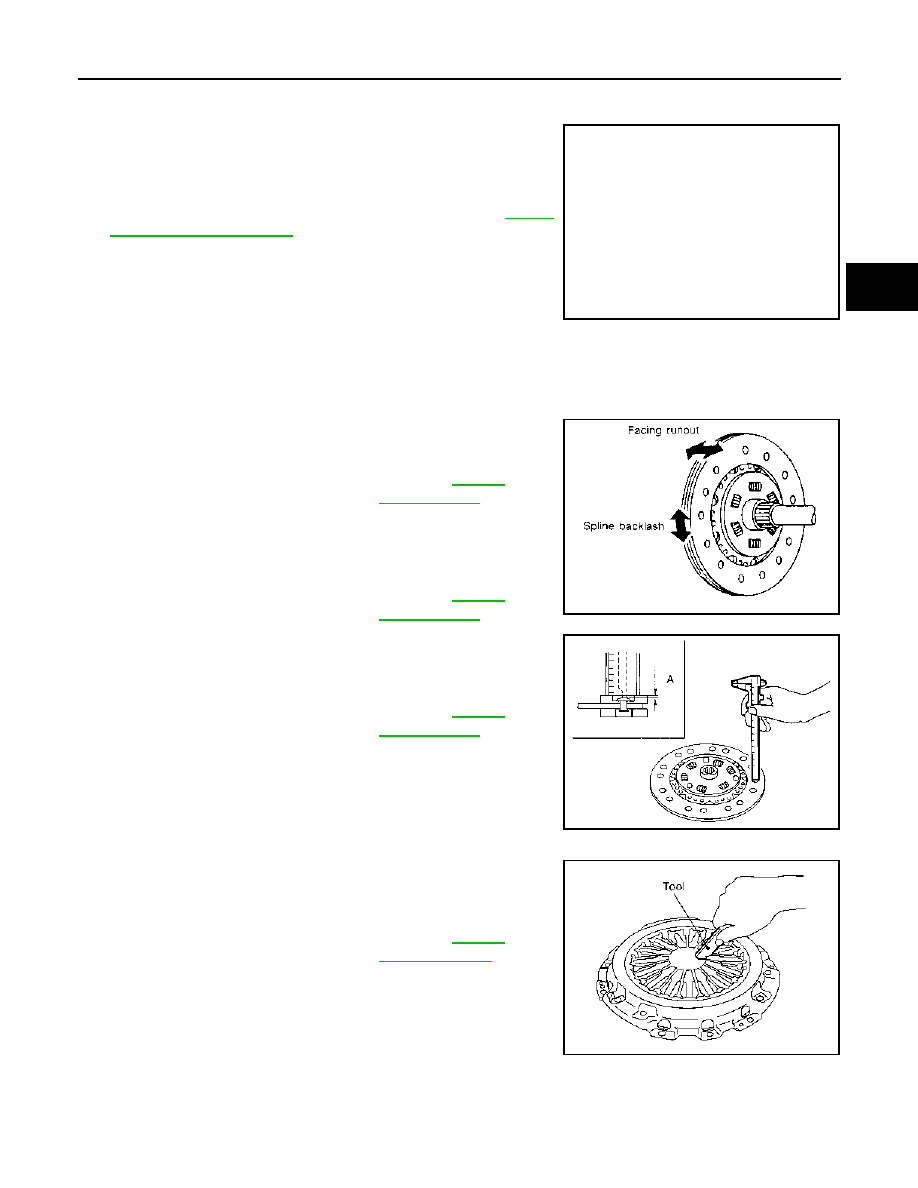
• Measure circumferential runout relative to clutch disc center spline.

If it is outside the specification, replace clutch disc.

• Measure backlash to clutch disc spline and main drive gear spline

at the circumference of clutch disc. If outside the specification,
replace clutch disc.

• Measure the depth “A” to clutch disc facing rivet heads using cali-

pers. If it exceeds the allowable facing wear limit, replace clutch
disc.

CLUTCH COVER

Check diaphragm spring lever claws for unevenness with the lever
still on the vehicle. If they exceed the tolerance, adjust lever height
using the diaphragm adjusting wrench [SST: ST20050240].

• Check clutch cover thrust ring for wear or breakage. If wear or

breakage is found, replace clutch cover.
NOTE:
• Worn thrust ring will generate a beating noise when tapped at the

rivet with a hammer.

• Broken thrust ring will make a clinking sound when cover is

shaken up and down.

• If a trace of burn or discoloration is found on the clutch cover pressure plate to clutch disc contact surface,

repair the surface with sandpaper. If surface is damaged or distorted, replace clutch cover.

PCIB1503E

Runout limit/diameter of the 
area to be measured

: Refer to 

CL-20, 

"Clutch Disc"

.

Maximum allowable spline 
backlash (at outer edge of disc)

: Refer to 

CL-20, 

"Clutch Disc"

.

Facing wear limit (depth to the 
rivet head)

: Refer to 

CL-20, 

"Clutch Disc"

.

SCL221

JPDIB0026ZZ

Tolerance for diaphragm 
spring lever unevenness

: Refer to 

CL-20, 

"Clutch Cover"

.

PCIB0276E

CL-20

< SERVICE DATA AND SPECIFICATIONS (SDS) 

SERVICE DATA AND SPECIFICATIONS (SDS)

SERVICE DATA AND SPECIFICATIONS (SDS)

SERVICE DATA AND SPECIFICATIONS (SDS)

Clutch Control System

INFOID:0000000001043459

Clutch Pedal

INFOID:0000000001043460

Unit: mm (in)

Clutch Disc

INFOID:0000000001043462

Unit: mm (in)

Clutch Cover

INFOID:0000000001043463

Type of clutch control

Hydraulic

Clearance “A” between clutch pedal and ASCD switch threaded 
end while clutch pedal is fully released.

0.74 - 1.96 (0.0291 - 0.0772)

Engine type

HR16DE

MR20DE

K9K

Model

200

225

Facing size (Outer dia. 

×

 Inner dia. 

×


Thickness)

200 

×

 140 

×

 3.5 (7.87 

×

 5.51 

×

 0.138)

225 

×

 160 

×

 3.2 (8.86 

×

 6.30 

×

 0.126)

225 

×

 150 

×

 3.1 (8.86 

×

 5.91 

×

 0.122)

Runout limit/diameter of the area to be 
measured

1.0 (0.039) /200 (7.87) dia.

1.0 (0.039) /215 (8.46) dia.

Maximum allowable spline backlash 
(at outer edge of disc)

0.8 (0.031)

1.0 (0.039)

0.507 (0.0200)

Facing wear limit (depth to the rivet 
head)

0.3 (0.012)

1.0 (0.039)

Engine type

HR16DE

MR20DE

K9K

Transaxle type

RS5F92R

RS6F94R

RS6F52A

RS6F94R

Set-load

4,658 N (475.1 kg, 

1,047.1 lb)

5,390 N (549.8 kg, 1,211.7 lb)

6,300 N (642.6 kg, 

1416.2 lb)

Tolerance for diaphragm 
spring lever unevenness

0.7 mm (0.028 in) or less

1.2 mm (0.047 in) or less

Diaphragm spring lever 
height

29 - 31 mm (1.14 - 1.22 

in)

21 - 23 mm (0.83 -0.91 

in)

31.8 - 33.8 mm (1.252 - 

1.331 in)

TM-1

TRANSMISSION & DRIVELINE

C

E

F

G

H

I

J

K

L

M

SECTION 

TM

A

B

TM

N

O

P

CONTENTS

TRANSAXLE & TRANSMISSION

5MT: RS5F92R

FUNCTION DIAGNOSIS ...............................

8

M/T SYSTEM  .......................................................

8

System Diagram ........................................................

8

System Description  ...................................................

8

COMPONENT DIAGNOSIS  .........................

10

POSITION SWITCH ............................................

10

BACK-UP LAMP SWITCH  ........................................

10

BACK-UP LAMP SWITCH : Component Parts Lo-
cation .......................................................................

10

BACK-UP LAMP SWITCH : Component Inspec-
tion ..........................................................................

10

PARK/NEUTRAL POSITION (PNP) SWITCH ...........

10

PARK/NEUTRAL POSITION (PNP) SWITCH : 
Component Parts Location ......................................

10

PARK/NEUTRAL POSITION (PNP) SWITCH : 
Component Inspection  ............................................

10

SYMPTOM DIAGNOSIS  ..............................

12

NOISE, VIBRATION AND HARSHNESS 
(NVH) TROUBLESHOOTING  ............................

12

NVH Troubleshooting Chart  ....................................

12

PRECAUTION ..............................................

13

PRECAUTIONS ..................................................

13

Service Notice or Precautions for Manual Tran-
saxle ........................................................................

13

PREPARATION ...........................................

14

PREPARATION ..................................................

14

Special Service Tools ............................................

14

Commercial Service Tools .....................................

15

ON-VEHICLE MAINTENANCE ....................

17

GEAR OIL  .........................................................

17

Exploded View .........................................................

17

Draining ...................................................................

17

Refilling ....................................................................

17

Inspection ................................................................

17

ON-VEHICLE REPAIR .................................

18

SIDE OIL SEAL .................................................

18

Exploded View .........................................................

18

Removal and Installation  .........................................

18

CONTROL LINKAGE ........................................

19

Exploded View .........................................................

19

Removal and Installation  .........................................

19

Inspection ................................................................

21

AIR BREATHER HOSE  ....................................

22

Exploded View .........................................................

22

Removal and Installation  .........................................

22

REMOVAL AND INSTALLATION  ...............

23

TRANSAXLE ASSEMBLY ................................

23

Exploded View .........................................................

23

Removal and Installation  .........................................

23

DISASSEMBLY AND ASSEMBLY ..............

25

TRANSAXLE ASSEMBLY ................................

25

Exploded View .........................................................

25

Disassembly ............................................................

29

Assembly .................................................................

34

Adjustment ...............................................................

39

INPUT SHAFT AND GEAR ...............................

41

Exploded View .........................................................

41

Disassembly ............................................................

41

Assembly .................................................................

41

Inspection ................................................................

41

MAINSHAFT AND GEAR  .................................

43

Exploded View .........................................................

43

TM-2

Disassembly ...........................................................

43

Assembly ................................................................

43

Inspection ...............................................................

44

REVERSE IDLER SHAFT AND GEAR  .............

46

Exploded View  ........................................................

46

Disassembly ...........................................................

46

Assembly ................................................................

46

FINAL DRIVE  .....................................................

47

Exploded View  ........................................................

47

Disassembly ...........................................................

47

Assembly ................................................................

47

Inspection ...............................................................

47

SHIFT FORK AND FORK ROD  .........................

49

Exploded View  ........................................................

49

Disassembly ...........................................................

49

Assembly ................................................................

49

Inspection ...............................................................

49

SERVICE DATA AND SPECIFICATIONS 
(SDS) ...........................................................

50

SERVICE DATA AND SPECIFICATIONS 
(SDS) ..................................................................

50

General Specification  .............................................

50

6MT: RS6F94R

FUNCTION DIAGNOSIS  .............................

52

M/T SYSTEM  .....................................................

52

System Diagram  .....................................................

52

System Description .................................................

52

COMPONENT DIAGNOSIS  ........................

54

POSITION SWITCH  ...........................................

54

BACK-UP LAMP SWITCH ........................................

54

BACK-UP LAMP SWITCH : Component Parts Lo-
cation .....................................................................
.

54

BACK-UP LAMP SWITCH : Component Inspec-
tion .........................................................................
.

54

PARK/NEUTRAL POSITION (PNP) SWITCH  ..........

54

PARK/NEUTRAL POSITION (PNP) SWITCH : 
Component Parts Location  ....................................
.

54

PARK/NEUTRAL POSITION (PNP) SWITCH : 
Component Inspection ...........................................
.

54

SYMPTOM DIAGNOSIS  .............................

56

NOISE, VIBRATION AND HARSHNESS 
(NVH) TROUBLESHOOTING  ............................

56

NVH Troubleshooting Chart  ...................................

56

PRECAUTION .............................................

57

PRECAUTIONS  .................................................

57

Service Notice or Precautions for Manual Tran-
saxle ......................................................................
.

57

PREPARATION ..........................................

58

PREPARATION .................................................

58

Special Service Tools ............................................

58

Commercial Service Tools ....................................

59

ON-VEHICLE MAINTENANCE ..................

61

GEAR OIL ..........................................................

61

Exploded View  ........................................................

61

Draining ...................................................................

61

Refilling ...................................................................

61

Inspection ................................................................

61

ON-VEHICLE REPAIR  ...............................

62

SIDE OIL SEAL  .................................................

62

Exploded View  ........................................................

62

Removal and Installation .........................................

62

CONTROL LINKAGE  ........................................

63

Exploded View  ........................................................

63

Removal and Installation .........................................

63

Inspection ................................................................

66

AIR BREATHER HOSE .....................................

67

Exploded View  ........................................................

67

Removal and Installation .........................................

67

REMOVAL AND INSTALLATION ..............

68

TRANSAXLE ASSEMBLY  ................................

68

Exploded View  ........................................................

68

Removal and Installation .........................................

69

DISASSEMBLY AND ASSEMBLY ............

71

TRANSAXLE ASSEMBLY  ................................

71

Exploded View  ........................................................

71

Disassembly ............................................................

76

Assembly ................................................................

82

INPUT SHAFT AND GEAR  ...............................

88

Exploded View  ........................................................

88

Disassembly ............................................................

88

Assembly ................................................................

89

Inspection ................................................................

90

MAINSHAFT AND GEAR  ..................................

92

Exploded View  ........................................................

92

Disassembly ............................................................

92

Assembly ................................................................

93

Inspection ................................................................

95

REVERSE IDLER SHAFT AND GEAR  .............

97

Exploded View  ........................................................

97

Disassembly ............................................................

97

Assembly ................................................................

98

FINAL DRIVE .....................................................

99

Exploded View  ........................................................

99

Disassembly ............................................................

99


Content   ..  514  515  516  517   ..