Harley Davidson 1999-2005 Harley Dyna Models. Repair Manual - page 9
-------------------------------------------------------------------------------------------------------------------------------------------------------------
160
CHAPTER FOUR
20. If necessary, disassemble and remove the cam-
shafts as described in this chapter.
214
Installation
NOTE
It is necessary to release the second-
ary chain tension in order to install
the camshaft inner ends into the
crankcase bearings (D, Figure 213).
If the tension is not released, the inner
ends of the camshafts are pulled to-
gether and out of alignment with the
bearings, making installation difficult
if not impossible.
215
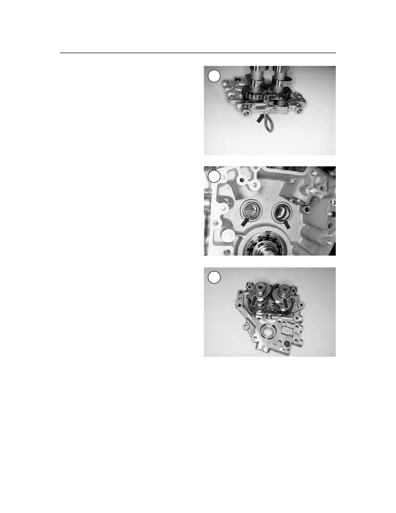
1. Release the tension on the camshaft secondary
chain tension as follows:
a. Install the camshaft chain tensioner tool
onto the camshaft secondary chain
tensioner.
b. Using a wrench, rotate the tool counterclock-
wise and insert the hold pin (Figure 214)
through the hole in the outer surface of the
support plate and into the hole in the
tensioner. Push the hold pin all the way in un-
til it bottoms.
c. Remove the wrench and tensioner tool from
216
the tensioner.
2. Push on the oil pump assembly to make sure it is
correctly seated against the crankcase.
3. Install a new O-ring (A, Figure 213) onto the oil
pump assembly and a new O-ring (B) onto the lower
location. Apply a light coat of clean engine oil to the
O-rings.
4. On 2000-on models, install a new upper O-ring
(C, Figure 213). Apply a light coat of clean engine
oil to the O-ring.
5. Lubricate the camshaft needle bearing (Figure
215) in the crankcase and the camshaft bearing sur-
During
installation,
the
camshaft
faces (Figure 216) with clean engine oil.
ends may not be correctly aligned
6. If the camshafts were removed from the support
with the needle bearings. If force is
plate, check that the timing mark (Figure 217) on
applied, the needle bearing(s) will
each camshaft is aligned with each other. If not, re-
be damaged.
position the camshafts prior to installing the assem-
bly into the crankcase.
8.
Slowly install the camshaft support plate
as-
7. If removed, install the two locating dowels (E,
sembly into the crankcase. Guide the camshaft
Figure 213) onto the crankcase.
ends into the crankcase needle bearings. If neces-
CAUTION
sary, slightly rotate and/or wiggle the end of the
Do not force the camshaft support
rear cylinder camshaft (Figure 218) to assist in the
plate assembly into the crankcase.
alignment.