Harley Davidson 1999-2005 Harley Dyna Models. Repair Manual - page 10
-------------------------------------------------------------------------------------------------------------------------------------------------------------
180
CHAPTER FOUR
295
296
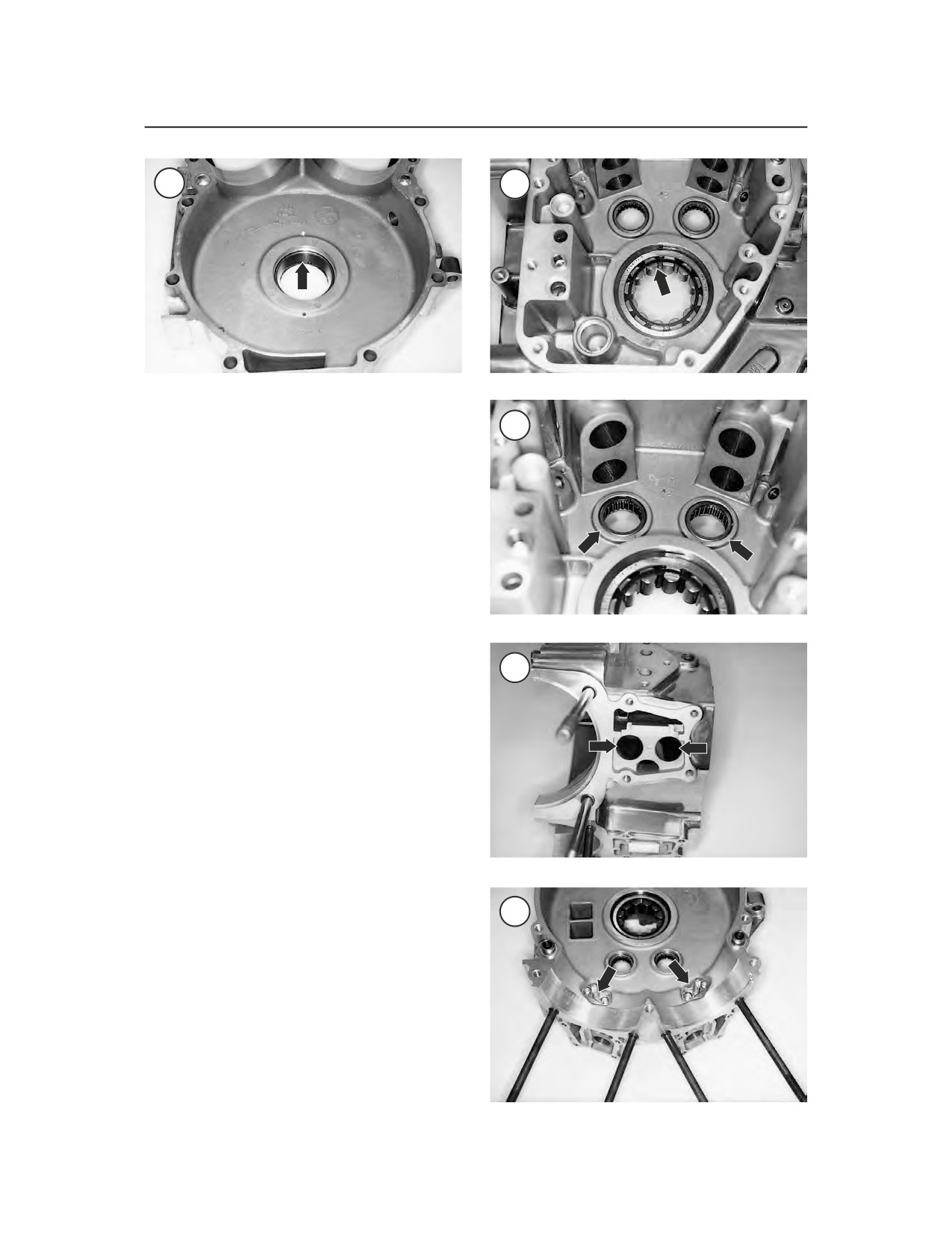
295 for the inner bearing race. Also, check the roller
bearings for wear or damage. The bearings must
297
turn smoothly with no roughness. If any of these
parts are worn, replace the bearing assembly as de-
scribed under Left Side Main Bearing Assembly Re-
placement in this chapter.
6. Inspect the right side main needle bearing (Fig-
ure 296) for wear or damage. The bearing must
turn smoothly with no roughness. If damaged, re-
place the bearing assembly as described under
Right Side Main Bearing Replacement in this
chapter.
7. Inspect the camshaft needle bearings (Figure
297) in the right side crankcase for damage. To re-
place this bearing, refer to Camshaft Support Plate
298
in this chapter.
8. Inspect the valve lifter bore receptacles (Figure
298) for wear or damage. Refer to Valve Lifters in
this chapter.
NOTE
If the original piston cooling jets are
being reinstalled, apply Loctite No.
222
(purple) or an equivalent
threadlocking compound to the screw
threads prior to installation.
9. Make sure the piston cooling jets (Figure 299)
299
are clear. If necessary, remove the T20 Torx mount-
ing screws, remove the cooling jets and O-rings.
Clean the oil jets with compressed air. Install new
O-rings and tighten the screws securely.
Crankshaft and Connecting Rods
Cleaning and Inspection
If any portion of the crankshaft and/or connecting
rods are worn or damaged, they must be replaced as