Harley Davidson 2008 Touring Models. Electrical Diagnostics Manual - page 15
HOME
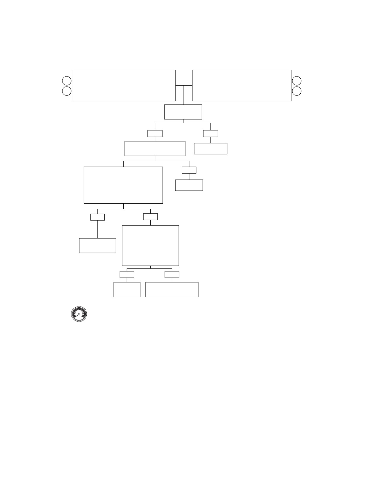
Fuel Injectors: DTC P0261, P0262, P0263, P0264 (Part 2 of 3)
Continued from Fuel Injectors: DTC P0261, P0262,
Continued from Fuel Injectors: DTC P0261, P0262,
P0263, P0264 (Part 1 of 3).
P0263, P0264 (Part 1 of 3).
3
3
FRONT INJECTOR: DTC P0261 or P0262.
REAR INJECTOR: DTC P0263 or P0264.
Measure resistance between Breakout Box terminal
Measure resistance between Breakout Box terminal
4
4
“28” (W/Y) wire and terminal “B” of front injector
“23” (GN/GY) wire and terminal “B” of rear injector
connector [84B].
connector [85B].
Resistance
less than 0.5 ohm?
YES
NO
Check for continuity between
Reconnect.
Terminal “73” and ground.
Front injector codes: Check continuity
NO
between terminal “28” and terminal “73”.
or
Rear injector codes: Check continuity
Repair open
between Terminal “23” and Terminal “73".
Continuity present?
YES
NO
Check for voltage with key on.
Front injector codes: Check
Breakout Box terminal “28”.
Repair short
Rear injector codes: Check
to ground.
Breakout Box terminal “23”.
Voltage present after 2
seconds?
YES
NO
Repair short
Replace ECM. Reprogram
to voltage.
and learn password.
fc01042_en
Clear codes using speedometer self diagnostics. See
4.6 SPEEDOMETER SELF DIAGNOSTICS.
Confirm proper operation with no check engine lamp.
4-106 2008 Touring Diagnostics: Engine Management
HOME
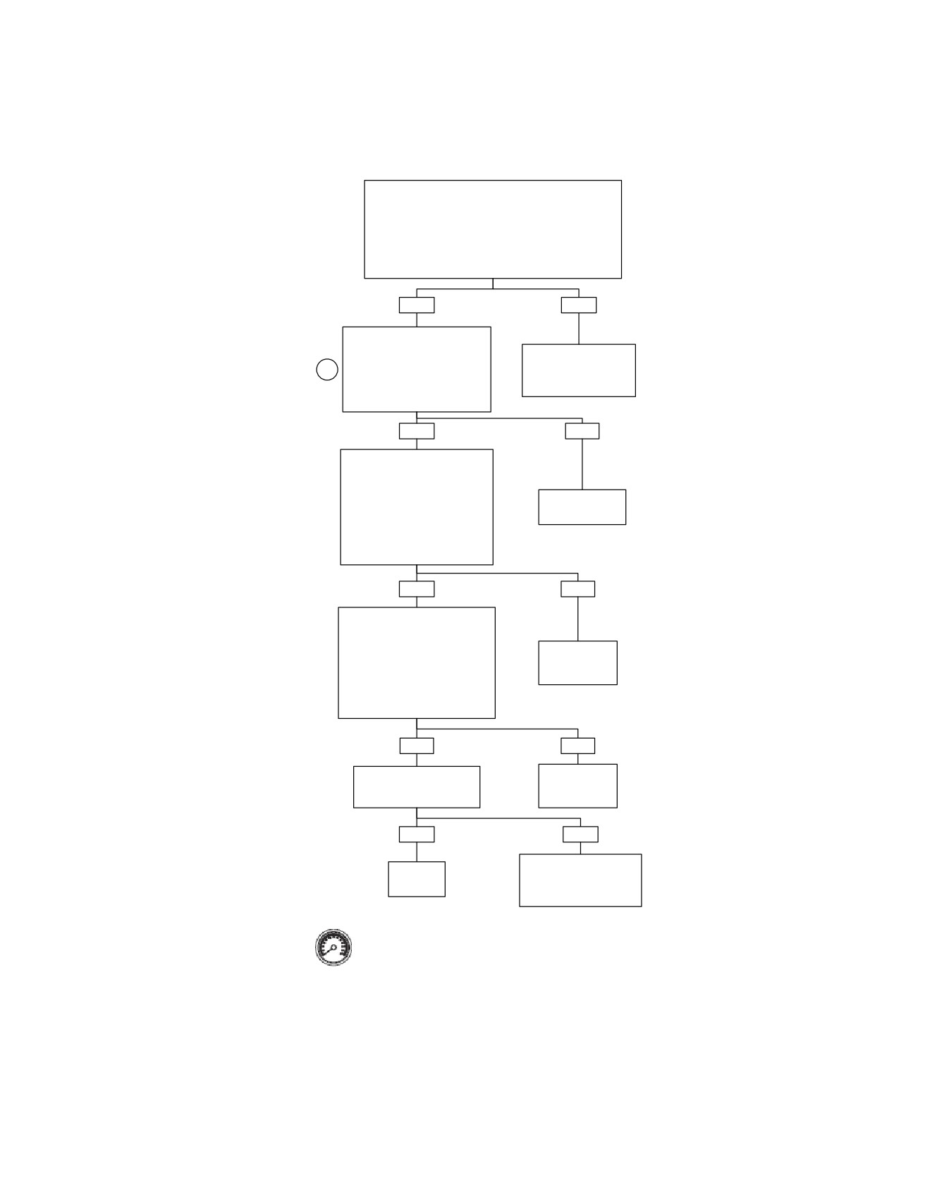
Fuel Injectors: DTC P0261, P0262, P0263, P0264 (Part 3 of 3)
Continued from Fuel Injectors: DTC P0261, P0262,
P0263, P0264 (Part 1 of 3).
Check for 12 volts at terminal “30” of the System Relay.
Correct voltage present?
NOTE:
Depending on relay used relay socket terminal could be
shown as “3” or “3D”.
YES
NO
Check for 12 volts at terminal
“86” of the System Relay.
Find and repair open on
Correct voltage present?
(BE/GY) wire between
4
NOTE:
System Fuse and
Depending on relay used relay
System Relay.
socket terminal could be shown
as “1” or “4D”.
YES
NO
Measure resistance between
terminal “86” of the System
Relay and ECM terminal “73” on
Breakout Box.
See 4.11 NO
Resistance less than 0.5 ohm?
ECM POWER.
NOTE:
Depending on relay used relay
socket terminal could be shown
as “1” or “4D”.
YES
NO
Measure resistance between
terminal “85” of the System Relay
and ECM terminal “27” on
Breakout Box.
Find and repair
Resistance less than 0.5 ohm?
open on (W/BK)
NOTE:
wire.
Depending on relay used relay
socket terminal could be shown as
“2” or “3C”.
YES
NO
Install known good relay.
Find and repair
Does Fuel Pump run for first
open on (GN/O)
2 seconds after IGNITION?
wire.
YES
NO
Reinstall original System
Replace
Relay. Replace ECM.
System
Reprogram and learn
Relay.
password.
Clear codes using speedometer self
fc01043_en
diagnostics. See 4.6 SPEEDOMETER
SELF DIAGNOSTICS. Confirm proper
operation with no check engine lamp.
2008 Touring Diagnostics: Engine Management 4-107
HOME
DTC P0373,
P0374
4.23
GENERAL
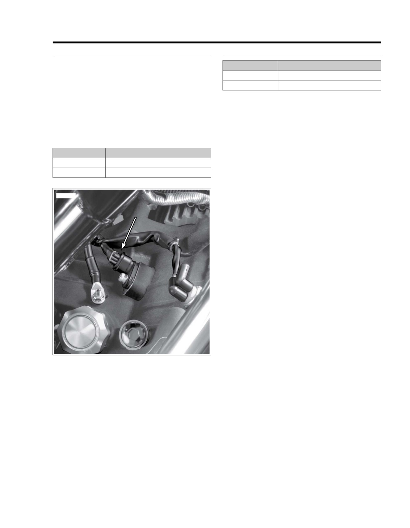
ed01265
CKP Sensor
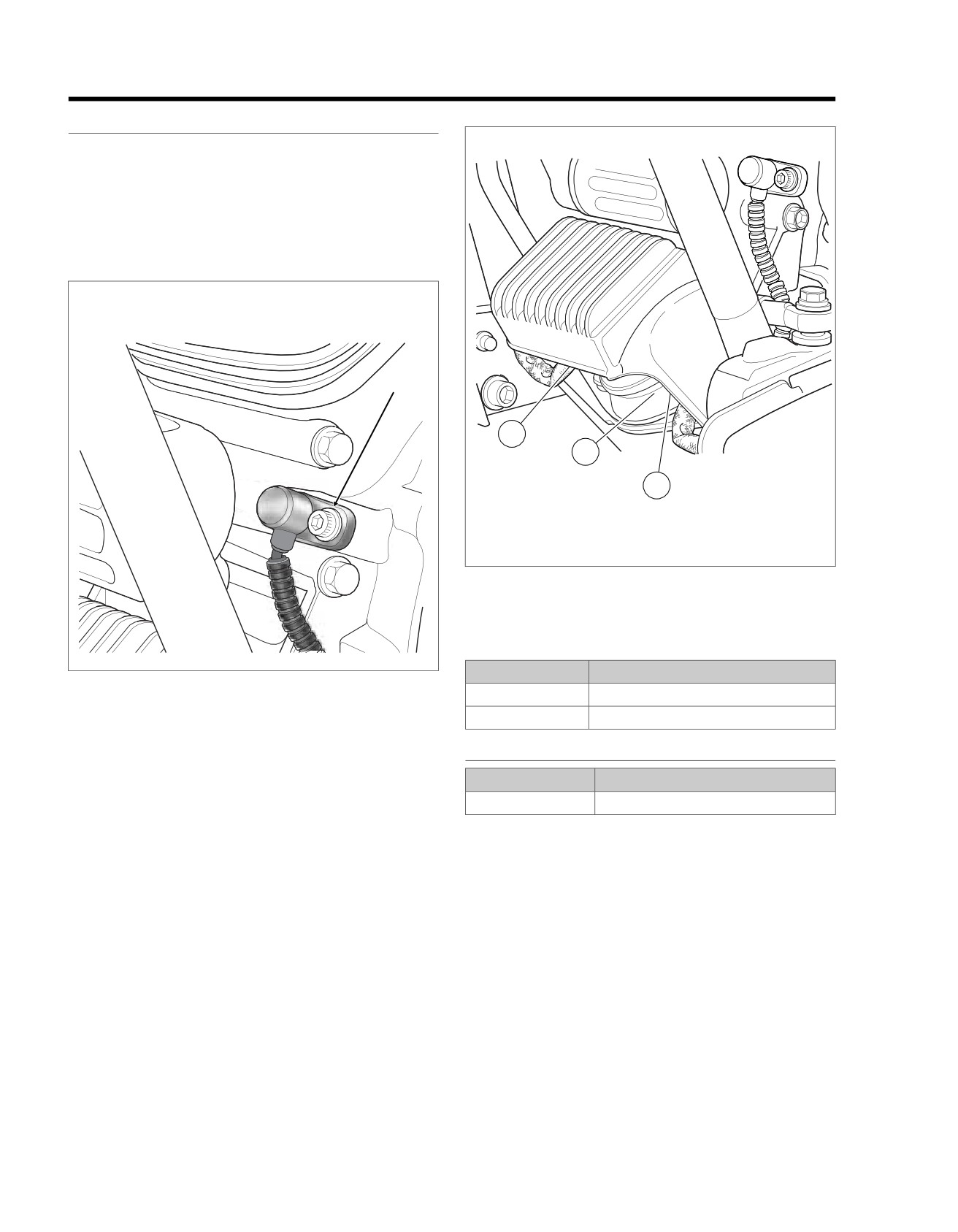
If the CKP sensor signal is weak or absent, Diagnostic Trouble
Code (DTC) P0373 or P0374 will be set.
NOTE
If signal is not detected or cannot synchronize (DTC P0374),
engine will not start.
ed02061
1
2
3
1. Voltage Regulator [77]
2. CKP Sensor [79]
3. Stator [47]
Figure 4-48. Voltage Regulator (Left Side View)
Table 4-38. Code Description
DTC
DESCRIPTION
Figure 4-47. CKP Sensor
P0373
CKP sensor intermittent
P0374
CKP sensor synch error
DIAGNOSTICS
PART NUMBER
TOOL NAME
HD-41404-B
HARNESS CONNECTOR TEST KIT
Diagnostic Tips
•
Engine must be cranked for more than five seconds
without CKP sensor signal to set a DTC.
Diagnostic Notes
Each reference number below correlates to a circled number
on the flow chart(s).
1. Connect BREAKOUT BOX (Part No. HD-48637) to ECM
wire harness only
(leave ECM disconnected). See
4.7 BREAKOUT BOX: EFI.
2. One megohm is very high resistance. Some meters will
read OL, etc.
3. Use HARNESS CONNECTOR TEST KIT (Part No. HD-
41404-B), brown socket probes and patch cords.
4-108 2008 Touring Diagnostics: Engine Management
HOME
4. For testing purposes, install sensor without running wiring
if system is now OK.
along normal path. Disconnect and route wiring properly
em00102
Electronic Control Module
[78A]
[78B]
Crank Position
Sensor
(CKP)
[79A]
1
2
1
2
[79B]
Crank position sensor
43
43
BK
Crank position sensor (+)
63
63
R
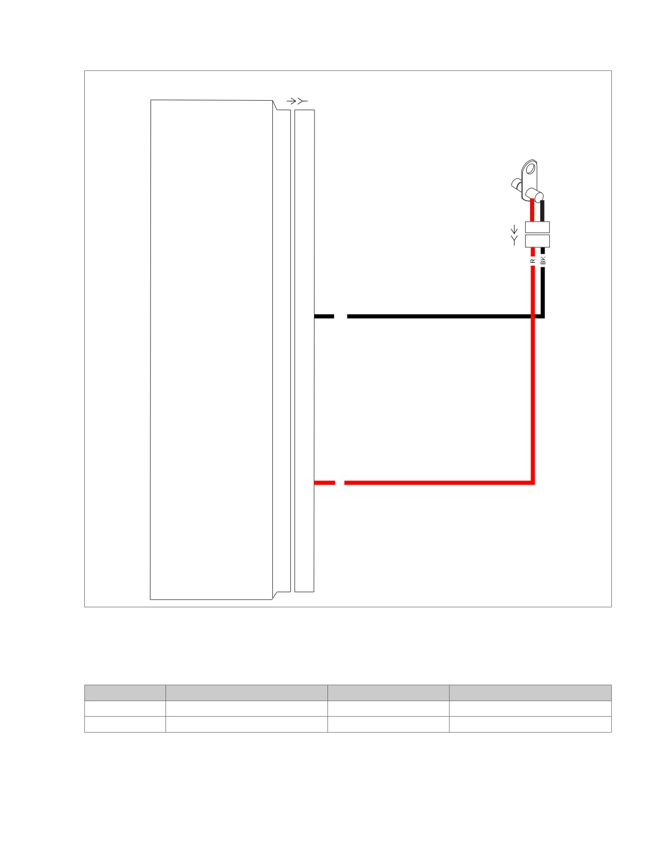
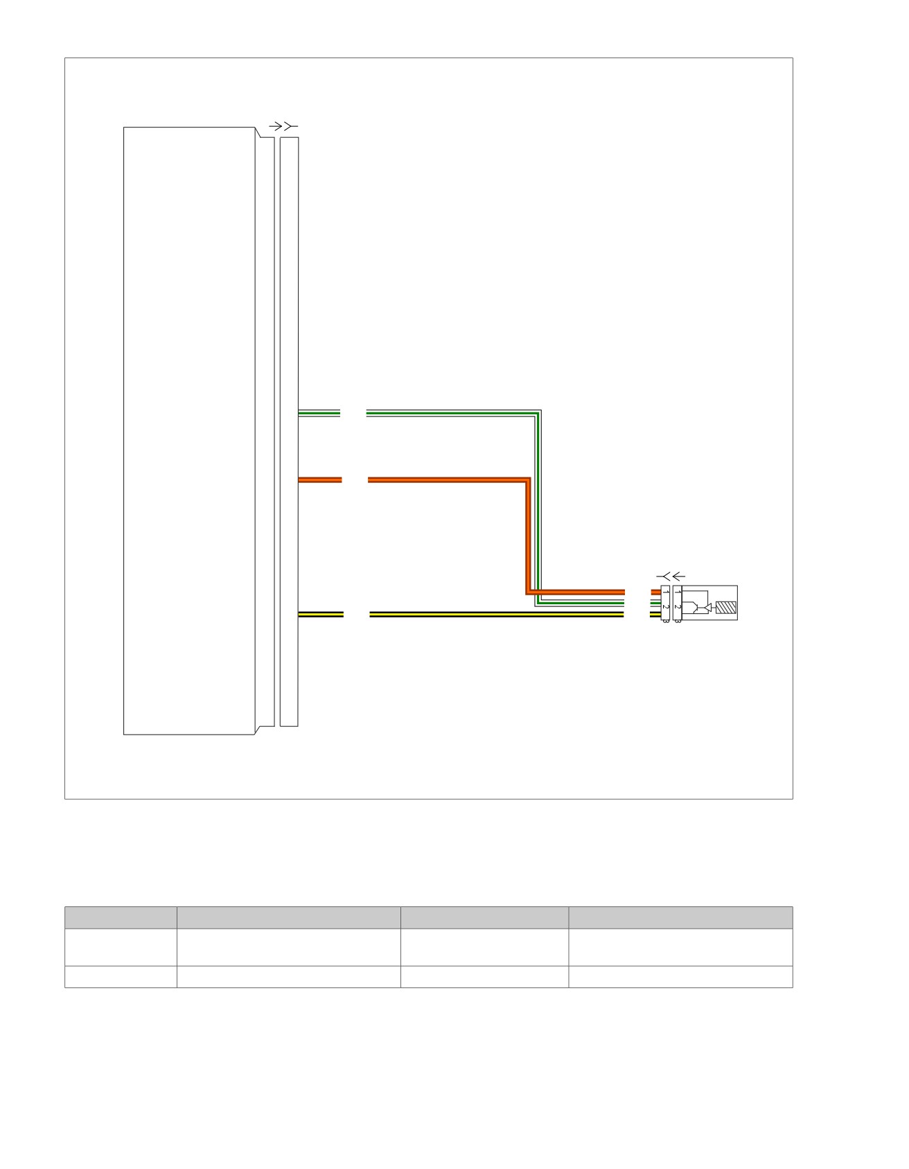
Figure 4-49. CKP Sensor Circuit
Table 4-39. Wire Harness Connectors
NO.
DESCRIPTION
TYPE
LOCATION
[78]
Electronic Control Module (ECM)
73-place Delphi
Under seat
[79]
Crankshaft Position (CKP) Sensor
2-place Mini-Deutsch
Bottom of voltage regulator
2008 Touring Diagnostics: Engine Management 4-109
HOME
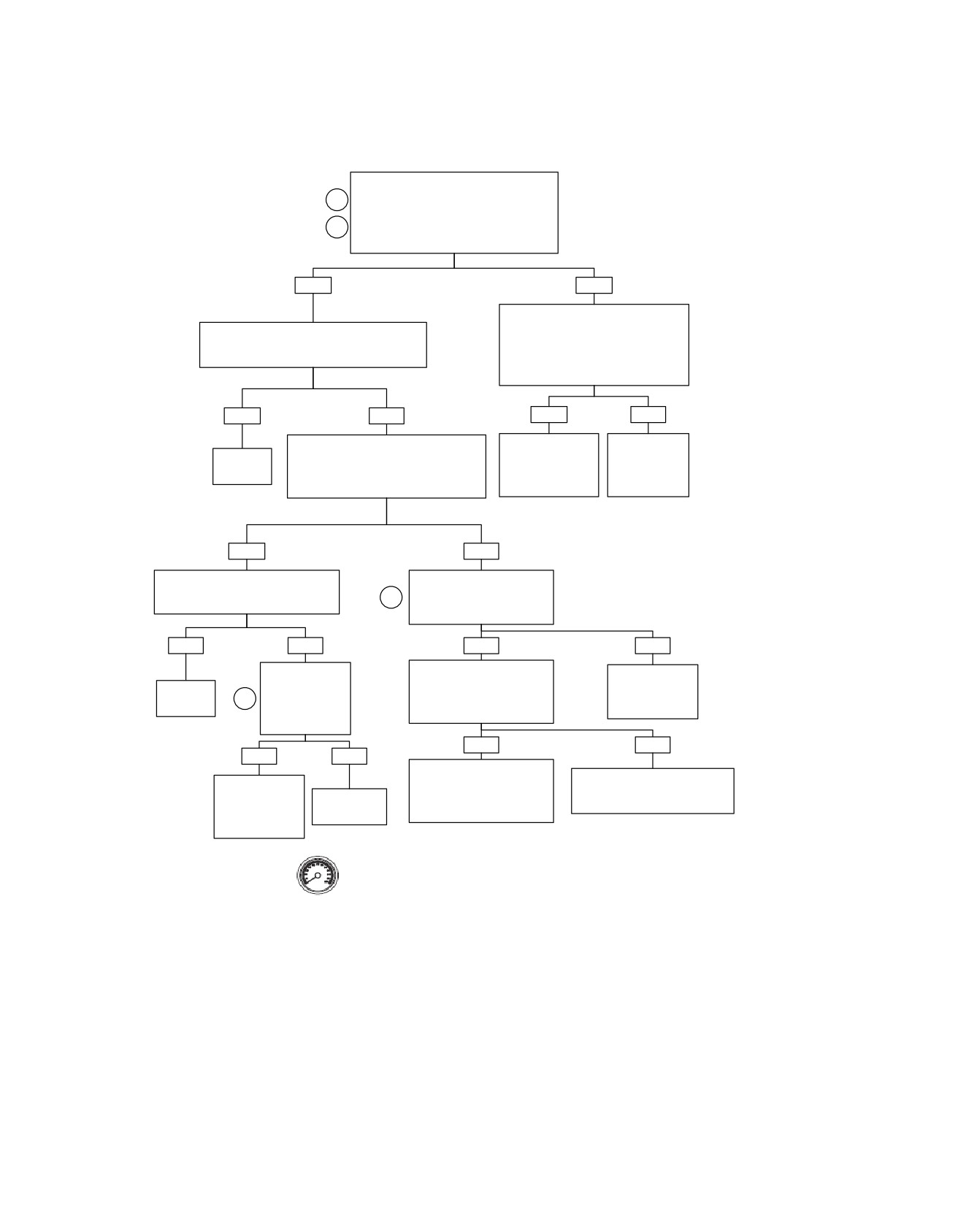
CKP Sensor: DTC P0373, P0374
Connect Breakout Box to harness only,
leaving ECM disconnected. Measure
1
resistance between terminals “63” and “73”
and between terminals “43” and “73” on
2
Breakout Box.
Resistance more than 1 megohm?
YES
NO
Disconnect connector [79]. Leaving
ECM disconnected, measure resistance
Check for intermittent connection, pinched or
between terminals “43” and “73” and
damaged wires, and loose CKP Sensor fasteners.
terminals “63” and “73” on Breakout Box.
Conditions found?
Continuity to ground (less than 1
megohm resistance)?
YES
NO
YES
NO
Connect DVOM to terminals “43” and “63”
Repair short to
Replace
on Breakout Box.
ground on (R) or
CKP Sensor.
Repair as
Set DVOM to AC volts and crank engine.
(BK) wire between
See Touring
necessary.
Does DVOM read 1.0 VAC minimum
connectors [78B]
Service
during cranking?
and [79B].
Manual.
YES
NO
With DVOM still connected, check for
Connect DVOM at terminals
intermittents using 4.8 WIGGLE TEST.
“1” and “2” of connector [79A].
3
Intermittents present?
Does DVOM read 1.0 VAC
minimum while cranking?
YES
NO
YES
NO
Install known
Check for continuity between
Replace CKP
good CKP Sensor.
terminal “1” of connector [79B]
Sensor.
Repair as
Clear codes and
and Terminal “63” on Breakout
4
See Touring
necessary.
retest.
Box.
Service Manual.
Did DTC P0373 or
Continuity present?
P0374 reset?
YES
NO
YES
NO
Repair open on (BK) wire
Repair open on (R) wire between
Reinstall original
between terminal “2” of
terminal “1” of connector [79B] and
CKP Sensor.
connector [79B] and terminal
Replace CKP
terminal “63” of connector [78B].
Replace ECM.
“43” of connector [78B].
Sensor
Reprogram and
learn password.
Clear codes using speedometer self diagnostics.
See 4.6 SPEEDOMETER SELF DIAGNOSTICS.
fc01044_en
Confirm proper operation with no check engine lamp.
4-110 2008 Touring Diagnostics: Engine Management
HOME
DTC P0444,
P0445
4.24
or low vehicle speed. Power for the purge solenoid is supplied
GENERAL
by the system relay. The system relay also provides power for
Purge Solenoid (CA and Select Foreign
the VSS, fuel pump and the ignition coil. The ECM provides a
path to ground to trigger the purge solenoid.
Market Models Only)
NOTES
See Figure 4-50. To comply with California Emissions, a purge
solenoid is mounted beneath the fuel tank of the vehicle, con-
•
System fuse and system relay failures or wiring harness
necting to the vent line in the top of the fuel tank and to a vent
problems will cause 12V power to be lost to the VSS,
canister mounted on the vehicle chassis under the battery
ignition coils, fuel pump and purge solenoid.
holding tray. A return line from the canister reconnects to the
•
Purge solenoid is not installed on non-California vehicles
air intake manifold allowing vented fumes to be recirculated,
and DTCs P0444 and P0445 are not available. If these
for emission efficiency.
DTCs appear, the ECM is improperly programmed and
The purge solenoid is timed to the throttle position and is dis-
should be reprogrammed.
abled during startup, low engine temperature, low engine speed
ed01290
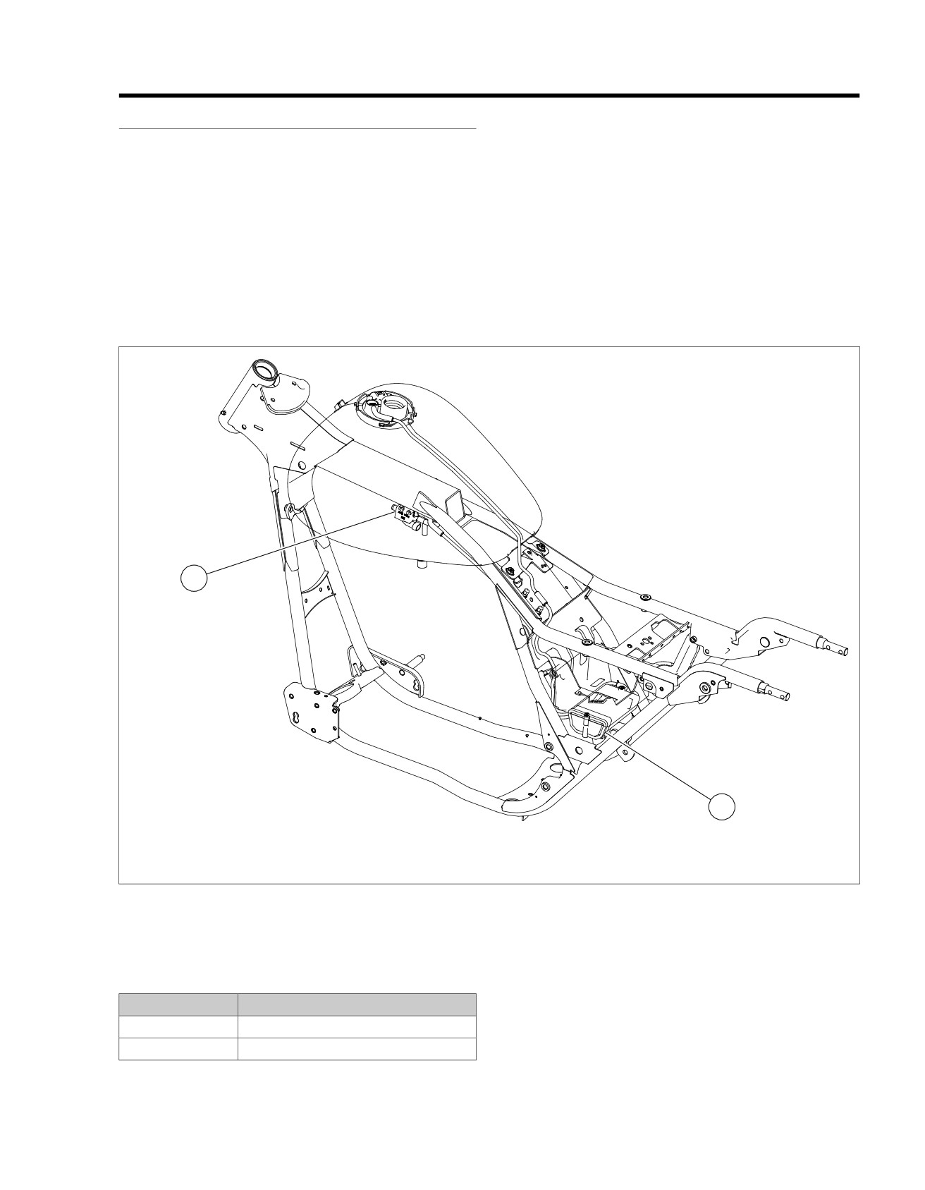
1
2
1. Purge solenoid
2. Charcoal canister
Figure 4-50. Purge Solenoid Mounting Location
Table 4-40. Code Description
DTC
DESCRIPTION
P0444
Purge solenoid open/low
P0445
Purge solenoid high
2008 Touring Diagnostics: Engine Management 4-111
HOME
DIAGNOSTICS
ed02060
PART NUMBER
TOOL NAME
HD-34730-2C
FUEL INJECTOR TEST LAMP
HD-34730-2C
FUEL INJECTOR TEST LAMP
HD-41404-B
HARNESS CONNECTOR TEST KIT
HD-48637
BREAKOUT BOX
Each reference number below correlates to a circled number
on the flow chart(s).
Diagnostic Notes
1. See Service Manual for all service information.
2. Use HARNESS CONNECTOR TEST KIT (Part No. HD-
41404-B), purple terminal probes and patch cord to and
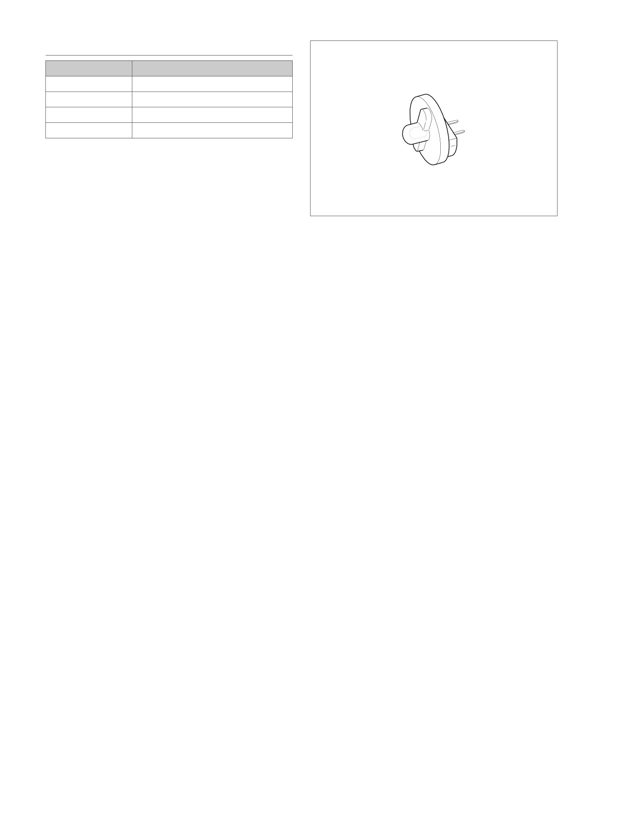
Figure 4-51. Fuel Injector Test Lamp (Part No. HD-34730-2C)
gray socket probes and patch cord to FUEL INJECTOR
TEST LAMP (Part No. HD-34730-2C). See Figure 4-51.
3. Use HARNESS CONNECTOR TEST KIT (Part No. HD-
Diagnostic Procedure
41404-B), purple terminal probe and patch cord.
NOTE
4. Connect a BREAKOUT BOX (Part No. HD-48637) to the
To access the purge solenoid and canister, the fuel tank must
ECM and mating connector. See 4.7 BREAKOUT BOX:
be removed from the vehicle.
EFI.
See Figure 4-52 and Figure 4-53 for purge solenoid circuitry
5. Use FUEL INJECTOR TEST LAMP (Part No. HD-34730-
diagrams.
2C) to test the purge solenoid circuit by plugging the test
1. See Service Manual and properly remove the fuel tank
lamp into connector [95B]. See Figure 4-51.
from the vehicle.
2. If the charcoal canister requires removal, refer to Service
Manual and remove/replace as required.
3. Check all of the formed plastic hoses and rubber hoses
for air leaks, cracks, breaks, chafing and/or physical
deterioration/wear. See Service Manual and replace any
hoses found defective.
4. Proceed with flow charts.
4-112 2008 Touring Diagnostics: Engine Management
HOME
em00142
[30A] [30B]
Ignition
2
2
GY
TSM/TSSM/HFSM
Electronic Control Module
[78A] [78B]
System
Relay
30(3)
87(5)
To
Purge solenoid
20
20
GY/Y
BE/GY
Y/GN
fuel pump
W/BK
GN/O
fuse
86(1)
85(2)
System relay enable
27
27
GN/O
MAXIFUSE
40 Amp
[5B]
ECM
BA
Fuse
15 Amp
BE/GY
(+)
(-)
Battery
[33B]
Ignition
Fuse
1
15 Amp
R
2
GY
R/BK
3
Ignition
Switch
[33A]
[1A]
[95B]
3
6
Main
AB
Harness
3
6
AB
[1B]
[95A]
12V battery
71
71
BE/GY
12V stop switch
72
72
W/BK
Ground
73
73
BK/GN
[22B]
Purge
Solenoid
3
4
Right-Hand
Rear
3
4
Controls
Clean
[22A]
Ground
Engine
Stop
Switch
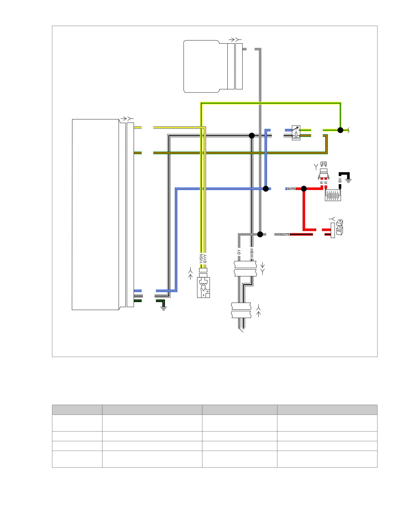
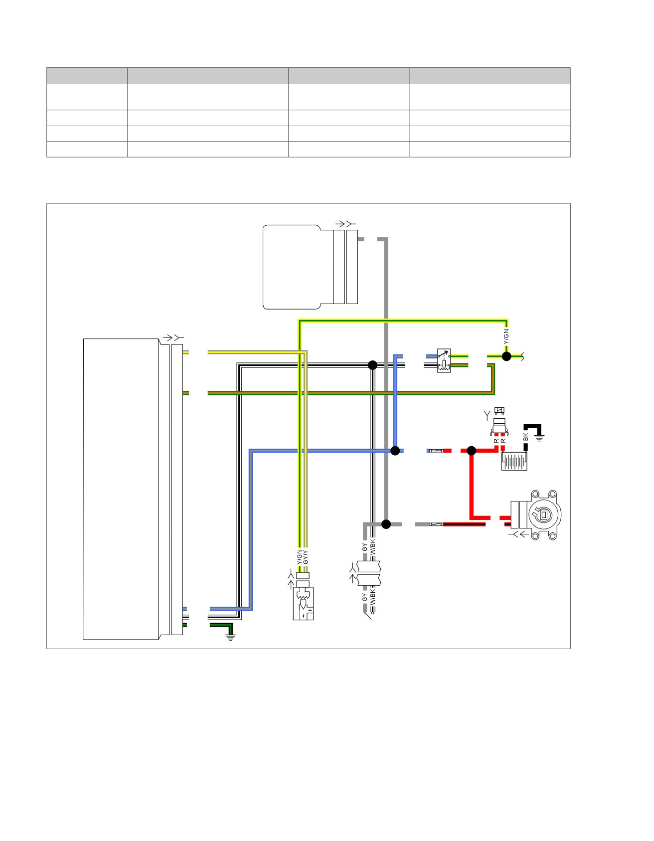
Figure 4-52. Purge Solenoid Circuit Diagram (FLHTP, FLHX, FLHT/C/CU, FLTR, FLTRU)
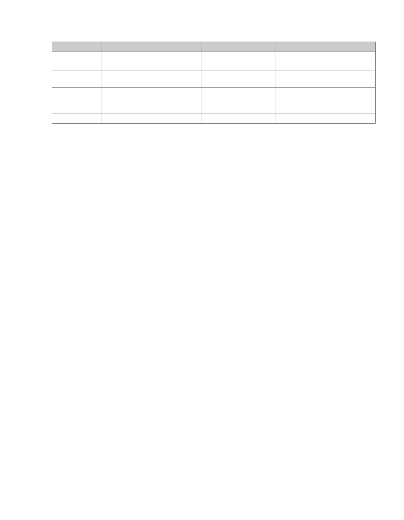
Table 4-41. Wire Harness Connectors
NO.
DESCRIPTION
TYPE
LOCATION
[1]
Main harness
16-place Molex
Inner fairing (right radio support
bracket)
[5]
MAXIFUSE
2-place Packard
Under left side cover
[22]
Right hand controls
6-place Molex (black)
Inside headlamp nacelle (FLHR/C/S)
[22]
Right hand controls
12-place Molex (Black)
Inner fairing right fairing support brace
(FLHT/C/U)
2008 Touring Diagnostics: Engine Management 4-113
HOME
Table 4-41. Wire Harness Connectors
NO.
DESCRIPTION
TYPE
LOCATION
[30]
TSM/TSSM/HFSM
12-place Deutsch
Cavity in crossmember at rear of bat-
tery box
[33]
Ignition switch
3-place Molex
Inner fairing (under radio)
[78]
Electronic Control Module (ECM)
73-place Delphi
Under seat
[95]
Purge solenoid
2-place Packard
Under fuel tank
em00143
[30A] [30B]
Ignition
2
2
GY
TSM/TSSM/HFSM
Electronic Control Module
[78A] [78B]
System
Relay
30(3)
87(5)
To
Purge solenoid
20
20
GY/Y
BE/GY
Y/GN
fuel pump
W/BK
GN/O
fuse
86(1)
85(2)
System relay enable
27
27
GN/O
MAXIFUSE
[5B]
40 Amp
ECM
BA
Fuse
15 Amp
(+)
(-)
BE/GY
R
Battery
Ignition
D
Fuse
I
C
15 Amp
R
B
B
GY
R/BK
A
A
[33B]
[33A]
Ignition
3
4
Switch
[22B]
Right Hand
[95B]
AB
[22A]
3
4
Controls
[95A]
AB
12V battery
71
71
BE/GY
12V stop switch
72
72
W/BK
Ground
73
73
BK/GN
Rear
Engine
Purge
Clean
Stop
Solenoid
Ground
Switch
Figure 4-53. Purge Solenoid Circuit Diagram (FLHR, FLHRC)
4-114 2008 Touring Diagnostics: Engine Management
HOME
Table 4-42. Wire Harness Connectors
NO.
DESCRIPTION
TYPE
LOCATION
[5]
MAXIFUSE
2-place Packard
Under left side cover
[22]
Right hand controls
6-place Molex (Black)
Inside headlamp nacelle
[30]
TSM/TSSM/HFSM
12-place Deutsch
Cavity in crossmember at rear of bat-
tery box
[33
Ignition switch
3-place Packard
Inner fairing - under radio (front of
ignition switch housing)
[78]
Electronic Control Module (ECM)
73-place Delphi
Under seat
[95]
Purge solenoid
2-place Packard
Under fuel tank
2008 Touring Diagnostics: Engine Management 4-115
HOME
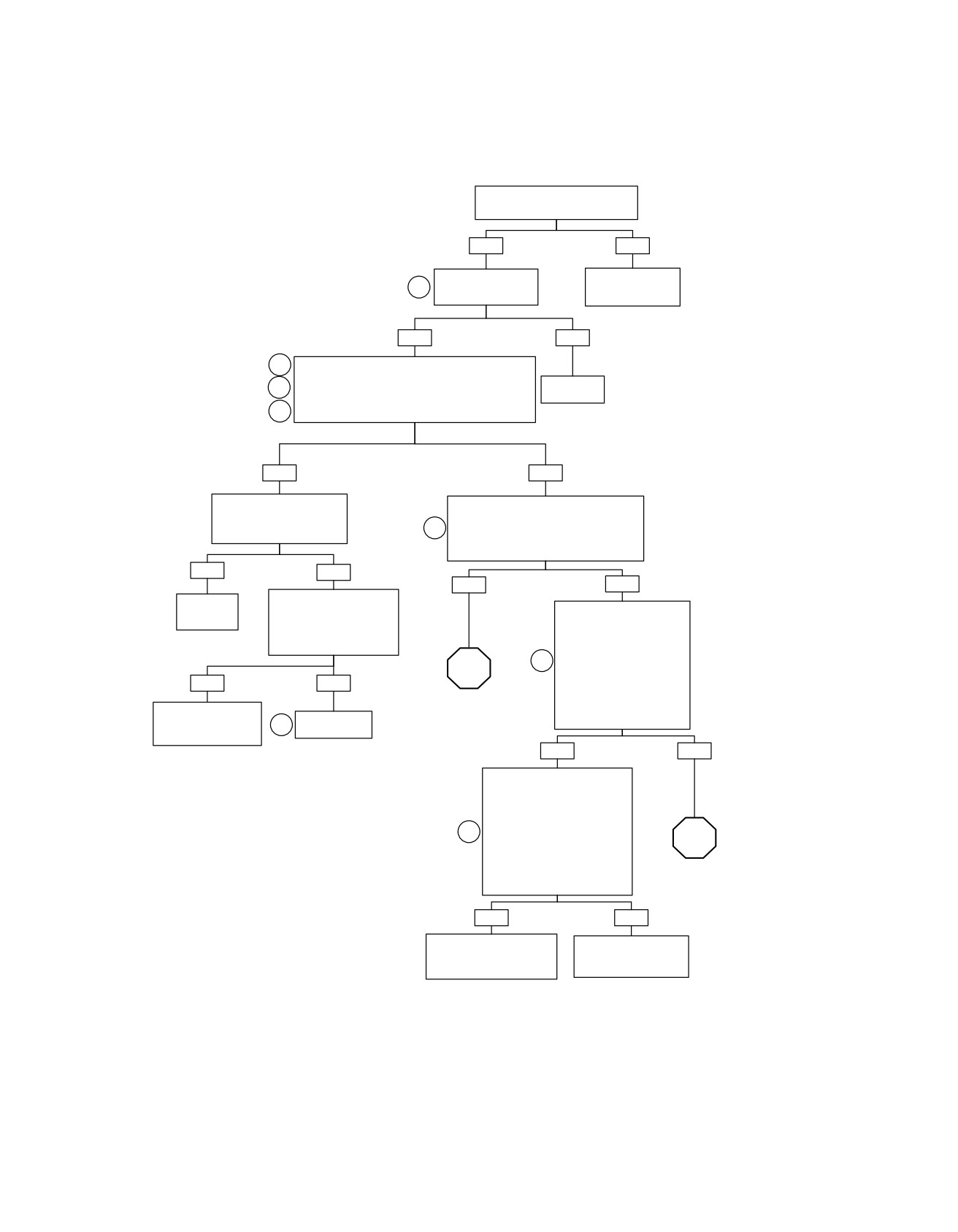
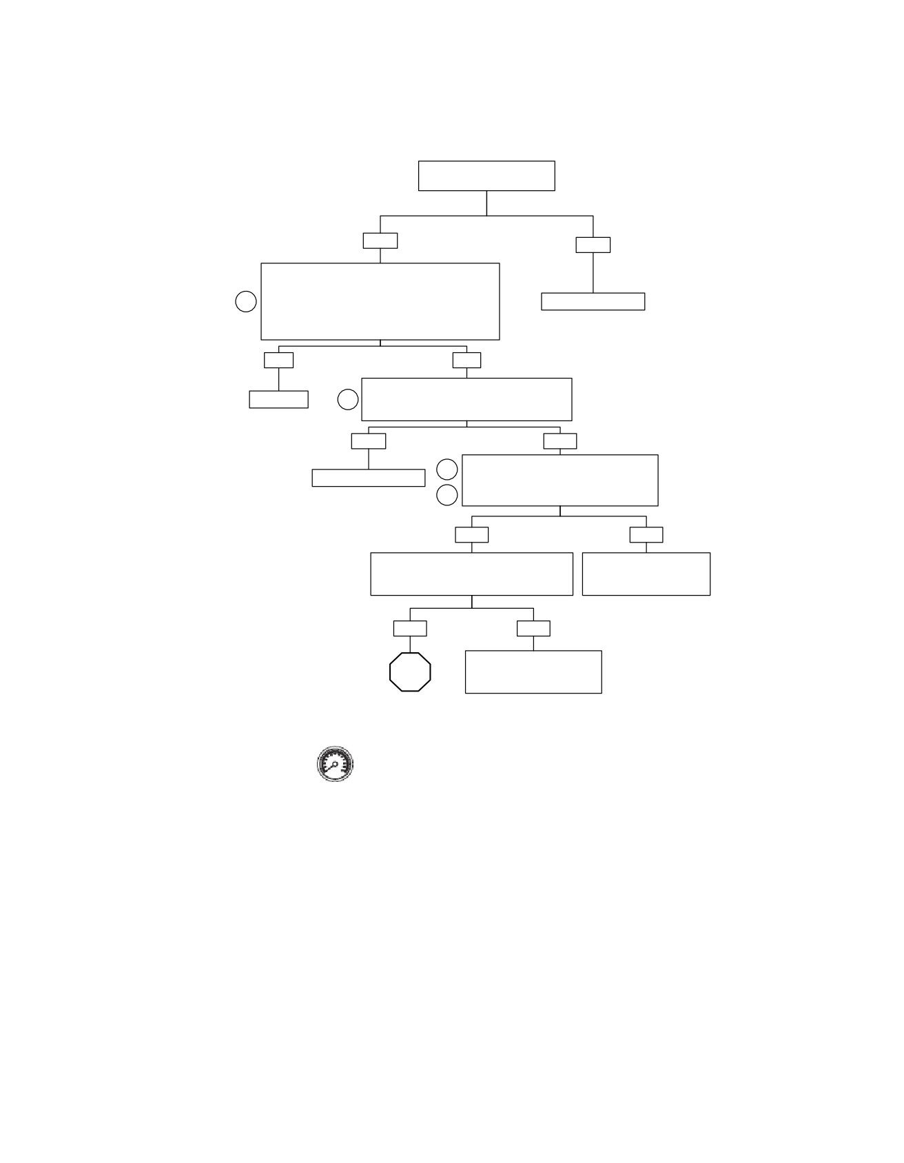
Purge Solenoid: DTC P0444, P0445 (Part 1 of 3)
Is vehicle a California, China,
Thailand or other foreign model?
YES
NO
Is connector securely
No Purge Solenoid
1
attached to the
Installed.
Purge Solenoid?
Reprogram ECM.
YES
NO
2
See Figure 4-51. Using Purge Solenoid Test
Lamp, turn Purge Solenoid on by grounding terminal
3
“20” using purple terminal probe and patch cord.
Reconnect.
Does test lamp illuminate for 2 seconds after Ignition
5
Switch is rotated to the IGNITION position?
YES
NO
Recheck connections.
Check terminal “A” (Y/GN) wire on purge
Perform 4.8 WIGGLE TEST
solenoid connector [95B] to ground.
to check for intermittents.
3
Voltage equivalent to battery voltage for 2
Intermittents present?
seconds after Ignition Switch is rotated to
the IGNITION position?
YES
NO
YES
NO
Using a DVOM, measure
Repair
resistance of Purge
Check for 12 volts at terminal
intermittent.
Solenoid across solenoid
“87” of system relay during
terminals.
first 2 seconds after Ignition
Resistance 22-29 ohms?
Switch is rotated to the
3
IGNITION position.
STOP
Correct voltage present?
YES
NO
NOTE:
Depending on relay used
Go to Purge
relay socket terminal could
Check for loose
Replace
Solenoid: DTC P0444,
be shown as “5” or “4C”.
or corroded terminals
1
Purge solenoid.
P0445 (Part 2 of 3).
in harness.
YES
NO
System relay OK. Measure
resistance between terminal
“87” of system relay and
terminal “A” (Y/GN) wire at
Purge Solenoid connector [95B].
3
Resistance less than 0.5 ohm?
STOP
NOTE:
Depending on relay used relay
Go to Purge Solenoid:
socket terminal could be shown
DTC P0444, P0445
as “5” or “4C”.
(Part 3 of 3).
YES
NO
Perform 4.8 WIGGLE TEST
Find and repair bad
to check for intermittents.
connection or open on
Repair as necessary.
wire (Y/GN).
fc01552_en
4-116 2008 Touring Diagnostics: Engine Management
HOME
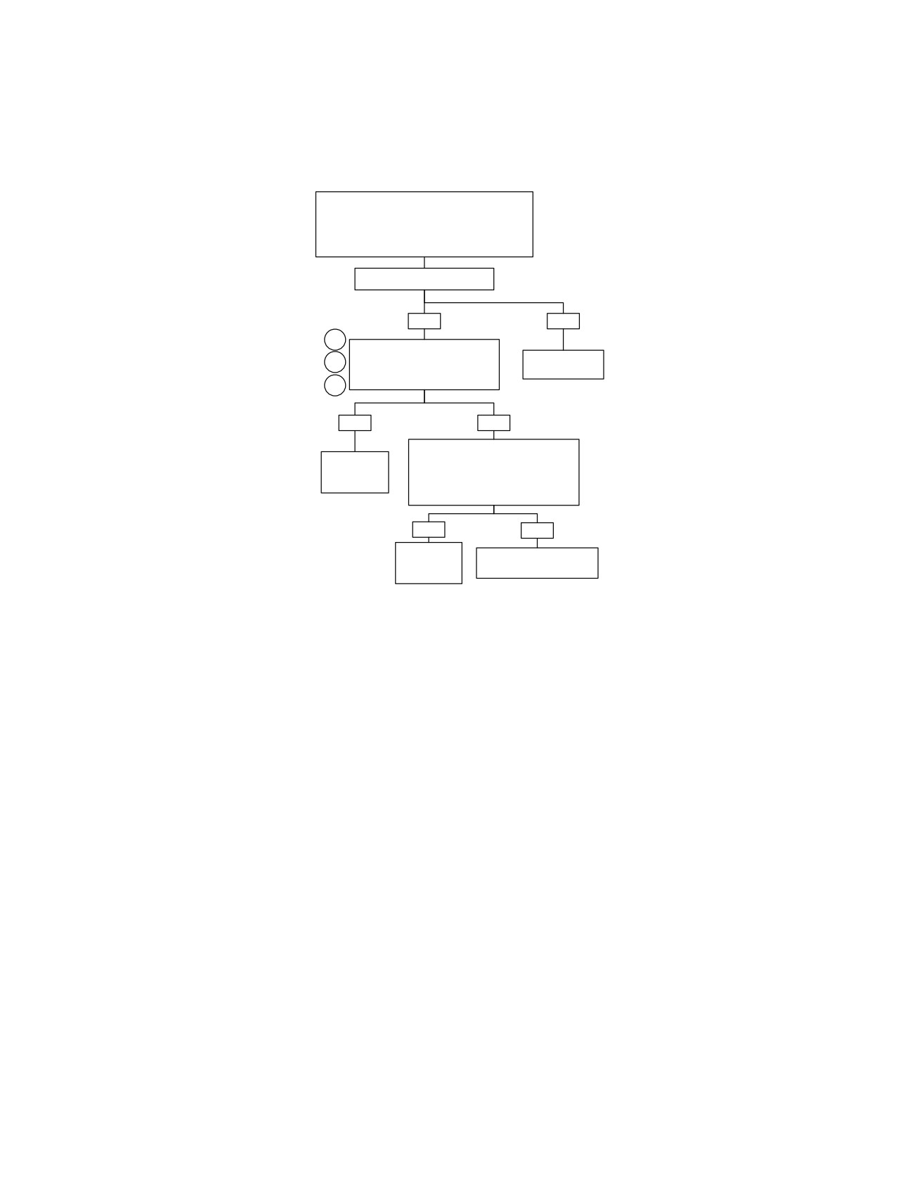
Purge Solenoid: DTC P0444, P0445 (Part 2 of 3)
Continued from Purge Solenoid: DTC P0444,
P0445 (Part 1 of 3).
Using a DVOM, measure resistance between
Breakout Box terminal “20” (GY/Y) wire and
terminal “B” of purge solenoid connector [95B].
Resistance less than 0.5 ohm?
YES
NO
2
Disconnect test light.
Check for continuity to ground on
Repair open or
3
Breakout Box terminal “20”.
poor connection.
4
Is continuity present?
YES
NO
Check for voltage within 2 seconds of
Repair short
The Ignition Switch position in the
to ground on
IGNITION position, at Breakout Box
wire (GY/Y).
terminal “20”.
Is battery voltage present?
YES
NO
Repair short
Replace ECM. Reprogram
to voltage on
and learn password.
wire (GY/Y).
fc01553_en
2008 Touring Diagnostics: Engine Management 4-117
HOME
Purge Solenoid: DTC P0444, P0445 (Part 3 of 3)
Continued from Purge Solenoid: DTC P0444, P0445
(Part 1 of 3).
Using DVOM, check for 12 volts at terminal “30” of the
System Relay.
Is correct voltage present?
NOTE:
Depending on relay used relay socket terminal could
be shown as “3” or “3D”.
YES
NO
Check for 12 volts at terminal
“86” of the System Relay.
Find and repair open
2
Correct voltage present?
between ECM
NOTE:
Fuse and System
3
Depending on relay used
Relay.
relay socket terminal could
be shown as “1” or “4D”.
YES
NO
Measure resistance between
terminal “86” of the System
Relay and ECM terminal “72”
2
on Breakout Box.
See 4.11 NO ECM
Resistance less than 0.5 ohm?
POWER.
3
NOTE:
Depending on relay used relay
socket terminal could be
shown as “1” or “4D”.
YES
NO
Measure resistance between
terminal “85” of the system relay
and ECM terminal “27” on
2
Breakout Box.
Find and repair
Resistance less than 0.5 ohm?
open on wire (W/BK).
3
NOTE:
Depending on relay used relay
socket terminal could be shown
as “2” or “3C”.
YES
NO
Install known good relay.
Does Fuel Pump run for
Find and repair
first 2 seconds after the
open on wire (GN/O).
Ignition Switch is rotated to
the IGNITION position?
YES
NO
Replace
Reinstall original System Relay
1
System
and replace ECM. Reprogram
Relay.
and learn password.
fc01554_en
4-118 2008 Touring Diagnostics: Engine Management
HOME
DTC P0501,
P0502
4.25
GENERAL
DIAGNOSTICS
Vehicle Speed Sensor (VSS)
PART NUMBER
TOOL NAME
See Figure 4-54. The VSS is powered and monitored by the
HD-41404-B
HARNESS CONNECTOR TEST KIT
ECM. The ECM processes the vehicle speed signal and
HD-48637
BREAKOUT BOX
transmits this signal to the TSM/TSSM/HFSM and speedometer
through serial data.
Diagnostic Notes
NOTE
Each reference number below correlates to a circled number
When the vehicle speed is greater than 0, the closed loop idle
on the flow chart(s).
speed control is inhibited.
1. The speedometer has a built-in diagnostic mode. See
4.6 SPEEDOMETER SELF-DIAGNOSTICS.
Table 4-43. Code Description
2. Use HARNESS CONNECTOR TEST KIT (Part No. HD-
DTC
DESCRIPTION
41404-B), gray pin probe and patch cord.
P0501
VSS low
3. Connect BREAKOUT BOX (Part No. HD-48637) between
wire harness and ECM. See 4.7 BREAKOUT BOX: EFI.
P0502
VSS high/open
ed03010
Figure 4-54. VSS Location (Under Starter)
2008 Touring Diagnostics: Engine Management 4-119
HOME
em00103
Electronic
[78A]
[78B]
Control Module
Vehicle speed input
40
40
W/GN
5V sensor power-1
50
50
BN/O
[65B] [65A]
BN/O
Vehicle
W/GN
Speed
Vehicle speed ground
64
64
BK/Y
BK/Y
Sensor
Figure 4-55. VSS Circuit Diagram
Table 4-44. Wire Harness Connectors
NO.
DESCRIPTION
TYPE
LOCATION
[65]
Vehicle Speed Sensor (VSS)
3-place Delphi
Top of transmission case (under
starter)
[78]
Electronic Control Module (ECM)
73-place Delphi
Under seat
4-120 2008 Touring Diagnostics: Engine Management
HOME
Vehicle Speed Sensor: DTC P0501, P0502 (Part 1 of 2)
Inspect connector [65].
Is connector mated properly?
YES
NO
Remove and inspect Vehicle Speed Sensor. Inspect for
debris and clean if necessary. Place Speedometer
into diagnostic mode and clear fault codes. Connect
1
Mate connector [65].
all circuits and ride motorcycle for approximately 1.0
mile (1.6 km). Check for Speedometer function.
Speedometer functioning properly?
YES
NO
Check for continuity between terminal
System OK.
2
“1” of connector [65B] (BN/O) wire and ground.
Continuity present?
YES
NO
Check for continuity between terminal “1”
2
Repair short to ground.
of connector [65B] (BN/O) wire and terminal
“50” of Breakout Box.
3
Continuity present?
YES
NO
Check for continuity between terminal “3" of
Locate and repair open on
connector [65B] (BK/Y) wire and terminal “64”.
(BN/O) wire between
Continuity present?
connectors [78B] and [65B].
YES
NO
Repair open on (BK/Y) wire
STOP
between connector [65B] and
terminal “64”.
Go to Vehicle Speed Sensor:
DTC P0501, P0502
(Part 2 of 2).
Clear codes using speedometer self diagnostics. See 4.6 SPEEDOMETER
SELF DIAGNOSTICS. Confirm proper operation with no check engine lamp.
fc01045_en
2008 Touring Diagnostics: Engine Management 4-121
HOME
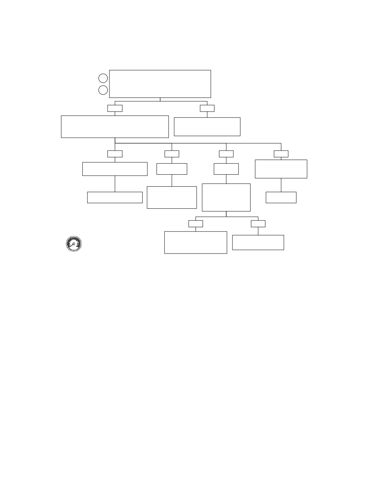
Vehicle Speed Sensor: DTC P0501, P0502 (Part 2 of 2)
Continued from Vehicle Speed Sensor: DTC P0501,
2
P0502 (Part 1 of 2).
Check for continuity between terminal “2” of connector
3
[65B] and terminal “40” of Breakout Box.
Continuity present?
YES
NO
Check for voltage at terminal “40” on Breakout Box. Meter
Locate and repair open on
should read 4.0-6.0 volts when gear tooth absent and 0.0-
(W/GN) wire between connectors
1.0 volt when gear tooth is present.
[78B] and [65B].
Does it?
YES
NO
NO
NO
No voltage fluctuation from
Voltage fluctuates from high
Battery voltage
No voltage
high (4.0-6.0 volts) to low
(4.0-6.0 volts) to low (0.0-1.0 volt).
present.
present.
(0.0-1.0 volt).
Measure continuity to
Locate and repair short to
Ground from terminal
Replace ECM. Reprogram
voltage on (W/GN) wire
“40” on Breakout Box.
Replace VSS.
and learn password.
between connectors [78B]
Is resistance less
and [65B].
than 100 ohms?
YES
NO
Clear codes using speedometer self
Locate and repair short to
diagnostics. See 4.6 SPEEDOMETER
Ground on (W/GN) wire
Replace ECM. Reprogram
SELF DIAGNOSTICS. Confirm proper
between connectors [78B]
and learn password.
operation with no check engine lamp.
and [65B].
fc01046_en
4-122 2008 Touring Diagnostics: Engine Management
HOME
DTC P0562,
P0563
4.26
GENERAL
NOTES
Battery Voltage
•
Warm idle speed will be automatically increased if battery
voltage is low at idle.
Battery voltage is monitored by the ECM (terminal "72"). If the
battery voltage fails to meet normal operating parameters, a
•
TSM/TSSM/HFSM problems may also set DTC P0562 or
code is set.
P0563.
•
When battery voltage at low RPM (<1300 RPM) is less
Table 4-45. Code Description
than 12.5 volts and battery voltage at high RPM (>2000
RPM) minus battery voltage at low RPM is less than 0.25
DTC
DESCRIPTION
volts, then DTC P0562 is set after 100 counts (up to 15
P0562
Battery voltage low
seconds).
P0563
Battery voltage high
•
DTC P0563 is displayed when battery positive voltage is
greater than 15.0 volts for more than 4 seconds.
2008 Touring Diagnostics: Engine Management 4-123
HOME
ed01260
1
2
3
4
19
5
18
6
7
17
8
16
9
15
14
13
12
11
10
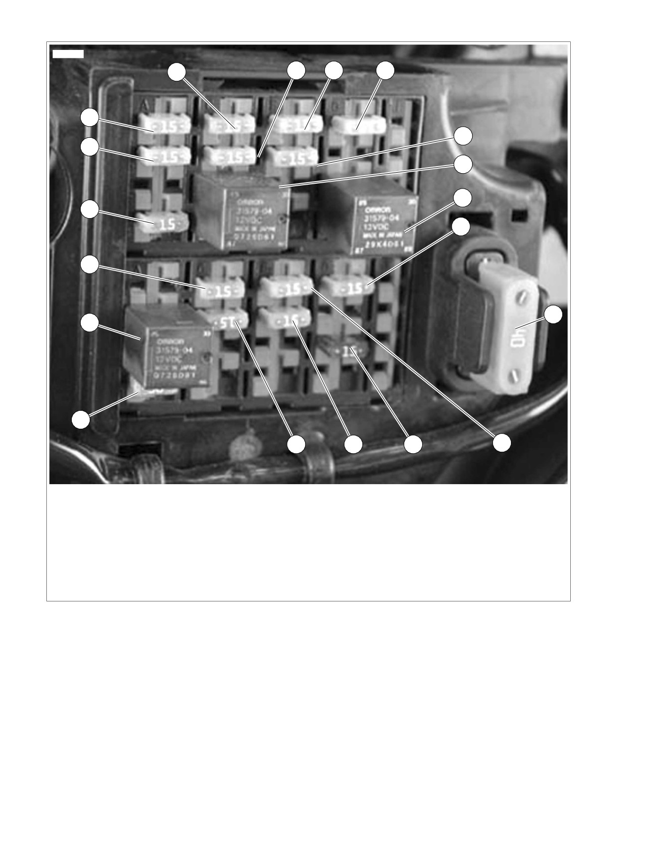
1. Accessory
11. Spare
2. Battery
12. Lights
3. P&A
13. Headlamp
4. Radio power/Siren (if equipped)
14. ABS (if equipped)
5. ECM power
15. Brake relay
6. System relay
16. Instruments
7. Start relay
17. Fuel pump
8. Engine control
18. Radio memory (if equipped)
9. MAXIFUSE
19. Brake/Cruise
10. Ignition
Figure 4-56. Fuse and Relay Locations
4-124 2008 Touring Diagnostics: Engine Management
HOME
2. Connect BREAKOUT BOX (Part No. HD-48637) between
DIAGNOSTICS
wire harness and ECM. See 4.7 BREAKOUT BOX: EFI.
PART NUMBER
TOOL NAME
3. Use DVOM with RPM Pick-up to check RPM on vehicles
HD-48637
BREAKOUT BOX
without tachometers.
Diagnostic Tips
4. This checks for voltage drops in the ECM circuit.
a. Place (+) probe to battery positive terminal.
•
Low voltage generally indicates a loose wire, corroded
connections, battery and/or a charging system problem.
b. Place (-) probe to (W/BK) terminal on BREAKOUT
BOX (Part No. HD-48637).
•
A high voltage condition may be caused by a faulty voltage
regulator.
5. Problem is most likely the ground connection at the frame.
Diagnostic Notes
6. Connect BREAKOUT BOX (Part No. HD-48637) to con-
Each referenced number below correlates with a circled number
nector [22]. FLHR/C models will also need HD-42962
on the flow chart(s).
adapters.
1. Was battery allowed to discharge? Was battery drawn
down by a starting problem?
a. Yes. Charge battery.
b. No. See 1.7 CHARGING SYSTEM, Troubleshooting.
To fuel
em00096
pump
1 2 3 4
[13A]
[126B] [126A]
15 Amp
86
(1)
Lighting
30(3)
87(5)
Electronic Control
Y/GN
BK
85
(2)
Relay
Module
[78A] [78B]
86(1)
R
30
(3)
85(2)
Fuel Pump
87A (4)
Fuse
87
(5)
To
System
fuel gauge
Relay
Stator
[77B]
[77A]
[47A]
[47B]
System relay enable
27
27
GN/O
BK
BK
2
BK
40 Amp
BK
1
BK
MAXIFUSE
Voltage
[5B]
B A
Regulator
Red
Band
15 Amp
(+)
(-)
BE/GY
ECM Fuse
1
Ignition
Battery
To
R
2
Switch
ignition
R/BK
3
[33A]
fuse
Starter
[33B]
12V battery
71
71
BE/GY
12V stop switch
72
72
W/BK
Ground
73
73
BK/GN
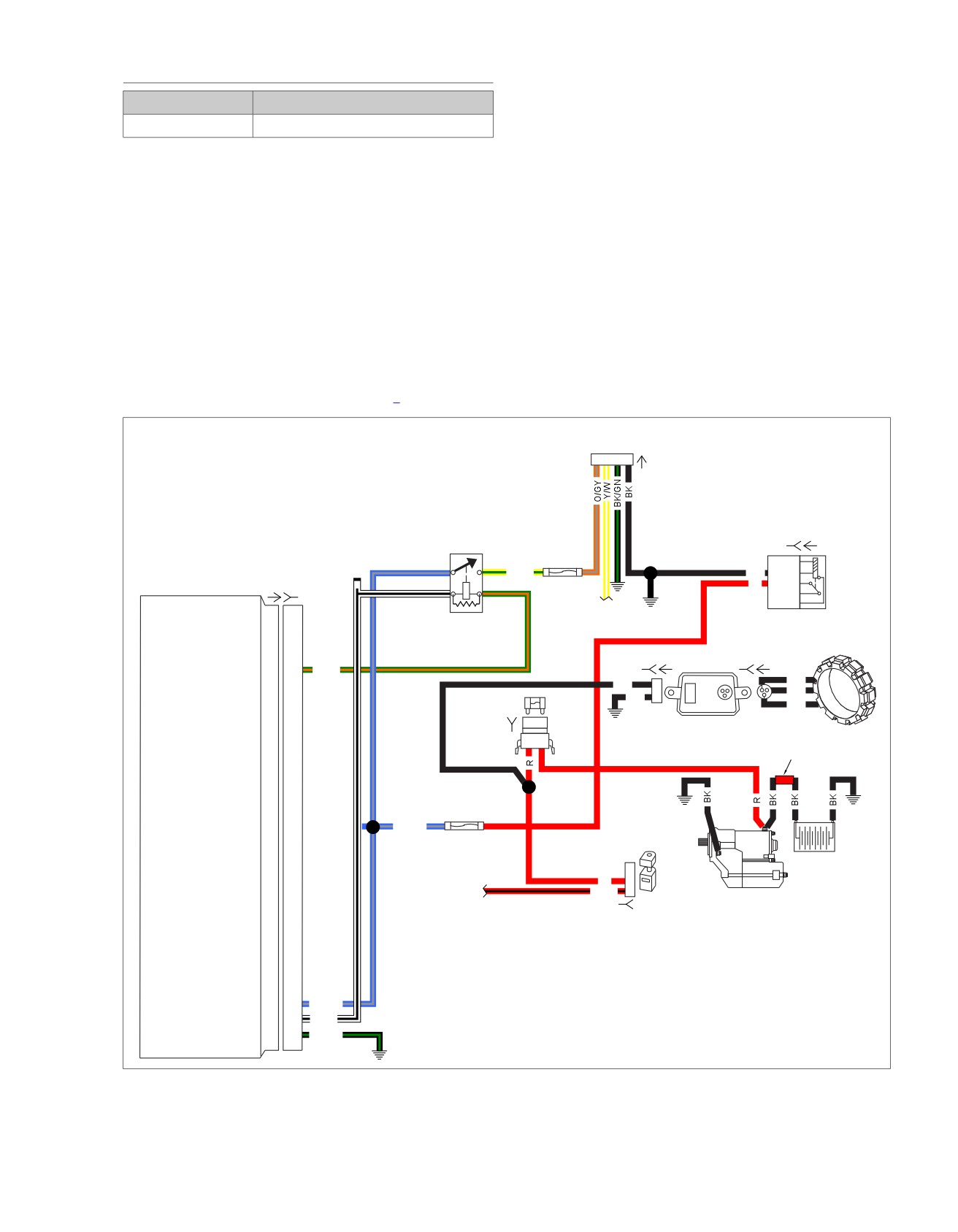
Figure 4-57. Battery Voltage Circuit Diagram (FLHX, FLHT/C/U, FLTR)
2008 Touring Diagnostics: Engine Management 4-125