Harley Davidson 2008 Touring Models. Electrical Diagnostics Manual - page 13
HOME
MISFIRE AT IDLE OR UNDER LOAD
4.16
GENERAL
ed02012
Misfire at Idle or Under Load
•
Battery condition and connections may also cause misfires.
See Battery in the Service Manual for more information.
•
Fuel system problems may also cause misfires. Consult
4.15 FUEL PRESSURE TEST and then see symptom
tables under 4.5 INITIAL DIAGNOSTIC CHECK: EFI.
•
Mechanical problems with the engine may cause misfires.
See Section 3 of the Service Manual for more information.
•
Vehicle modifications including intake and exhaust may
cause misfires.
DIAGNOSTICS
PART NUMBER
TOOL NAME
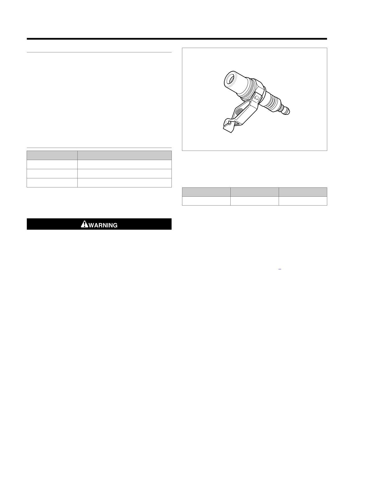
Figure 4-34. Spark Tester
HD-26792
SPARK TESTER
HD-41404-B
HARNESS CONNECTOR TEST KIT
HD-48637
BREAKOUT BOX
Table 4-21. Spark Plug Cables
LOCATION
LENGTH
RESISTANCE
Diagnostic Notes
Front/Rear
20.2 in. (513 mm)
4975-11960
Each reference number below correlates to a circled number
on the flow chart(s).
3.
Perform spark plug cable resistance test.
a. Remove spark plug cable from Spark Plug and Igni-
tion Coil. For best results, use a needle nose pliers
for removal/installation on coil. Gently grasp cable as
Wipe up spilled fuel and dispose of rags in a suitable
close to terminals as possible.
manner. An open spark around gasoline could cause a
fire or explosion, resulting in death or serious injury.
b. Using an ohmmeter, touch probes to terminals on
(00518b)
each end of the spark plug cable.
1. Connect BREAKOUT BOX (Part No. HD-48637) between
c. Compare resistance values to Table 4-21. Replace
wire harness and ECM. See 4.7 BREAKOUT BOX: EFI.
cables not meeting specifications. Reinstall and repeat
procedure on other spark plug cable.
NOTE
Engine will not spark with both spark plugs removed. When
4.
If carbon tracking is evident on outside of coil towers,
checking for spark, use SPARK TESTER (Part No. HD-26792)
replace ignition coil and inspect spark plug cables. Cables
with both plugs installed.
must be clean and tight. Excessive cable resistance or
2. See Figure 4-34. A SPARK TESTER (Part No. HD-26792)
faulty connections can cause coil damage.
must be used to verify adequate secondary voltage
5.
This test can also be performed by substituting a known
(25,000 volts) at the spark plug.
good coil for one causing the no spark condition. The coil
a. Turn Ignition Switch OFF.
does not require full installation to be functional. Verify
faulty coil by performing resistance test. See Ignition Coil
b. Remove spark plug cable from spark plug. Visually
in the Service Manual.
check plug condition.
6.
Use HARNESS CONNECTOR TEST KIT (Part No. HD-
c. Attach cable to SPARK TESTER. Clip tester to cyl-
41404-B) , red pin probe and patch cord to relay and gray
inder head bolt.
pin probe and patch cord to the coil connector [83B].
d. While cranking engine, watch for spark to jump tester
gap on leads.
e. Reinstall and repeat procedure on other spark plug
cable.
4-66 2008 Touring Diagnostics: Engine Management
HOME
em00095
Data Link
Fuel
ABCD
[141A]
1 2
3 4
Pump
[91A]
ABCD
[141B]
(GY)
Fuel Pump
Assembly in Tank
[83B] [83A]
Fuel Tank
Ignition Coil
Harness
Y/GN
A
A
Power
1234
[13B]
GY/BE
B
B
Ion sense
1234
[13A]
Y/BE
C
C
Coil rear
BE/O
D
D
Coil front
Electronic
Control
Module
[78A] [78B]
Fuel Pump
30(3)
87(5)
Fuse
BE/GY
Y/GN
MAXIFUSE
86(1)
85(2)
40 Amp
W/BK
GN/O
15 Amp
Exhaust actuator
21
21
V/O
To fuel
Rear injector
23
23
GN/GY
System
[5B]
gauge
BA
Relay
System relay enable
27
27
GN/O
(+)
(-)
Front injector
28
28
W/Y
ECM
Fuse
BE/GY
R
Ion sense
33
33
GY/BE
Battery
15 Amp
[84B] [84A]
Y/GN
A
A
Front
Exhaust feedback
38
38
V/BE
Ignition
[33B]
W/Y
B
B
Injector
Fuse
[85B] [85A]
R/GY
1
15 Amp
R
2
R/BK
R/BK
3
Y/GN
A
A
Rear
Ignition
GN/GY
B
B
Injector
Switch
[33A]
12V power
52
52
Y/GN
R/BK
Rear coil
53
53
Y/BE
Engine
Front coil
54
54
BE/O
Control
Fuse
15 Amp
Serial data
69
69
LGN/V
3
6
[1A]
Main
12V battery
71
71
BE/GY
Harness
12V stop switch
72
72
W/BK
[1B]
3
6
Ground
73
73
BK/GN
Rear
Clean
Ground
Right
[22B]
3 4
[179B]
Hand
43
2
1
[22A]
3
4
Controls
Active
Exhaust
(HDI only)
Engine Stop
Switch
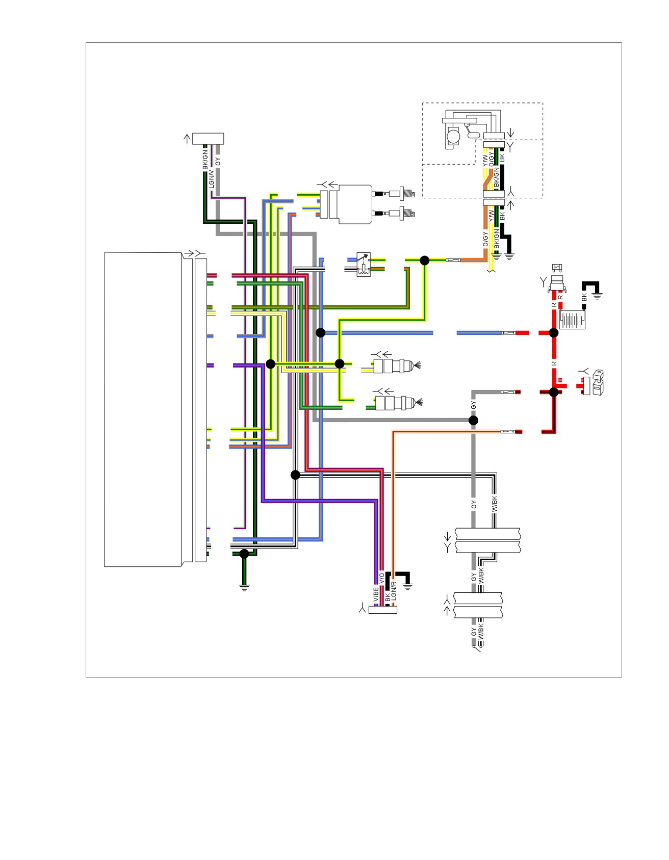
Figure 4-35. Ignition Coil Circuit Diagram
2008 Touring Diagnostics: Engine Management 4-67
HOME
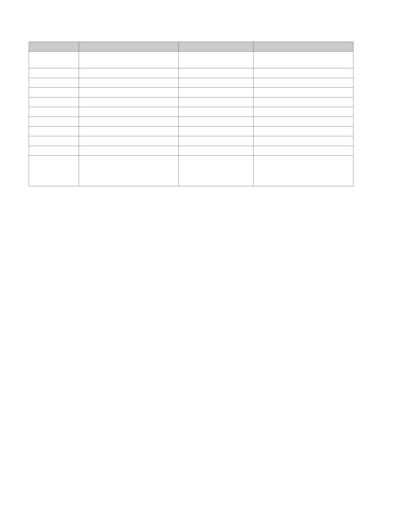
Table 4-22. Wire Harness Connectors
NO.
DESCRIPTION
TYPE
LOCATION
[1]
Main to interconnect harness
16-place Molex (black)
Inner fairing (right radio support
bracket)
[5]
MAXIFUSE
2-place Packard
Under left side cover
[13]
Fuel tank harness
4-place Multilock
Behind fuel tank (under seat)
[22]
Right handlebar switches
12-place Molex (black)
Inner fairing (fork stem nut lock plate)
[33]
Ignition switch
3-place Packard
Inner fairing (under radio)
[78]
Electronic Control Module (ECM)
73-place Delphi
Under seat
[83]
Ignition coil
4-place Delphi
Below fuel tank (left side)
[84]
Front injector
2-place Delphi
Below fuel tank (left side)
[85]
Rear injector
2-place Delphi
Below fuel tank (left side)
[91]
Data link connector
4-place Deutsch
Under left side cover
[179]
Active exhaust actuator
5-place Amp (Tyco)
Domestic (not used): Under right side
cover
HDI: Under right side cover (behind
electrical bracket)
4-68 2008 Touring Diagnostics: Engine Management
HOME
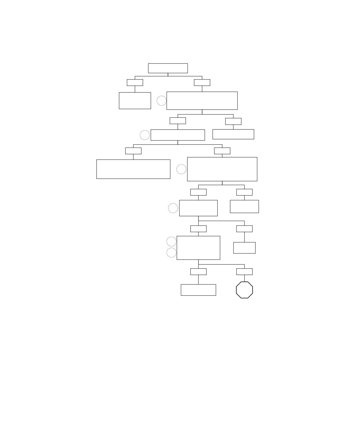
Misfire at Idle or Under Load (Part 1 of 3)
Is fuel contaminated?
YES
NO
Connect Breakout Box. Check for continuity
Drain and flush
between terminal “73” of ECM and Battery
Fuel Tank. Refill
1
negative terminal.
with fresh fuel.
Is resistance less than 1 ohm?
YES
NO
Use spark tester to check cables.
Locate and repair poor
2
Did spark jump tester lead gap?
ground connection.
YES
NO
Check resistance of each Spark Plug
Check for:
cable that did not fire the spark tester.
• Faulty, worn or cracked Spark Plug(s).
3
Also, check for faulty Spark Plug Cable
• Plug fouling due to engine mechanical fault.
connections and wires for carbon tracking.
• Faulty or poor connection at plug or coil.
Are Spark Plug Cables OK?
YES
NO
Replace faulty
Coils should be free
Spark Plug
4
of carbon tracking.
Cables.
Are they?
YES
NO
Switch coil with unit
2
known to be good.
Replace
Re-perform spark test.
Ignition Coil.
5
Did spark jump gap
during engine cranking?
YES
NO
Original ignition coil
STOP
is faulty. Replace.
Go to Misfire At Idle
or Under Load
(Part 2 of 3).
fc01026_en
2008 Touring Diagnostics: Engine Management 4-69
HOME
Misfire at Idle or Under Load (Part 2 of 3)
Continued from Misfire At Idle Or Under
Load (Part 1 of 3).
Measure resistance between system relay
terminal “87” and terminal “A” (Y/GN) wire
6
of connector [83B].
NOTE:
Depending on relay used relay socket terminal
could be shown as “5” or “4C”.
Wiggle harness.
Is resistance continuously less than 0.5 ohms?
YES
NO
Reassemble Ignition Coil and Fuel Tank.
Measure voltage drop between Battery (positive
lead) and terminal “87" (negative lead) on
Find source of
System Relay with engine running.
intermittent and repair.
NOTE:
Depending on relay used relay socket terminal
could be shown as “5” or “4C”.
Is voltage drop less than 1.0 volt?
YES
NO
Repeat voltage drop test after moving
negative lead to terminal “30”.
Problem is fuel related.
NOTE:
See symptoms under
Depending on relay used relay socket
Table 4-6. Engine
terminal could be shown as “3” or “3D”.
Performance Problems.
With engine running, is voltage drop less
than 1.0 volt?
YES
NO
Repeat voltage drop test after
moving negative lead to 15 amp
Replace
ECM Fuse (BE/GY) wire.
System Relay.
With engine running, is voltage drop
less than 1.0 volt?
YES
NO
Repeat voltage drop test after
moving negative lead to 15 amp
Repair.
ECM Fuse (R) wire.
(BE/GY) wire.
With engine running, is voltage
drop less than 1.0 volt?
YES
NO
Replace 15 amp
STOP
ECM Fuse.
Go to Misfire At Idle Or
Under Load
fc01027_en
(Part 3 of 3).
4-70 2008 Touring Diagnostics: Engine Management
HOME
Misfire at Idle or Under Load (Part 3 of 3)
Continued from Misfire At Idle Or Under
Load (Part 2 of 3).
Repeat voltage drop test after moving negative
lead to the 40 amp MAXIFUSE, terminal “B”.
With engine running, is voltage drop less than
1.0 volt?
YES
NO
Repeat voltage drop test after moving negative lead to
Check terminal
40 amp MAXIFUSE, terminal “A”.
or repair wire.
With engine running, is voltage drop less than 1.0 volt?
YES
NO
Repeat voltage drop test after
Check terminal
moving negative lead to Starter
or replace
Motor battery terminal.
MAXIFUSE.
With engine running, is voltage
drop less than 1.0 volt?
YES
NO
Repair wire between
Repair or replace
MAXIFUSE and
Battery Cable.
starter motor.
fc01028_en
2008 Touring Diagnostics: Engine Management 4-71
HOME
COMBUSTION ABSENT/INTERMITTENT
4.17
GENERAL
DIAGNOSTICS
Diagnostic Trouble Codes P1353, P1356,
PART NUMBER
TOOL NAME
P1357, P1358: No Combustion
HD-41404-B
HARNESS CONNECTOR TEST KIT
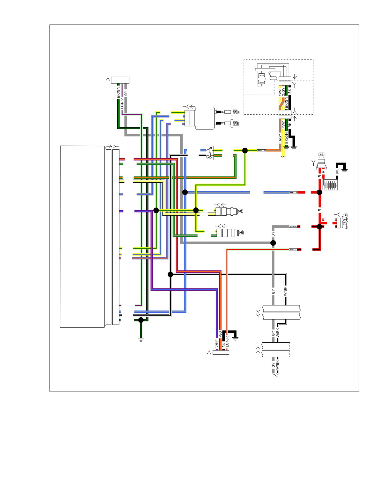
See Figure 4-36. A feedback voltage signal in the secondary
HD-48637
BREAKOUT BOX
ignition circuit detects the presence of combustion each time
a cylinder fires on ECM terminal "33". For diagnostic purposes,
Diagnostic Notes
this signal is only analyzed under load above 2000 RPM where
Each reference number below correlates to a circled number
it may be easily measured. Failure to detect combustion at
on the flow chart(s).
high speed and load means one of following conditions exist.
1. Connect BREAKOUT BOX (Part No. HD-48637) between
•
Cylinder is truly misfiring.
wire harness and ECM. See 4.7 BREAKOUT BOX: EFI.
•
There is a lack of continuity in the ignition coil secondary
2. Spark plugs must be correct Harley-Davidson resistor type
circuit.
specified for this model.
3. Use HARNESS CONNECTOR TEST KIT (Part No. HD-
Table 4-23. Code Description
41404-B), purple pin probes and patch cords.
DTC
DESCRIPTION
4. Perform spark plug cable resistance test.
P1353
Front cylinder no combustion
a. Remove spark plug cable from spark plug and ignition
P1356
Rear cylinder no combustion
coil. For best results, use a needle nose pliers for
removal/installation on coil. Gently grasp cable as
P1357
Intermittent secondary front
close to terminals as possible.
P1358
Intermittent secondary rear
b. Using an ohmmeter, touch probes to terminals on
each end plug wire.
ed02023
c. Compare resistance values to Table 4-24. Replace
cables not meeting specifications. Reinstall and repeat
procedure on other spark plug cable.
Table 4-24. Spark Plug Cables
LOCATION
LENGTH
RESISTANCE
Front/Rear
20.2 in. (513 mm)
4975-11960
Figure 4-36. Ignition Coil
4-72 2008 Touring Diagnostics: Engine Management
HOME
em00095
Data Link
Fuel
ABCD
[141A]
1 2
3 4
Pump
[91A]
ABCD
[141B]
(GY)
Fuel Pump
Assembly in Tank
[83B] [83A]
Fuel Tank
Ignition Coil
Harness
Y/GN
A
A
Power
1234
[13B]
GY/BE
B
B
Ion sense
1234
[13A]
Y/BE
C
C
Coil rear
BE/O
D
D
Coil front
Electronic
Control
Module
[78A] [78B]
Fuel Pump
30(3)
87(5)
Fuse
BE/GY
Y/GN
MAXIFUSE
86(1)
85(2)
40 Amp
W/BK
GN/O
15 Amp
Exhaust actuator
21
21
V/O
To fuel
Rear injector
23
23
GN/GY
System
[5B]
gauge
BA
Relay
System relay enable
27
27
GN/O
(+)
(-)
Front injector
28
28
W/Y
ECM
Fuse
BE/GY
R
Ion sense
33
33
GY/BE
Battery
15 Amp
[84B] [84A]
Y/GN
A
A
Front
Exhaust feedback
38
38
V/BE
Ignition
[33B]
W/Y
B
B
Injector
Fuse
[85B] [85A]
R/GY
1
15 Amp
R
2
R/BK
R/BK
3
Y/GN
A
A
Rear
Ignition
GN/GY
B
B
Injector
Switch
[33A]
12V power
52
52
Y/GN
R/BK
Rear coil
53
53
Y/BE
Engine
Front coil
54
54
BE/O
Control
Fuse
15 Amp
Serial data
69
69
LGN/V
3
6
[1A]
Main
12V battery
71
71
BE/GY
Harness
12V stop switch
72
72
W/BK
[1B]
3
6
Ground
73
73
BK/GN
Rear
Clean
Ground
Right
[22B]
3 4
[179B]
Hand
43
2
1
[22A]
3
4
Controls
Active
Exhaust
(HDI only)
Engine Stop
Switch
Figure 4-37. EFI Circuit
2008 Touring Diagnostics: Engine Management 4-73
HOME
Table 4-25. Wire Harness Connectors
NO.
DESCRIPTION
MODEL
TYPE
LOCATION
[1]
Main to interconnect har-
FLHT/C
16-place Molex (Black)
Inner fairing - right radio support bracket
ness
FL
TR
16-place Molex (Black)
Inner fairing - below radio (right side)
[5]
MAXIFUSE
ALL
2-place Packard
Under left side cover
[13]
Fuel tank harness
All
4-place Multilock
Behind fuel tank (under seat)
[22]
Right handlebar switches
FLHR/C/U
6-place Molex (Black
Inside headlamp nacelle
FLTR/C/X
12-place Molex (Black)
Inner fairing - right fairing support bracket
[33]
Ignition switch
FLHT/C/U
3-place Packard
Inner fairing - under radio (front of ignition
FLHTR
switch housing)
FLHR/C
3-place Packard
Under console
[78]
Electronic Control Module
All
73-place Delphi
Under seat
(ECM)
[83]
Ignition coil
All
4-place Delphi
Below fuel tank (left side)
[84]
Front injector
All
2-place Delphi
Below fuel tank (left side)
[85]
Rear injector
All
2-place Delphi
Below fuel tank (left side)
[91]
Data link connector
All
4-place Deutsch
Under left side cover
[141]
Fuel pump and fuel level
FLHX,
4-place Packard
Front right crankcase
sender
FLHT/C/U
FLHR/C/S,
4-place Packard
Top of canopy (under console)
FLTR
[179]
Active
All
5-place Amp (Tyco)
Domestic (not used): Under right side
cover
HDI: Under right side cover (behind elec-
trical bracket)
4-74 2008 Touring Diagnostics: Engine Management
HOME
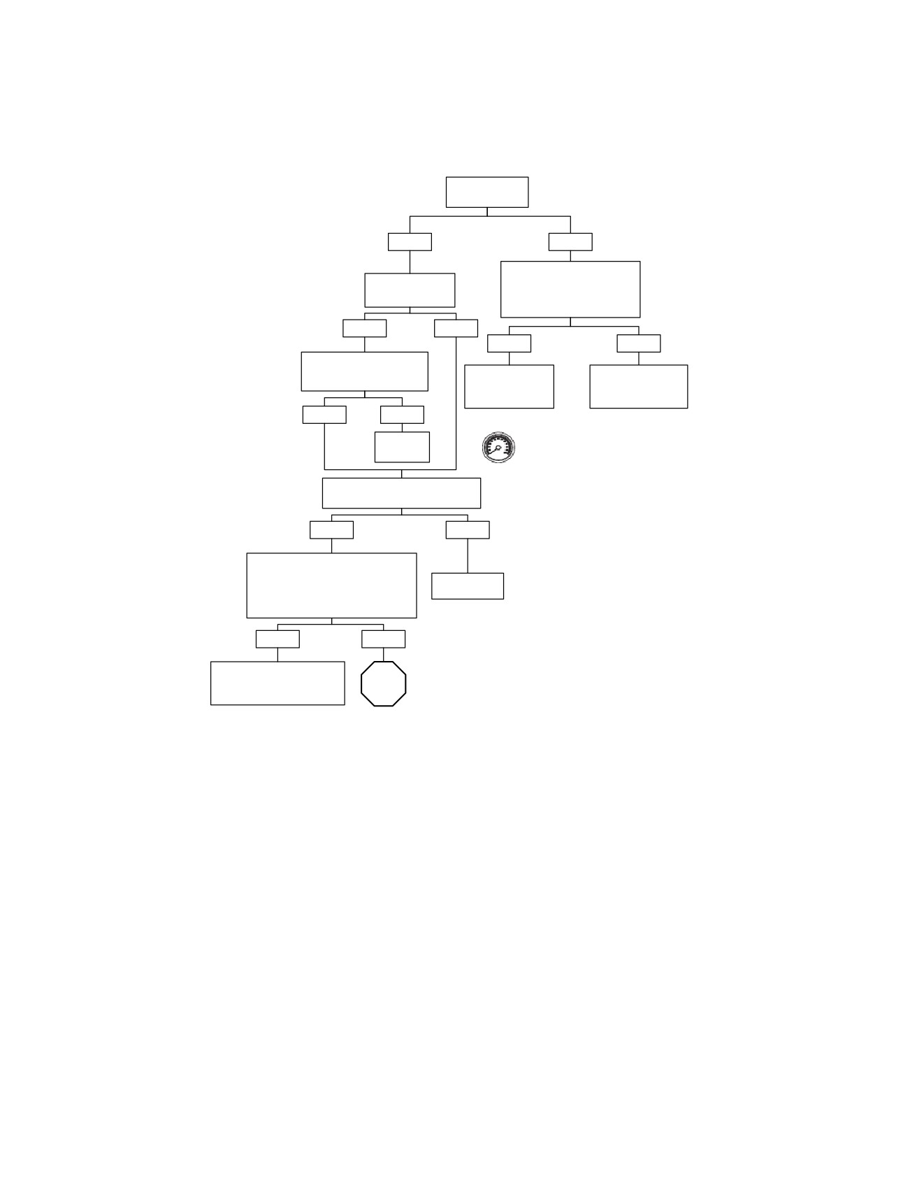
Combustion Absent (Part 1 of 2): DTC P1353, P1356, P1357, P1358
Is vehicle
running properly?
YES
NO
Check fuel pressure. See 4.15
Has vehicle run out
FUEL PRESSURE TEST.
of fuel recently?
Is fuel pressure 55-62 PSI
(380-425 kPa)?
YES
NO
YES
NO
Clear codes, refill with fresh
fuel and restart.
See 4.16
See 4.13
Does code return?
MISFIRE AT IDLE
FUEL SYSTEM
OR UNDER LOAD.
ELECTRICAL TEST.
YES
NO
Clear codes using speedometer self diagnostics.
System
See 4.6 SPEEDOMETER SELF DIAGNOSTICS.
OK.
Confirm proper operation with no check engine
lamp.
Check if spark plug terminal is fully
connected on Spark Plug.
YES
NO
Remove spark plug terminal from
Spark Plug. Inspect cable and spark
Seat terminal
plug terminals for carbon tracking or
on Spark Plug.
evidence of a loose terminal.
Loose terminal present?
YES
NO
Crimp spark plug terminal
slightly to improve connection
STOP
or replace Spark Plug Cable.
Go to Combustion Absent
fc01175_en
(Part 2 of 2): DTC P1353,
P1356, P1357, P1358.
2008 Touring Diagnostics: Engine Management 4-75
HOME
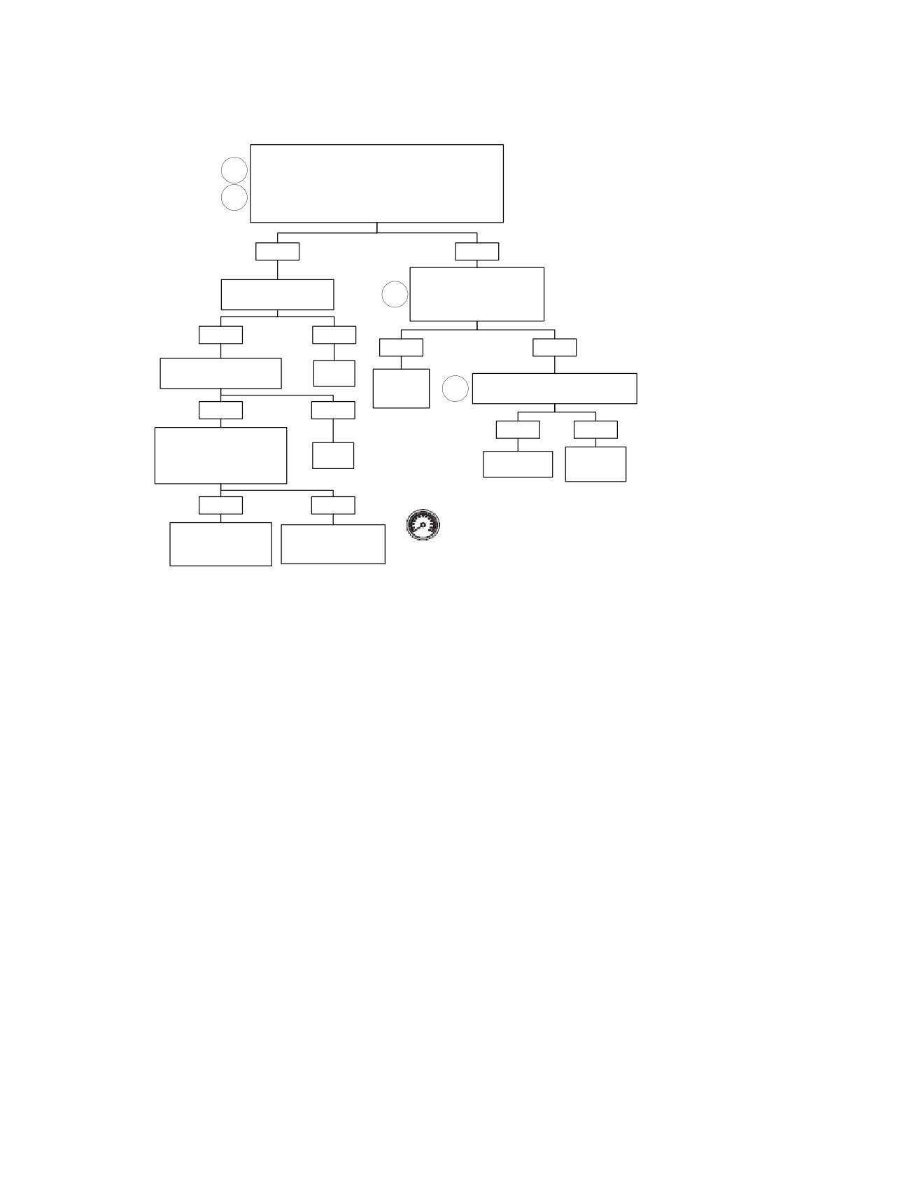
Combustion Absent (Part 2 of 2): DTC P1353, P1356, P1357, P1358
Continued from Combustion Absent (Part 1 of 2): DTC
P1353, P1356, P1357, P1358.
1
Using Breakout Box, measure resistance between Spark
2
Plug center electrode and Breakout Box terminal “33".
Is resistance less than 60,000 ohms?
YES
NO
Check continuity between
Replace Spark Plug.
Ignition Coil terminal “B” and
3
Is condition still present?
Breakout Box terminal “33”.
Is continuity present?
YES
NO
YES
NO
Replace Spark Plug Cable.
System
Is condition still present?
OK.
Replace
Check Spark Plug Cable resistance.
Ignition
4
Does resistance meet specifications?
Coil.
YES
NO
YES
NO
Measure resistance between
terminal “A” and “B” at coil.
System
Replace
Is resistance greater than
OK.
Replace Spark
Spark
100k ohms?
Plug.
Plug Cable.
YES
NO
Clear codes using speedometer self diagnostics. See
4.6 SPEEDOMETER SELF DIAGNOSTICS. Confirm
Replace ECM.
Replace coil and ECM.
proper operation with no check engine lamp.
Reprogram and learn
Reprogram and learn
password.
password.
fc01029_en
4-76 2008 Touring Diagnostics: Engine Management
HOME
DTC P0107,
P0108, P0112, P0113
4.18
GENERAL
TMAP: MAP Signal
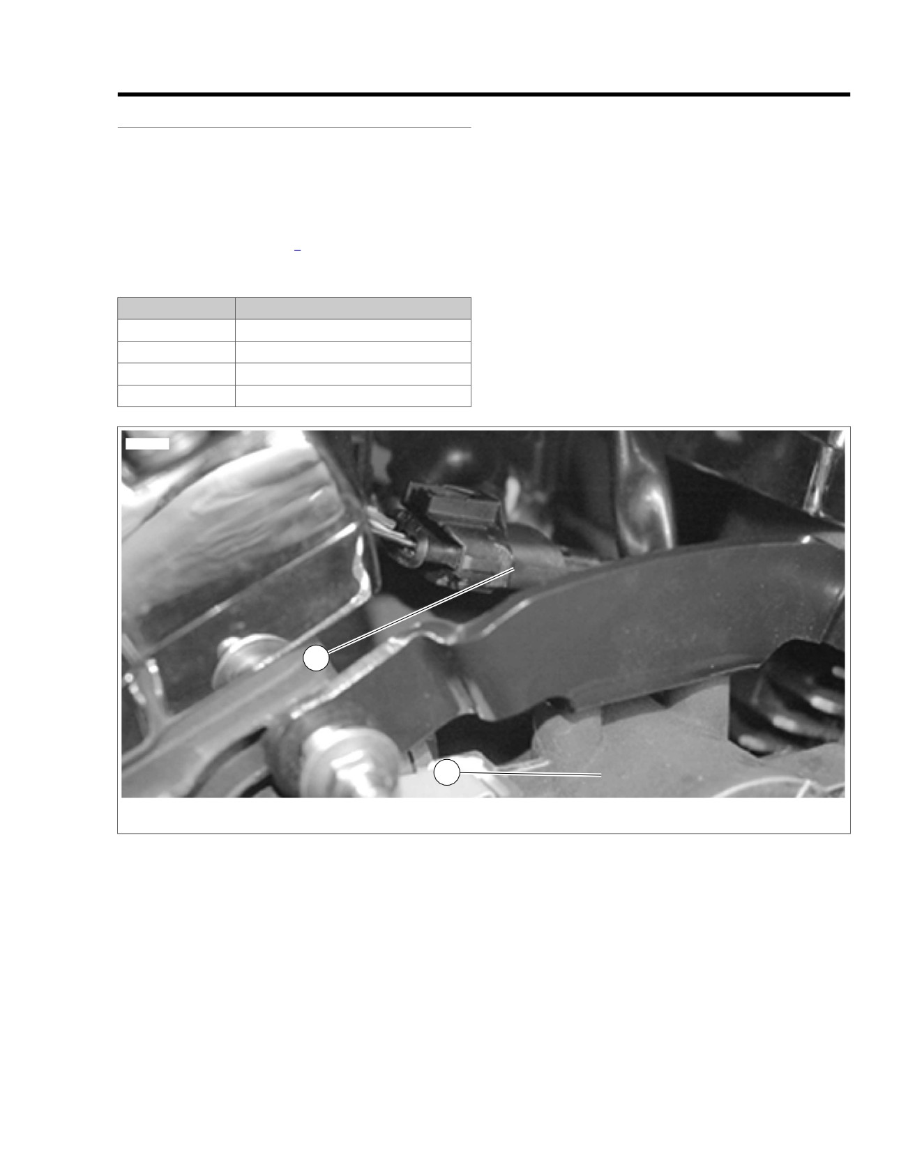
See Figure 4-38. The Temperature Manifold Absolute Pressure
The MAP signal varies in accordance with engine vacuum and
(TMAP) sensor provides the functions of both an Intake Air
atmospheric pressure. Changes in atmospheric pressure are
Temperature (IAT) sensor and a Manifold Absolute Pressure
influenced by weather and altitude.
(MAP) sensor in one unit.
TMAP: IAT Signal
The TMAP sensor is supplied 5 volts from ECM terminal "68"
The IAT portion of the TMAP sensor is a thermistor device,
and sends MAP and IAT signals back to ECM terminals "24"
meaning that at a specific temperature, it will have a specific
and "49" respectively. Refer to Table 4-26.
resistance across its terminals. As this resistance varies, so
does the voltage on terminal "49" of the ECM.
Table 4-26. Code Description
•
At high temperatures, the resistance of the IAT sensor is
DTC
DESCRIPTION
very low, which effectively lowers the signal voltage on
terminal "49".
P0107
MAP sensor open/low
P0108
MAP sensor high
•
At low temperatures, the resistance is very high, allowing
the voltage to rise close to 5 volts.
P0112
IAT sensor voltage low
The ECM monitors this voltage to compensate for various
P0113
IAT sensor open/high
operating conditions.
ed01263
1
2
1. TMAP
2. Induction Module
Figure 4-38. TMAP Sensor Location
2008 Touring Diagnostics: Engine Management 4-77

HOME
in order to evaluate the possibility of a shifted (out-of-cal-
DIAGNOSTICS
ibration) sensor which may result in driveability problems.
PART NUMBER
TOOL NAME
•
An intermittent may be caused by poor connection, rubbed
HD-23738
VACUUM PUMP
through wire insulation or a wire broken within the wire?s
insulation.
HD-41404-B
HARNESS CONNECTOR TEST KIT
HD-41404-B
HARNESS CONNECTOR TEST KIT
Diagnostic Notes: TMAP Sensor
HD-48637
BREAKOUT BOX
Each reference number below correlates to a circled number
on the flow chart(s).
HD-48637
BREAKOUT BOX
1. Connect BREAKOUT BOX (Part No. HD-48637) between
Diagnostic Tips: MAP Portion of TMAP
wire harness and ECM. See 4.7 BREAKOUT BOX: EFI.
Sensor
2. Use HARNESS CONNECTOR TEST KIT (Part No. HD-
•
P0107 or P0108 codes will set if the MAP Sensor signal
41404-B), purple pin probes and patch cords.
is out of range. Code P0108 can only be detected with the
3. Connect BREAKOUT BOX (Part No. HD-48637) to main
engine running.
wire harness only
(leave ECM disconnected). See
•
MAP sensor output check. Using the VACUUM
4.7 BREAKOUT BOX: EFI.
PUMP (Part No. HD-23738), apply a vacuum to the pres-
4. Use HARNESS CONNECTOR TEST KIT (Part No. HD-
sure port of the TMAP sensor. The MAP signal voltage
41404-B), purple pin socket probes and patch cords.
should lower as the vacuum is applied.
•
The TMAP and TP sensors are connected to the same
5. Replace TMAP sensor. See Service Manual.
reference line (+5V Vref). If the reference line goes to
ground or open, multiple codes will be set (DTC P0107,
Table 4-27. TMAP: IAT Sensor Table
P0108, P0122, P0123, P1501, P1502).
TEMP °C
RESISTANCE
VOLTAGE
TEMP °F
Diagnostic Tips: IAT Portion of TMAP
-20
29121
4.9
-4
Sensor
-10
16599
4.8
14
Check the following conditions:
0
9750
4.6
32
•
Poor connection: Inspect ECM and harness connector
10
5970
4.3
50
[78] for backed out terminals, improper mating, broken
20
3747
4.0
68
locks, improperly formed or damaged terminals, poor ter-
minal-to-wire connection and damaged harness.
25
3000
3.8
77
•
Perform 4.8 WIGGLE TEST to locate intermittents: If
30
2417
3.6
86
connections and harness check out OK, use a DVOM to
40
1598
3.1
104
check the Intake Air Temperature Sensor voltage reading
50
1080
2.6
122
while moving related connectors and wiring harnesses. If
the failure is induced, then the IAT sensor voltage reading
60
746
2.2
140
will change.
70
526
1.7
158
•
Shifted sensor: Refer to Table 4-27. This table may be
80
377
1.4
176
used to test the IAT sensor at various temperature levels
90
275
1.1
194
100
204
0.9
212
4-78 2008 Touring Diagnostics: Engine Management
HOME
em00098
[78A]
[78B]
Electronic Control Module
TMAP Sensor
MAP sensor input
24
24
V/W
[80A]
1
2 3
4
1
2 3
4
[80B]
Intake air temperature
49
49
LGN/Y
BK/GY
5V sensor ground-2
62
62
5V sensor power-2
68
68
R/W
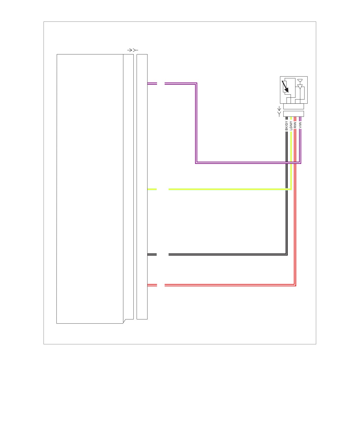
Figure 4-39. TMAP Sensor Circuit
2008 Touring Diagnostics: Engine Management 4-79
HOME
Table 4-28. Wire Harness Connectors
NO.
DESCRIPTION
TYPE
LOCATION
[78]
Electronic Control Module (ECM)
73-place Delphi
Under seat
[80]
T
emperature Manifold Absolute Pres-
4-place Packard
Top of induction module
sure (TMAP) sensor
4-80 2008 Touring Diagnostics: Engine Management
HOME
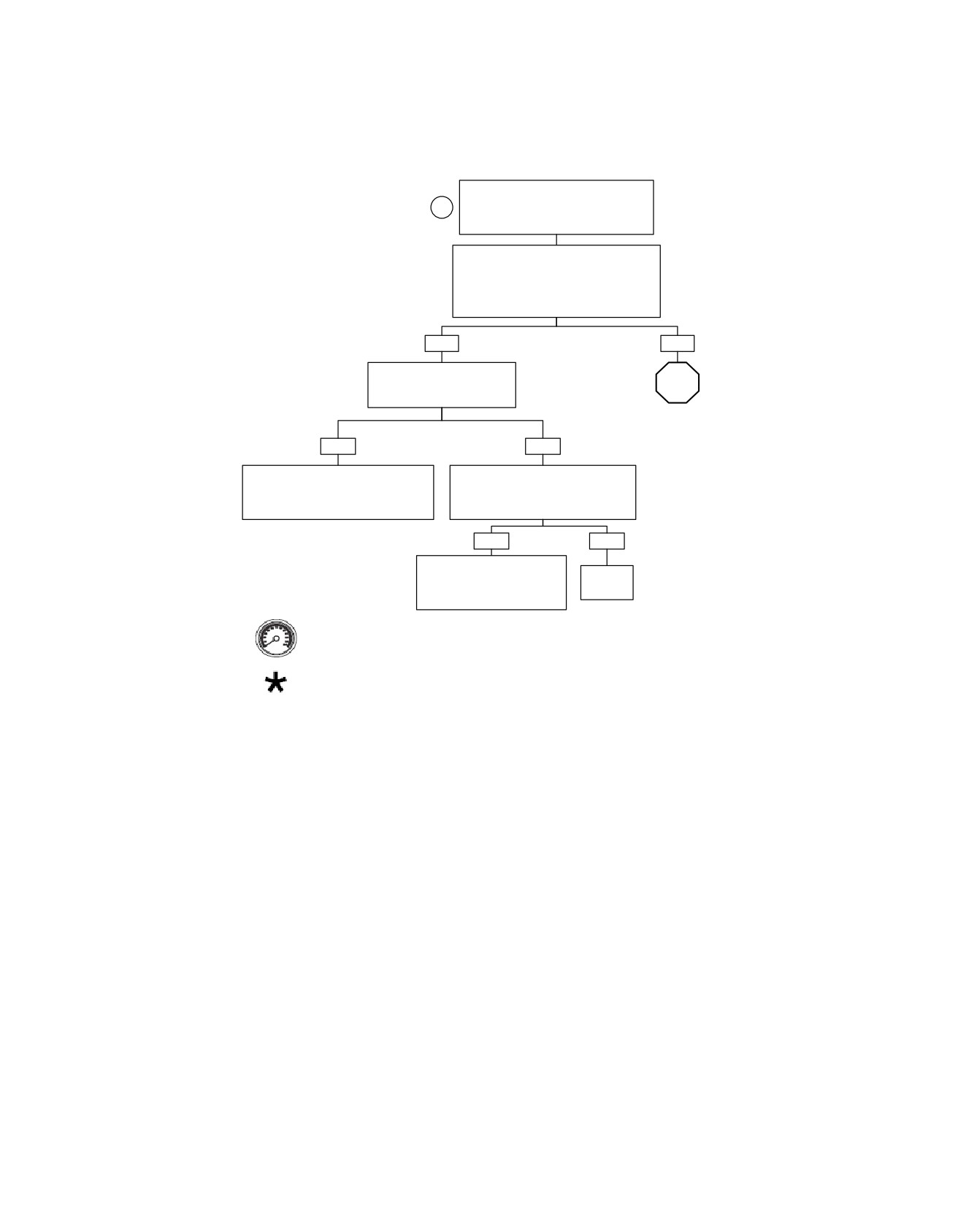
TMAP Diagnostics: DTC P0107, P0108, P0112, P0113 (Part 1 of 4)
Connect Breakout Box. With Ignition
Switch in IGNITION position,
1
measure voltage between terminal “24”
and terminal “62” on Breakout Box.
With Ignition Switch ON, engine OFF, voltage
must be between 3.5 and 5.0 volts. With
Ignition Switch ON, engine running, voltage
must be between 1.5-3.0 volts at hot idle.
Does voltage fit specifications?
YES
NO
Perform 4.8 WIGGLE
TEST to check for intermittents.
STOP
Intermittents present?
Go to TMAP Diagnostics: DTC
P0107, P0108, P0112, P01113
(Part 2 of 4).
YES
NO
To identify the source of intermittents,
Replace TMAP sensor. Clear diagnostic
start with box marked by Bold Asterisk
trouble codes and road test.
under TMAP Diagnostics (Part 1 of 4).
Did check engine lamp illuminate and
Wiggle harness while watching DVOM.
set DTC P0107 or P0108?
YES
NO
Install original TMAP sensor.
Replace ECM (reprogram,
System
relearn) and road test again
now OK.
to verify.
Clear codes using speedometer self diagnostics. See
4.6 SPEEDOMETER SELF DIAGNOSTICS. Confirm
proper operation with no check engine lamp.
At some point in the flow chart you may be instructed to jump directly to a the
fc01030_en
box with the bold asterisk. Disregard the asterisk (but not the instruction box)
if your normal progression through the chart brings you to this location.
2008 Touring Diagnostics: Engine Management 4-81
HOME
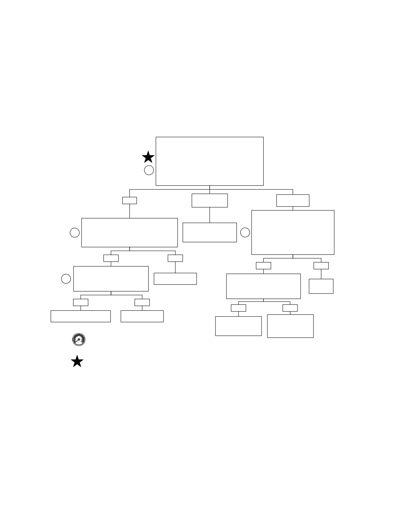
TMAP Diagnostics: DTC P0107, P0108, P0112, P0113 (Part 2 of 4)
Continued from TMAP Diagnostics: P0107, P0108
(Part 1 of 2).
Disconnect connector [80B] and check the 5 volt
reference supply at the TMAP Sensor connector [80B].
With Ignition Switch in IGNITION position, measure
2
voltage between terminal “3” (R/W) and terminal “1”
(BK/GY).
Is voltage approximately 5.0 volts?
NO.
NO.
YES
Greater than 6V.
Less than 4.5V.
Connect Breakout Box to connector [78B]
leaving ECM disconnected. Check
Disconnect connector [78B].
continuity between TMAP connector [80B]
OPEN CHECK: Measure resistance between
Locate short to 12 volts on
terminal “3” and Breakout Box terminal
2
TMAP Connector [80B] terminal “4” and Breakout
(R/W) wire in wire harness.
2
“68”. Then measure continuity between
Box terminal “24”.
Repair as necessary.
TMAP connector [80B] terminal “1” and
Is resistance less than 1.0 ohm?
Breakout Box terminal “62”.
Resistance less than 1.0 ohm?
YES
NO
YES
NO
SHORT CHECK: Measure resistance
between TMAP connector terminal “4”
Locate and repair
2
Check resistance between TMAP
and Ground.
open on (V/W) wire.
connector [80B] terminal “3” and
Repair
Is resistance greater than 1 megohm?
Breakout Box terminal “68”.
open wire.
Is resistance greater than 1 megohm?
YES
NO
YES
NO
Replace TMAP Sensor. See
Locate and repair
Touring Service Manual.
grounded (V/W) wire.
Locate and repair
Replace ECM.
short between
Reprogram and learn
(R/W) and (BK/GY)
password.
Clear codes using speedometer self diagnostics. See 4.6
wires.
SPEEDOMETER SELF DIAGNOSTICS. Confirm proper
operation with no check engine lamp.
At some point in the flow chart you may be instructed to jump directly to a the
box with the bold asterisk. Disregard the asterisk (but not the instruction box)
fc01031_en
if your normal progression through the chart brings you to this location.
4-82 2008 Touring Diagnostics: Engine Management
HOME
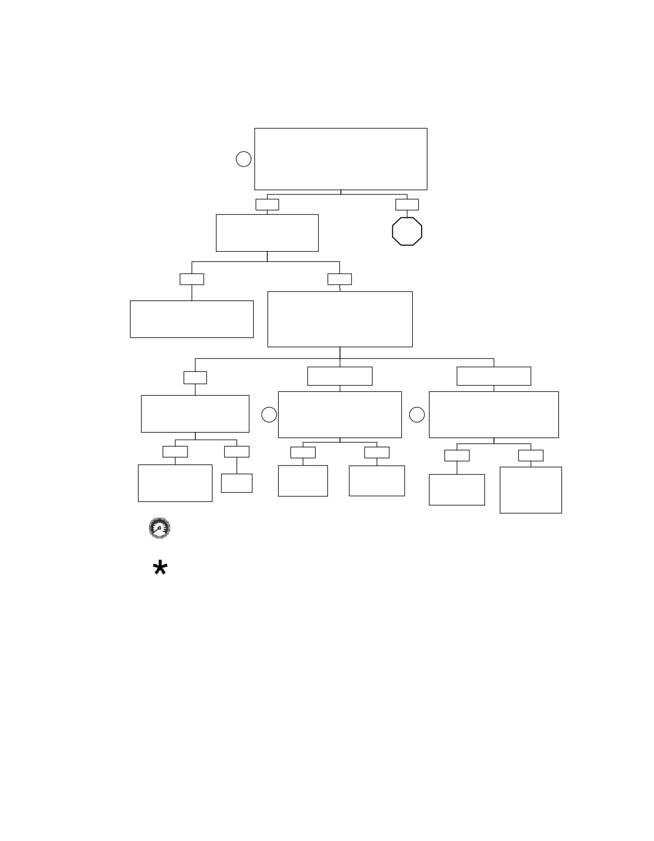
TMAP Diagnostics: DTC P0107, P0108, P0112, P0113 (Part 3 of 4)
Connect Breakout Box to connector [78B] leaving
ECM disconnected. With engine at room temperature
60-90o F (16-32o C), use a DVOM to measure
3
resistance across terminals “49” and “62” on Breakout
Box. If engine is warm, refer to Table 4-27.
Is resistance between 2.0k ohms and 5.0k ohms at
room temperature?
YES
NO
Connect ECM to Breakout Box.
Perform Section 4.8 WIGGLE
STOP
TEST to check for intermittents.
Intermittents present?
Go to TMAP Diagnostics: DTC
P0107, P0108, P0112, P0113
(Part 4 of 4).
YES
NO
Disconnect TMAP Sensor connector [80].
While wiggling harness, perform
Turn Ignition Switch to IGNITION position.
steps marked by BOLD ASTERISKS
Using a DVOM, measure the voltage between
under TMAP Diagnostics (Part 2 of 2)
ECM terminal “49” (positive) and terminal “62”
and repair as necessary.
(negative) on Breakout Box.
Is voltage measured approximately 5.0 volts?
NO.
NO.
YES
Less than 4.7 volts.
Greater than 5.3 volts.
With TMAP Sensor disconnected,
Unplug ECM leaving Breakout Box
Replace TMAP Sensor, clear
disconnect ECM from Breakout Box.
connected at vehicle harness. Measure
codes and road test.
3
Measure resistance between Breakout
3
voltage between Breakout Box terminal
Did check engine lamp illuminate
Box terminal “49” and terminal “73”.
“49” and terminal “73”.
and set DTC P0112 or P0113?
Is resistance less than 1 megohm?
Is voltage 0.0 volt?
YES
NO
YES
NO
YES
NO
Install original TMAP
Repair short to
Replace ECM.
Examine TMAP
Sensor, replace ECM,
System
ground on
Reprogram and
Replace ECM.
signal wire
perform password
OK.
(LGN/Y) wire.
learn password.
Reprogram and
(LGN/Y) for short
learning and road test.
learn password.
to voltage and
repair.
Clear codes using speedometer self diagnostics. See
4.6 SPEEDOMETER SELF DIAGNOSTICS. Confirm
proper operation with no check engine lamp.
At some point in the flow chart you may be instructed to jump directly
to a the box with the bold asterisk. Disregard the asterisk (but not the
fc01032_en
instruction box) if your normal progression through the chart brings
you to this location.
2008 Touring Diagnostics: Engine Management 4-83
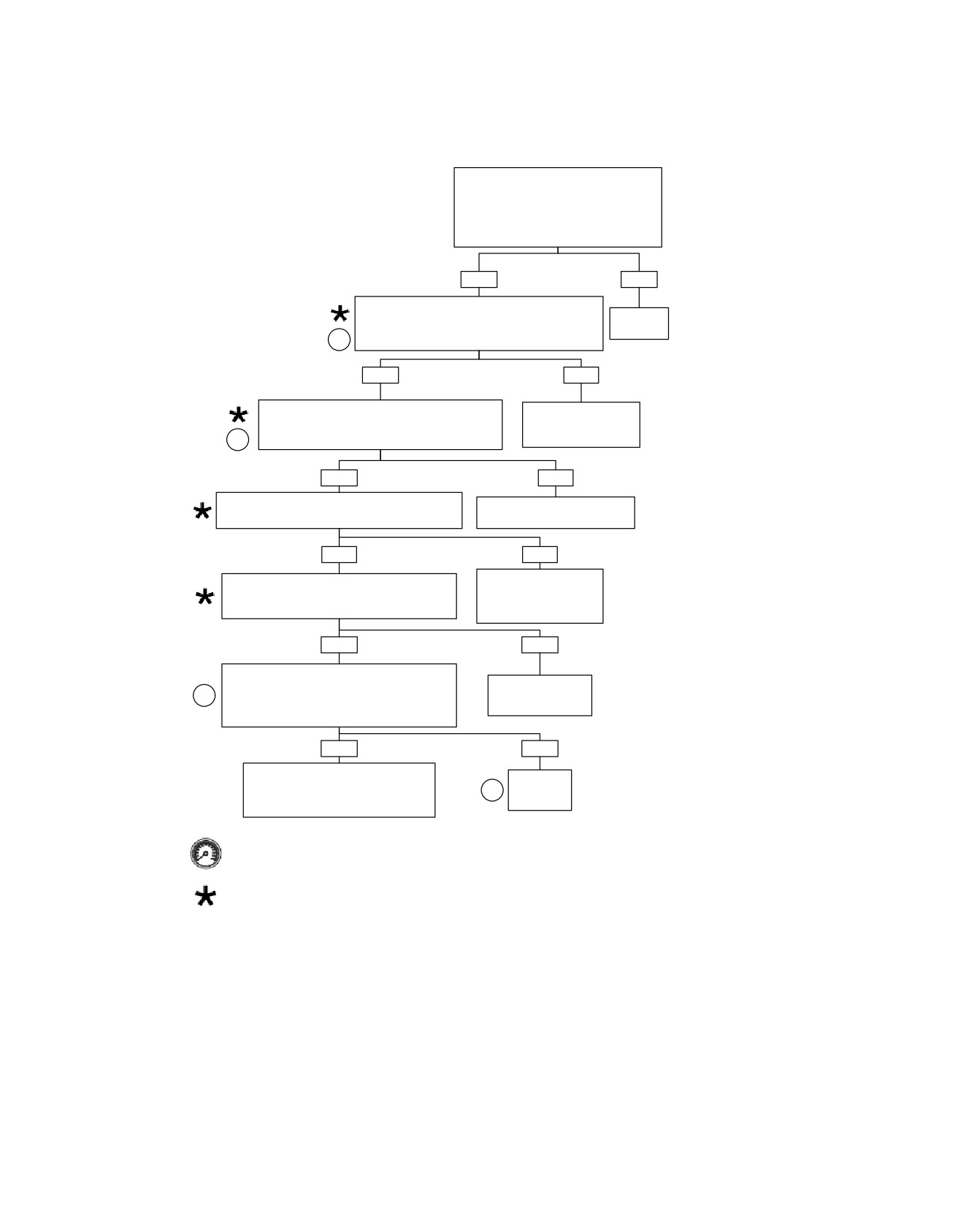
HOME
TMAP Diagnostics: DTC P0107, P0108, P0112, P0113 (Part 4 of 4)
Continued from TMAP Diagnostics: DTC
P0107, P0108, P0112, P0113 (Part 3 of 4).
Disconnect TMAP sensor connector [80B]
and examine for damage.
Is the connector OK?
YES
NO
Using a DVOM, measure the resistance between
TMAP sensor connector [80B] terminal “2” and ECM
Repair
terminal “49” on Breakout Box.
connector.
2
Is resistance less than 1.0 ohm?
YES
NO
Using a DVOM, measure the resistance between
Examine (LGN/Y) wire in
TMAP sensor connector [80B] terminal “1” and ECM
harness for open circuit
terminal “62” on Breakout Box.
2
and repair.
Is resistance less than 1.0 ohm?
YES
NO
Using a DVOM, measure the resistance between
Examine (BK/GY) wire in harness
ECM terminal “49” and terminal “62” on Breakout Box.
for open circuit and repair.
Is resistance greater than 1.0 megohm?
YES
NO
Examine (LGN/Y) and
Using a DVOM, measure the resistance between
(BK/GY) wires in harness
ECM terminal “49” on Breakout Box and Ground.
for short between these
Is resistance greater than 1.0 megohm?
two circuits and repair.
YES
NO
Remove TMAP Sensor and measure resistance
across the terminals of the TMAP Sensor directly.
Examine harness for
4
With sensor ambient temperature between 60-90o
short to ground and
F (16-32o C), is resistance between 2.0k ohms and
repair.
5.0k ohms?
YES
NO
Perform Section 4.8 WIGGLE TEST
Replace
on steps marked with a BOLD
5
TMAP
ASTERISK above to locate intermittents.
Sensor.
Repair as necessary.
Clear codes using speedometer self diagnostics.
See 4.6 SPEEDOMETER SELF DIAGNOSTICS.
Confirm proper operation with no check engine lamp.
At some point in the flow chart you may be instructed to jump directly to a the box with the bold
asterisk. Disregard the asterisk (but not the instruction box) if your normal progression through the
chart brings you to this location.
fc01033_en
4-84 2008 Touring Diagnostics: Engine Management
HOME
DTC P0117,
P0118
4.19
GENERAL
DIAGNOSTICS
ET Sensor
PART NUMBER
TOOL NAME
The ECM supplies and monitors a voltage signal terminal "51"
HD-41404-B
HARNESS CONNECTOR TEST KIT
to one side of the Engine Temperature (ET) sensor. The other
HD-48637
BREAKOUT BOX
side of the ET sensor is connected to a common sensor ground
terminal "61" of the ECM.
Diagnostic Tips
The ET sensor is a thermistor device, which means that at a
•
Once the engine is started, the ET voltage should rise
specific temperature it will have a specific resistance across
steadily.
its terminals. As this resistance varies, so does the voltage
•
An intermittent may be caused by a poor connection,
terminal "51".
rubbed through wire insulation or a wire broken inside the
•
At high temperatures, the resistance of the sensor is very
insulation.
low, which effectively lowers the signal voltage on terminal
Check the following conditions:
"51".
•
Poor connection: Inspect ECM and harness connector
•
At low temperatures, the resistance is very high, allowing
[78] for backed out terminals, improper mating, broken
the voltage to rise close to 5.0 volts.
locks, improperly formed or damaged terminals, poor ter-
The ECM monitors this voltage to compensate for various
minal-to-wire connection and damaged harness.
operating conditions.
•
Perform 4.8 WIGGLE TEST to locate intermittents: If
connections and harness check out OK, use a DVOM to
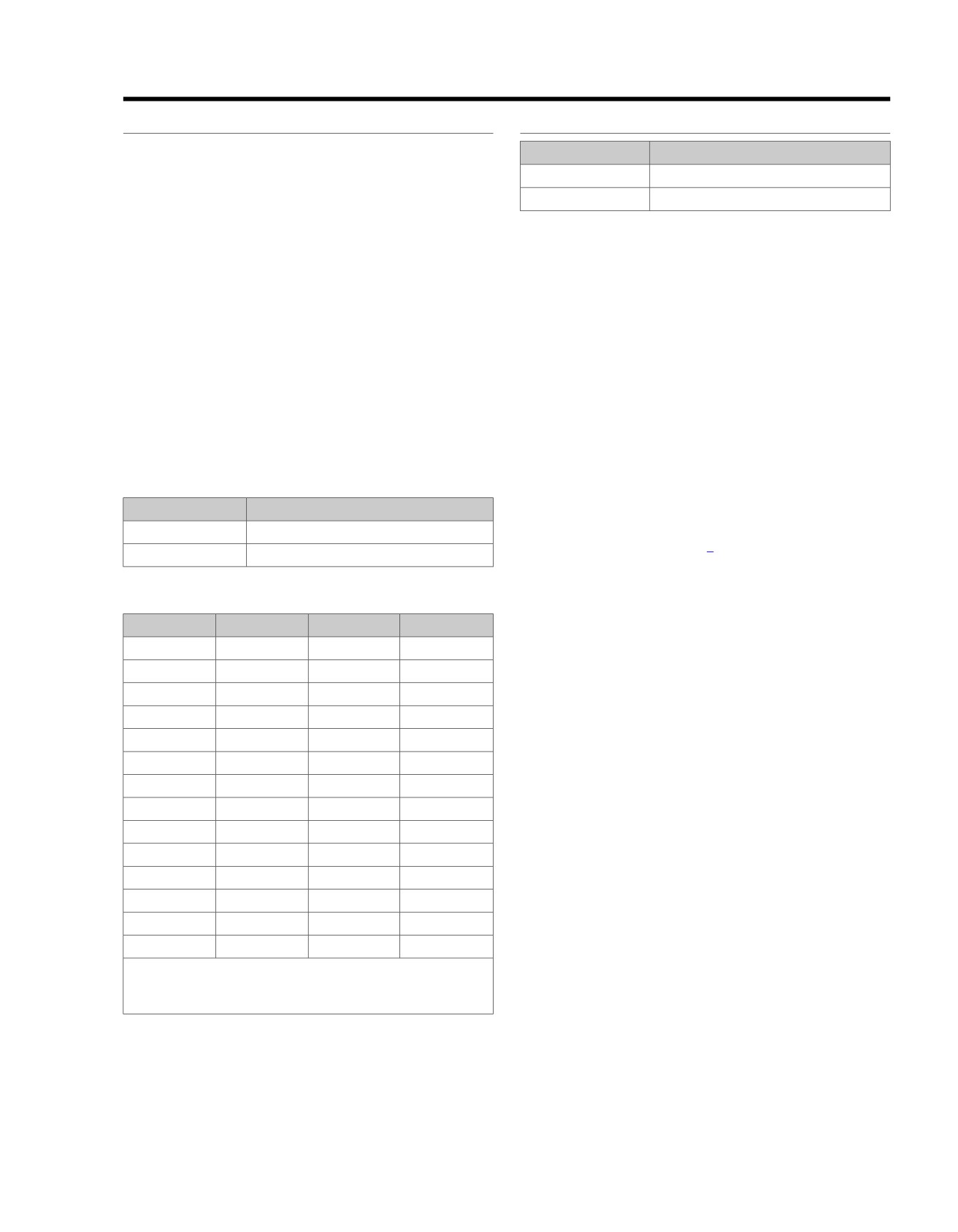
Table 4-29. Code Description
check the ET sensor voltage reading while moving related
DTC
DESCRIPTION
connectors and wiring harness. If the failure is induced,
the ET sensor voltage reading will change.
P0117
ET sensor voltage low
•
Shifted sensor: Refer to Table 4-30. This table may be
P0118
ET sensor open/high
used to test the ET sensor at various temperature levels
in order to evaluate the possibility of a shifted (out-of-cal-
Table 4-30. ET Sensor Table
ibration) sensor which may result in driveability problems.
TEMP °C
RESISTANCE
VOLTAGE
TEMP °F
NOTE
-20
28144
4.4
-4
All voltage and resistance values are approximate (± 20%).
-10
15873
4.0
14
Measure ET sensor resistance between ECM terminal "51"
and system ground ECM terminal "61".
0
9255
3.5
32
10
5571
3.0
50
Diagnostic Notes: ET Sensor
20
3457
2.4
68
Each reference number below correlates to a circled number
on the flow chart(s).
25
2750
2.1
77
1. Connect BREAKOUT BOX (Part No. HD-48637) to EFI
30
2205
1.8
86
wire harness only
(leave ECM disconnected). See
40
1442
1.3 or 4.1*
104
4.7 BREAKOUT BOX: EFI.
50
965
1.0 or 3.7*
122
2. Use HARNESS CONNECTOR TEST KIT (Part No. HD-
60
661
3.3
140
41404-B), purple pin probes and patch cords.
70
462
2.9
158
3. Use HARNESS CONNECTOR TEST KIT (Part No. HD-
80
329
2.5
176
41404-B), gray socket probes and patch cords.
90
238
2.1
194
4. Replace ET sensor. See Service Manual.
100
175
1.7
212
* Between 40-50°C the ECM changes scaling. Voltages for
ET sensor will shift scales in that range. This provides proper
sensor resolution for all temperatures.
2008 Touring Diagnostics: Engine Management 4-85