Harley Davidson 2008 Touring Models. Electrical Diagnostics Manual - page 12
HOME
Twist Grip Sensor
Engine
em00086
TMAP
Temp
Switch
Sensor
Throttle Control
Crank Pos.
[141A]
Actuator
Sensor
FUELPUMP
A
B
C D
[224A]
6
5
4
3
21
B D
Fuel Pump
[141B]
[224B]
[90A]
A B
[80A]
1
2
3 4
[91A]
[211A]
Assembly
Data
A B
(GY)
[90B]
1 2 3 4
6
5
4
3
2
1
in Tank
Link
[80B]
[79A]
12
1 2 3
6
5
4
3
2
1
[13B]
Fuel Tank
[79B]
12
[204A]
6
5
4
3
21
[211B]
Harness
1
4
[204B]
6
5
4
3
2
1
1
4
[13A]
Fuel
Y/GN
Electronic Control
Pump
Module
30(3)
87(5)
Fuse
[78A]
[78B]
(ECM)
86(1)
85(2)
15 Amp
Purge solenoid
20
20
GY/Y
System
MAXIFUSE
Exhaust actuator
21
21
V/O
[83B] [83A] Ignition Coil
Relay
40 Amp
Rear injector
23
23
GN/GY
[5B]
MAP sensor input
24
24
V/W
Y/GN
A
A
Power
B
A
GY/BE
B
B
Ion Sense
ECM
Front injector
28
28
W/Y
Y/BE
C
C
Coil Rear
BE/O
D
D
Coil Front
Fuse
Throttle actuator control HI
29
29
BK/O
Throttle actuator control LO
30
30
BK/PK
15 Amp
Ion sense
33
33
GY/BE
[84B]
[84A]
Battery
Throttle pos sensor 2
36
36
BN/R
Throttle pos sensor 1
37
37
BN/V
Front
Y/GN
A
A
Exhaust feedback
38
38
V/BE
[33B]
Y/W
B
B
Injector
Twist grip sensor 2
39
39
V/Y
[85B]
[85A]
Vehicle speed input
40
40
W/GN
Ignition
1
Fuse
R
2
Crank position sensor
43
43
BK
3
Y/GN
A
A
Rear
R/BK
Rear O2 sensor
46
46
PK/GN
B
B
15 Amp
GN/GY
Injector
Ignition
Intake air temperature
49
49
LGN/Y
Switch
5V sensor power 1
50
50
BN/O
[95B] [95A]
Engine
(33A)
Engine temperature
51
51
PK/Y
Control
12 V power
52
52
Y/GN
GY/Y
Fuse
Rear coil
53
53
Y/BE
Y/GN
15 Amp
Front coil
54
54
BE/O
Purge
Jiffy stand sensor
56
56
GN/BN
Solenoid
Twist grip sensor 1
59
59
BE/GN
5V sensor ground 1
61
61
BK/W
[65B] [65A]
5V sensor ground 2
62
62
BK/GY
Crank pos sensor (+)
63
63
R
BN/O
1
1
Vehicle speed ground
64
64
BK/Y
W/GN
2
2
Front O2 sensor
66
66
PK/O
BK/Y
3
3
5V sensor power 2
68
68
R/W
Vehicle Speed
Sensor
Serial data
69
69
LGN/V
Ground
73
73
BK/GN
[137B]
1 2
[138B]
1 2
[133B]
1
2 3
[179B]
43
2
1
Rear
Clean
Rear
Front
Jiffy
Active
Ground
O2
O2
Stand
Exhaust
Sensor
Sensor
Sensor
(HDI only)
(HDI only)
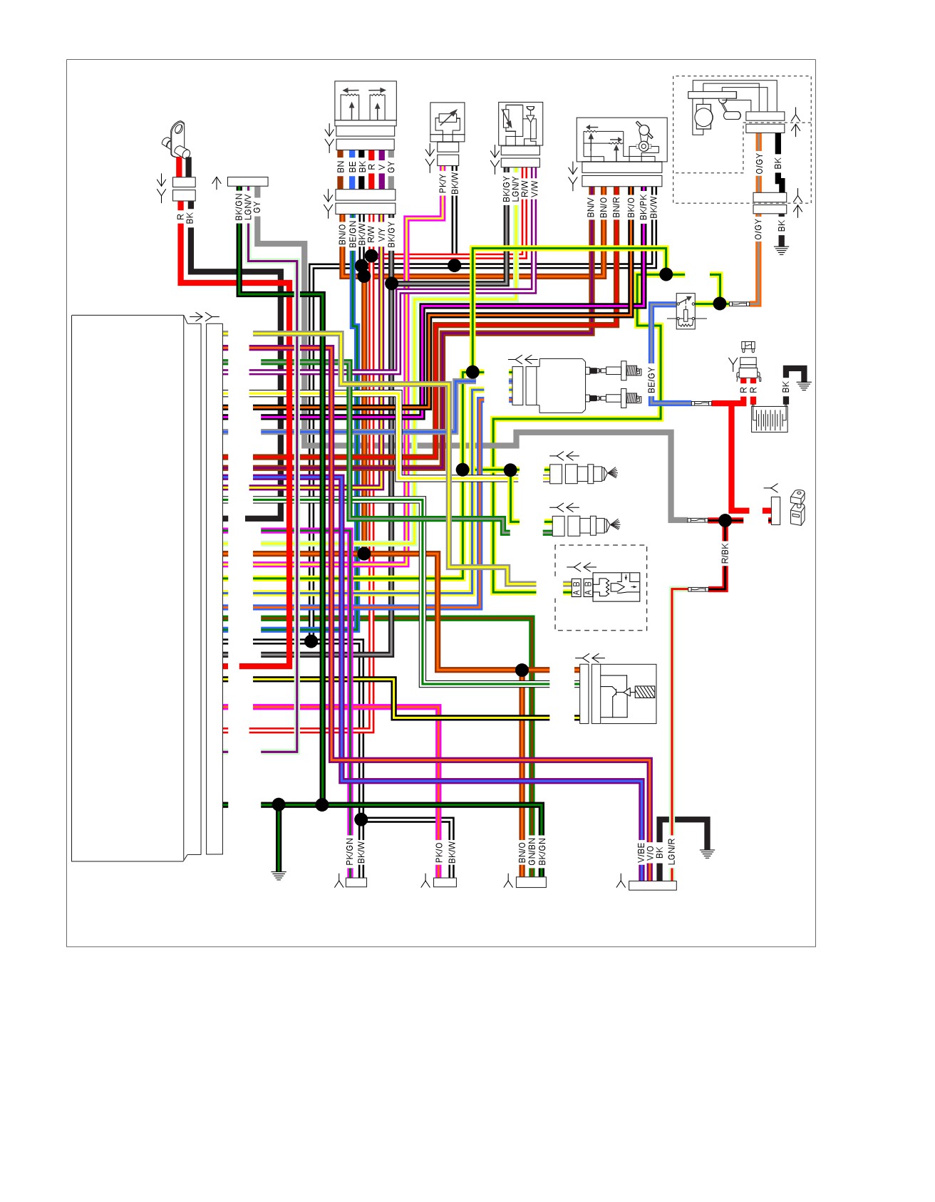
Figure 4-26. EFI Circuit
4-46 2008 Touring Diagnostics: Engine Management
HOME
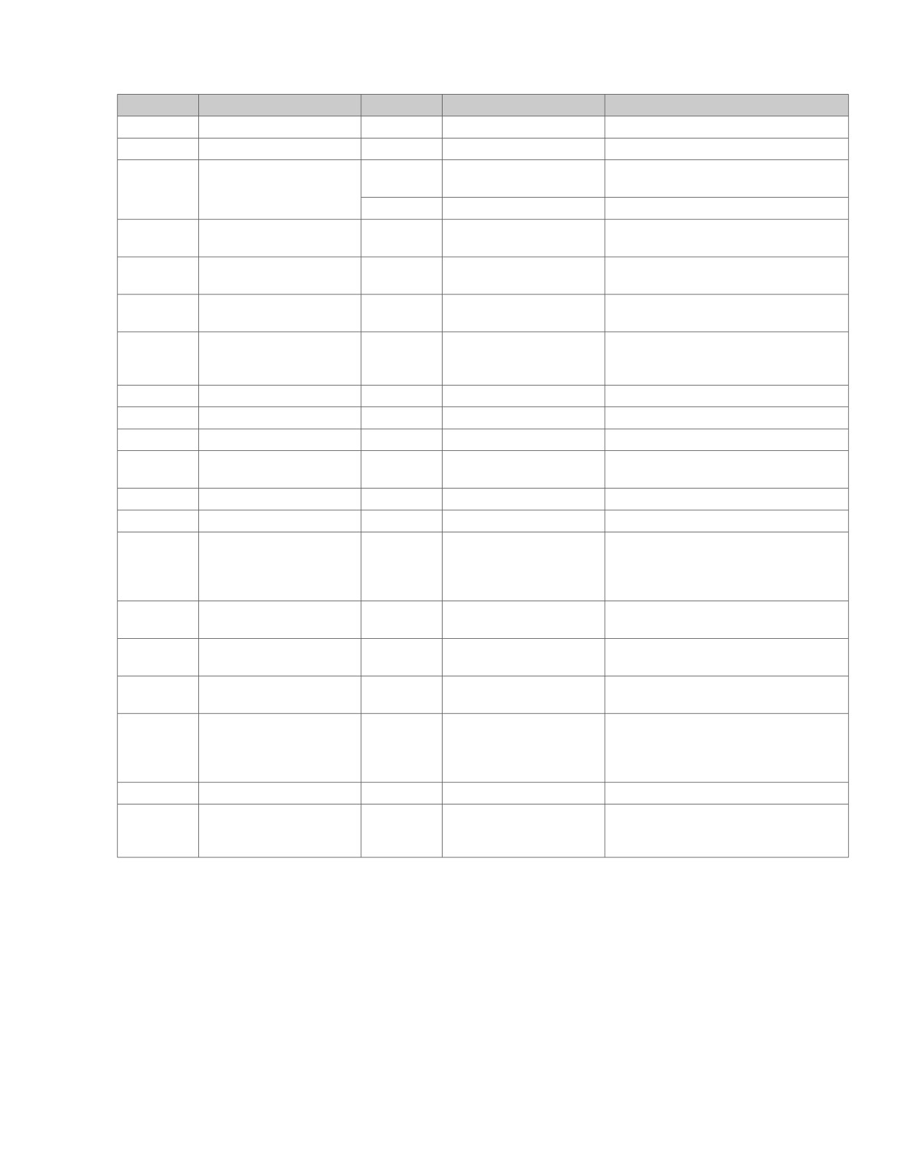
Table 4-17. Wire Harness Connectors
NO.
DESCRIPTION
MODEL
TYPE
LOCATION
[5]
MAXIFUSE
All
2-place Packard
Under left side cover
[13]
Fuel tank harness
All
4-place Multilock
Behind fuel tank (under seat)
[33]
Ignition switch
FLHT/C/U/
3-place Packard
Inner fairing - under radio (front of ignition
FLHTR
switch housing)
FLHR/C
3-place Packard
Under console
[65]
Vehicle Speed Sensor
All
3-place Delphi
Top of transmission case (under starter)
(VSS)
[78]
Electronic Control Module
All
73-place Delphi
Under seat
(ECM)
[79]
Crankshaft Position (CKP)
All
2-place Mini-Deutsch
Electrical caddie at bottom of lower frame
sensor
crossmember
[80]
T
emperature
Manifold
All
4-place Delphi
Top of induction module
Absolute Pressure (TMAP)
sensor
[83]
Ignition coil
All
4-place Delphi
Below fuel tank (left side)
[84]
Front injector
All
2-place Delphi
Below fuel tank (left side)
[85]
Rear injector
All
2-place Delphi
Below fuel tank (left side)
[90]
Engine T
emperature
(ET)
All
2-place Delphi
Back of front cylinder (left side)
sensor
[91]
Data link connector
All
4-place Deutsch
Under left side cover
[95]
Purge solenoid
All
2-place Delphi
Below fuel tank (left side)
[133]
Jiffy Stand Sensor
All
3-place Molex (black)
Domestic (not used): Electrical caddie
bottom of lower crossmember
HDI: Electrical caddie at bottom of lower
frame crossmember
[137]
O
2
sensor rear exhaust
All
2-place Amp (T
yco)
Under chrome starter cover
header
[138]
O
2
sensor front exhaust
All
2-place Amp (Tyco)
Back of cross brace front frame downtubes
header
(left side)
[141]
Fuel pump and fuel level
All
4-place Packard
Front right crankcase
sender
[179]
Active exhaust actuator
All
5-place Amp (Tyco)
Domestic (not used): Under right side
cover
HDI: Under right side cover (behind elec-
trical bracket)
[204]
T
wist Grip Sensor (TGS)
All
6-place Amp (T
yco)
Throttle control-handle bar (right side)
[211]
Throttle Control Actuator
All
6-place Molex
Right side of engine (Induction Module)
(TCA) and Throttle Position
(TP) sensor
2008 Touring Diagnostics: Engine Management 4-47
HOME
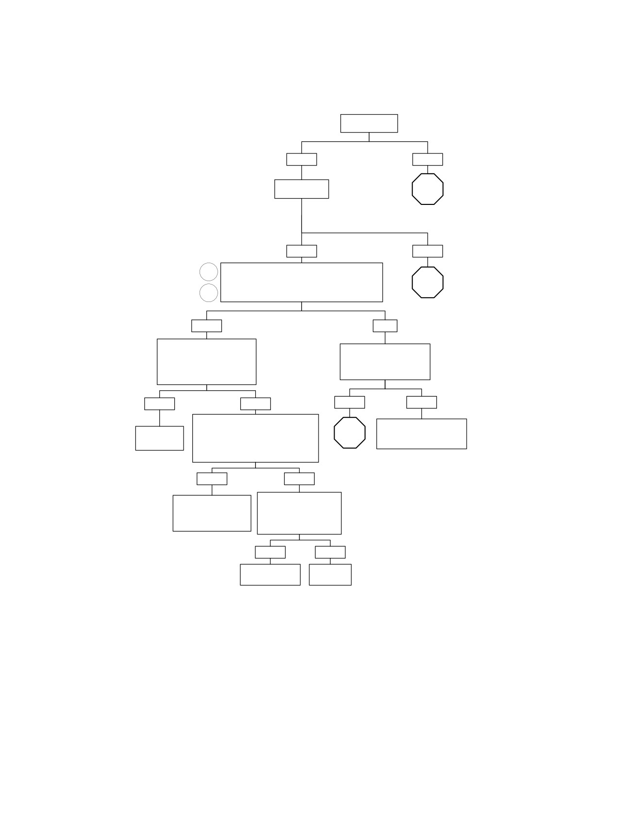
Fuel System Electrical Test (Part 1 of 4)
Is ECM Fuse
OK?
YES
NO
Is Fuel Pump
STOP
Fuse OK?
Go to 4.11 NO
ECM POWER.
YES
NO
1
Check for 12 volts at terminals “B” (+) and “D” (-) of
fuel pump connector [141B] during first 2-3 seconds
STOP
after Ignition Switch is in IGNITION position.
2
Is Battery voltage present?
Go to Fuel System
Electrical Test
YES
NO
(Part 4 of 4).
Check for corroded connections
Check for continuity to
or loose connectors between
chassis ground on [141B]
Fuel Pump and pump connector
terminal “D”.
[141B].
Is continuity present?
Poor connections found?
YES
NO
YES
NO
With Ignition Switch OFF, check for open
Locate and repair open on
pump circuit. Connect ohmmeter
STOP
(BK) wire between [141B]
Repair as
between connector terminal “B” and
necessary.
and Ground.
terminal “D” of connector [141A].
Is Continuity present?
Go to Fuel
System
Electrical Test
YES
NO
(Part 2 of 4).
Remove Fuel Pump.
Check pump
Check for continuity across
connections and repair
Fuel Pump terminals.
as required. If good,
Does meter read
replace Fuel Pump.
continuity?
YES
NO
Check for opening
Replace
fc01018_en
in wiring.
Fuel Pump.
4-48 2008 Touring Diagnostics: Engine Management
HOME
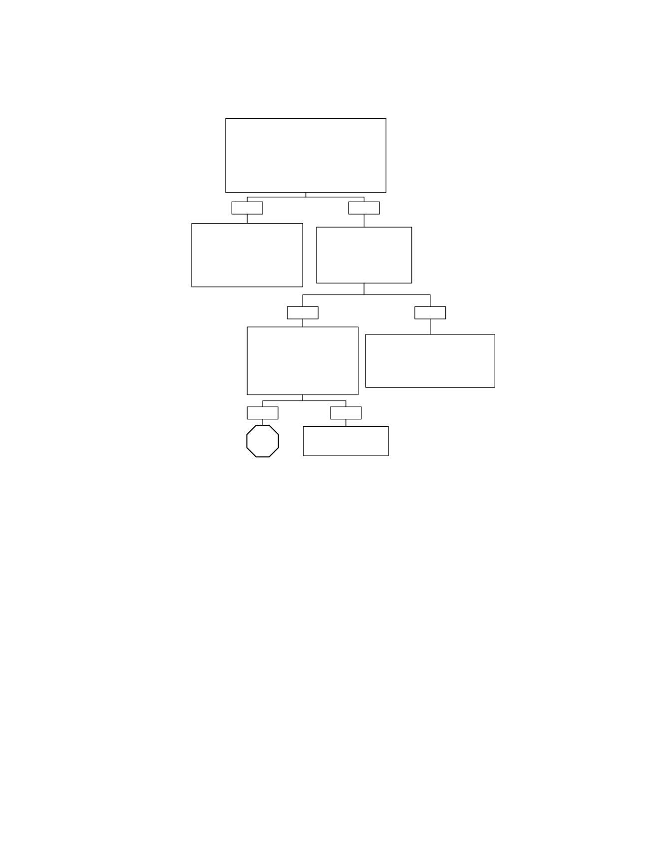
Fuel System Electrical Test (Part 2 of 4)
Continued from Fuel System Electrical Test
(Part 1 of 4).
Is 12 volts present at terminal “87” of System
Relay (with relay in place) during first two seconds
after Ignition Switch is in IGNITION position?
NOTE
Depending on relay used relay socket terminal
could be shown as “5” or “4C”.
YES
NO
Locate and repair open between
Is 12 volts present at terminal
terminal “B” of [141B] and terminal
“30" of System Relay?
“87" of System Relay.
NOTE
NOTE
Depending on relay used
Depending on relay used relay
relay socket terminal could be
socket terminal could be shown as
shown as “3” or “3D”.
“5” or “4C”.
YES
NO
With Ignition Switch in IGNITION
position and Engine Stop
Locate and repair open on (BE/GY) wire
Switch ON, is 12 volts present at
between ECM fuse and terminal “30” of
terminal “86” of System Relay?
System Relay.
NOTE
NOTE
Depending on relay used relay
Depending on relay used relay socket
socket terminal could be shown as
terminal could be shown as “3” or “3D”.
“1” or “4D”.
YES
NO
Locate and repair open on
STOP
(W/BK) wire to System
Relay.
Go to Fuel
System
Electrical Test
fc01019_en
(Part 3 of 4).
2008 Touring Diagnostics: Engine Management 4-49
HOME
Fuel System Electrical Test (Part 3 of 4)
Continued from Fuel System Electrical Test
(Part 2 of 4).
Probe System Relay connector terminal “85”
with a test light to 12 volts. Does test light
illuminate for 2 seconds after Ignition Switch is in
IGNITION position?
NOTE:
Depending on relay used relay socket terminal
could be shown as “2” or “3C”.
YES
NO
Probe Breakout Box terminal “27” with a test
3
Replace system
lamp connected to 12 volts.
relay.
Does test lamp illuminate for 2 seconds after
4
Ignition Switch is in IGNITION position?
YES
NO
Locate and repair open
Replace ECM. Reprogram
on (GN/O) wire.
and learn password.
fc01020_en
4-50 2008 Touring Diagnostics: Engine Management
HOME
Fuel System Electrical Test (Part 4 of 4)
Continued from Fuel System Electrical
Test (Part 1 of 4).
Check for intermittent short to chassis
ground on terminal “1” of connector [141B].
Is a short to ground present?
YES
NO
Reconnect fuel pump Connector [141] and Install fuel pressure gauge.
See 4.15 FUEL PRESSURE TEST. With fuel system intact and Battery
fully charged, remove Fuel Pump Fuse.
Repair short to
Connect DVOM across Fuel Pump Fuse terminals using probe.
Ground on (O/GY)
Place male positive probe in “4A” terminal. Turn Ignition Switch to
wire and replace Fuel
IGNITION position. With Fuel Pump running, check current and fuel
Pump Fuse.
pressure.
Is current draw under 4.5 amps and fuel pressure between 55-62 PSI
(380-425 kPA)?
YES
NO
Substitute known good relay for System Relay. Test
Replace fuse.
4
for current draw across Fuel Pump Fuse terminals.
Is current draw less than 4.5 amps?
YES
NO
Current draw now in range.
Replace Fuel
Replace System Relay and
Pump and replace Fuel
replace Fuel Pump Fuse.
Pump Fuse.
fc01021_en
2008 Touring Diagnostics: Engine Management 4-51
HOME
SYSTEM RELA
Y FAULT
4.14
seconds after the ignition is ON or the engine has stalled, or
GENERAL
immediately after the ignition is shut off.
System Relay
See Figure 4-27. With the Ignition Switch ON and the Engine
Table 4-18. Code Description
Stop Switch at RUN, the ECM will energize the system relay
DTC
DESCRIPTION
to complete the circuit to the in-tank fuel pump, ignition coil,
and fuel injectors. They will remain powered as long as the
P1001
System relay coil open/low
engine is cranking or running, and the ECM is receiving ignition
P1002
System relay coil high/shorted
reference pulses from the CKP sensor. If there are no reference
P1003
System relay contacts open
pulses, the ECM will de-energize the system relay within 2
P1004
System relay contacts closed
4-52 2008 Touring Diagnostics: Engine Management
HOME
ed01260
1
2
3
4
19
5
18
6
7
17
8
16
9
15
14
13
12
11
10
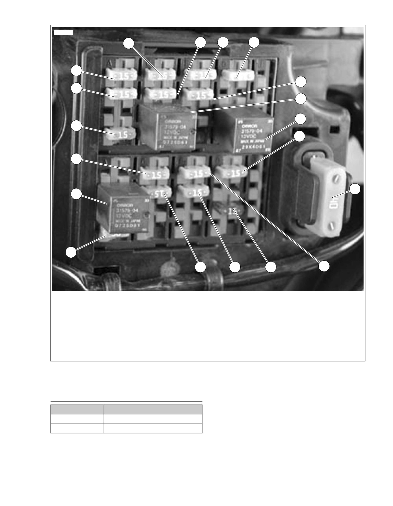
1. Accessory
11. Spare
2. Battery
12. Lights
3. P&A
13. Headlamp
4. Radio power/Siren (if equipped)
14. ABS (if equipped)
5. ECM power
15. Brake relay
6. System relay
16. Instruments
7. Start relay
17. Fuel pump
8. Engine control
18. Radio memory (if equipped)
9. MAXIFUSE
19. Brake/Cruise
10. Ignition
Figure 4-27. Fuse and Relay Locations
DIAGNOSTICS
1. Use HARNESS CONNECTOR TEST KIT (Part No. HD-
41404-B), gray pin probe and patch cord.
PART NUMBER
TOOL NAME
2. Connect BREAKOUT BOX (Part No. HD-48637) to ECM.
HD-41404-B
HARNESS CONNECTOR TEST KIT
See 4.7 BREAKOUT BOX: EFI.
HD-48637
BREAKOUT BOX
Diagnostic Notes
Each reference number below correlates to a circled number
on the flow chart(s).
2008 Touring Diagnostics: Engine Management 4-53
HOME
Twist Grip Sensor
em00093
Engine
Throttle
Temp.
TMAP
Control
Crank Position
Switch
Sensor
Actuator
Sensor
[224A]
654321
[224B]
654321
Data
[90A]
A
B
Link
[80A]
1234
[211A]
6
5
4
3
2
1
A
B
1234
[79A]
1 2
12
3
4
[90B]
[80B]
[211B]
6
5
4
3
2
1
1 2
[91A]
[204A]
6
54321
[79B]
[141A]
(GY)
[204B]
654321
FUELPUMP
AB CD
AB CD
Fuel Pump
Assembly In Tank
[141B]
Fuel Tank
[13B]
Harness
1234
1234
[13A]
Electronic
Control
[78A]
[78B]
Fuel
Module
Pump
87(5)
30(3)
Fuse
To
fuel
Purge solenoid
20
20
86(1)
15 Amp
gauge
Exhaust actuator
21
21
V/O
85(2)
[83B]
[83A]
Ignition Coil
System
Rear injector
23
23
GN/GY
MAXIFUSE
MAP sensor input
24
24
V/W
Relay
40 Amp
Y/GN
A
A
Power
Brake switch
25
25
R/BE
GY/BE
B
B
Ion sense
[5B]
System relay enable
27
27
GN/O
Y/BE
C
C
Coil rear
Front injector
28
28
W/Y
BE/O
D
D
Coil front
B A
Throttle by wires HI
29
29
BK/O
ECM
Throttle by wires LO
30
30
BK/PK
Fuse
BE/GY
(+)
(-)
Ion sense
33
33
GY/BE
Cruise/Resume/Accelerate
34
34
15 Amp
Cruise enable
35
35
Throttle pos. sensor-2
36
36
BN/R
[84B]
[84A]
Throttle pos. sensor-1
37
37
BN/V
Battery
Y/GN
A
A
Front
Exhaust feedback
38
38
V/BE
Twist grip sensor-2
39
39
V/Y
W/Y
B
B
Injector
[33B]
Vehicle speed input
40
40
W/GN
Ignition
[85B] [85A]
Fuse
Crank position sensor
43
43
BK
1
15 Amp
R
2
Y/GN
A
A
Rear
R/BK
3
Rear O2 sensor
46
46
PK/GN
GN/GY
B
B
Injector
Intake air temperature
49
49
LGN/Y
Ignition
5V sensor power-1
50
50
BN/O
Switch
Engine temperature
51
51
PK/Y
[95B] [95A]
Engine
[33A]
12V power
52
52
Y/GN
Control
Rear coil
53
53
Y/BE
Fuse
Front coil
54
54
BE/O
GY/Y
Y/GN
15 Amp
Jiffy stand sensor
56
56
GN/BN
Purge
Twist grip sensor-1
59
59
BE/GN
Solenoid
5V sensor ground-1
61
61
BK/W
5V sensor ground-2
62
62
BK/GY
[65B] [65A]
Crank pos. sensor (+)
63
63
R
Vehicle speed ground
64
64
BK/Y
BN/O
Vehicle
Front O2 sensor
66
66
PK/O
W/GN
Speed
5V sensor power-1
68
68
R/W
BK/Y
Sensor
Serial data
69
69
LGN/V
BK/W
12V battery
71
71
BE/GY
12V stop switch
72
72
W/BK
Ground
73
73
BK/GN
[1A]
3
6
Main
[1B]
3
6
Harness
To
accessory
fuse
[22B]
3
4
Right Hand
[121B]
Controls
[137B]
[138B]
[133B]
[179B]
[22A]
3
4
[121A]
12
12
123
54321
Rear
Rear
Front
Jiffy Stand
Active
Stop Lamp
O2 Sensor
O2 Sensor
Switch
Exhaust
Switch
(HDI only)
(HDI only)
Engine Stop Switch
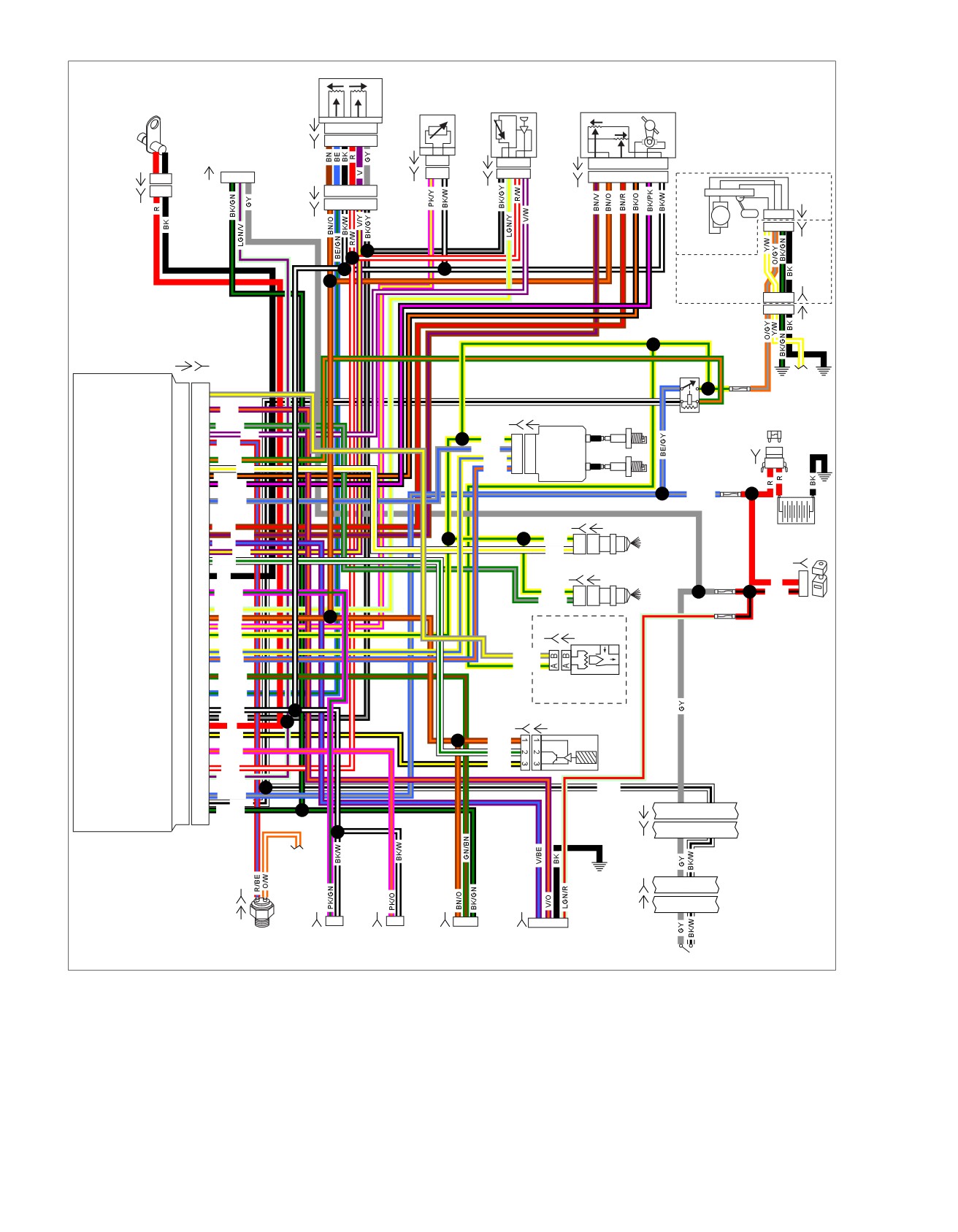
Figure 4-28. System Relay Circuit (FLHX, FLHT/C/U, FLTR)
4-54 2008 Touring Diagnostics: Engine Management

HOME
Table 4-19. Wire Harness Connectors
NO.
DESCRIPTION
TYPE
LOCATION
[1]
Main to interconnect harness
16-place Molex (black)
Inner fairing (right radio support
bracket)
[5]
MAXIFUSE
2-place Packard
Under left side cover
[13]
Fuel tank harness
4-place Multilock
Behind fuel tank (under seat)
[22]
Right handlebar switches
12-place Molex (black)
Inner fairing (fork stem nut lock plate)
[33]
Ignition switch
3-place Packard
Inner fairing (under radio)
[65]
Vehicle Speed Sensor (VSS)
3-place Delphi
Top of transmission case (under
starter)
[78]
Electronic Control Module (ECM)
73-place Delphi
Under seat
[79]
Crankshaft Position (CKP) sensor
2-place Mini-Deutsch
Electrical caddie at bottom of lower
frame crossmember
[80]
T
emperature Manifold Absolute Pres-
4-place Delphi
Top of induction module
sure (TMAP) sensor
[83]
Ignition coil
4-place Delphi
Below fuel tank (left side)
[84]
Front injector
2-place Delphi
Below fuel tank (left side)
[85]
Rear injector
2-place Delphi
Below fuel tank (left side)
[90]
Engine
Temperature (ET) sensor
2-place Delphi
Back of front cylinder (left side)
[91]
Data link connector
4-place Deutsch
Under left side cover
[95]
Purge solenoid
2-place Delphi
Below fuel tank (left side)
[121]
Rear brake light switch
Spade terminal
Bottom of rear frame downtub (right
side)
[133]
Jiffy Stand Sensor
3-place Molex (black)
Domestic (not used): Electrical caddie
bottom of lower crossmember
HDI: Electrical caddie at bottom of
lower frame crossmember
[137]
O
sensor rear exhaust header
2-place Amp (T
yco)
Under chrome starter cover
2
[138]
O
sensor front exhaust header
2-place Amp (Tyco)
Back of cross brace front frame down-
2
tubes (left side)
[141]
Fuel pump and fuel level sender
4-place Packard
Front right crankcase
[179]
Active exhaust actuator
5-place Amp (Tyco)
Domestic (not used): Under right side
cover
HDI: Under right side cover (behind
electrical bracket)
[204]
T
wist Grip Sensor (TGS)
6-place Amp (T
yco)
Throttle control-handle bar (right side)
[211]
Throttle Control Actuator (TCA) and
6-place Molex
Right side of engine (induction module)
Throttle Position (TP) sensor
2008 Touring Diagnostics: Engine Management 4-55
HOME
em00094
Twist Grip Sensor
Engine
Throttle
Temp.
TMAP
Control
Crank Position
Switch
Sensor
Actuator
Sensor
[224A]
654321
[224B]
654321
Data
[90A]
A
B
[80A]
1234
[211A]
6
5
4
3
2
1
Link
[79A]
1 2
12
3
4
[90B]
A
B
[80B]
1234
6
5
4
3
2
1
[211B]
1 2
[91A]
[204A]
6
54321
[79B]
[141A]
(GY)
654321
[204B]
FUEL
PUMP
ABCD
ABCD
Fuel Pump
[141B]
Assembly In Tank
Fuel Tank
[13B]
Harness
1234
1234
[13A]
Electronic
Control
Fuel
[78A] [78B]
Module
Pump
30(3)
87(5)
Fuse
To
Purge solenoid
20
20
85(2)
fuel
15 Amp
Exhaust actuator
21
21
V/O
86
gauge
[83B]
[83A]
(1)
Ignition Coil
System
Rear injector
23
23
GN/GY
MAXIFUSE
MAP sensor input
24
24
V/W
Relay
40 Amp
Brake switch
25
25
R/BE
Y/GN
A
A
Power
GY/BE
B
B
Ion sense
[5B]
System relay enable
27
27
GN/O
Y/BE
C
C
Coil rear
B A
Front injector
28
28
W/Y
BE/O
D
D
Coil front
ECM
Throttle by wires HI
29
29
BK/O
Throttle by wires LO
30
30
BK/PK
Fuse
BE/GY
(+)
(-)
Ion sense
33
33
GY/BE
15 Amp
GY
Throttle pos. sensor-2
36
36
BN/R
[84B]
[84A]
Throttle pos. sensor-1
37
37
BN/V
Battery
Y/GN
A
A
Front
Exhaust feedback
38
38
V/BE
Twist grip sensor-2
39
39
V/Y
W/Y
B
B
Injector
Vehicle speed input
40
40
W/GN
Ignition
[85B] [85A]
Fuse
Crank position sensor
43
43
BK
15 Amp
R
Rear O2 sensor
46
46
PK/GN
Y/GN
A
A
Rear
R/BK
GN/GY
B
B
Injector
Intake air temperature
49
49
LGN/Y
5V sensor power-1
50
50
BN/O
R/BK
Engine temperature
51
51
PK/Y
[95B] [95A]
Engine
12V power
52
52
Y/GN
Control
Rear coil
53
53
Y/BE
[33B]
I BA
GY/Y
Fuse
Front coil
54
54
BE/O
Y/GN
15 Amp
[33A]
ABCD
Jiffy stand sensor
56
56
GN/BN
Purge
Twist grip sensor-1
59
59
BE/GN
Solenoid
5V sensor ground-1
61
61
BK/W
Ignition
5V sensor ground-2
62
62
BK/GY
[65B] [65A]
Crank pos. sensor (+)
63
63
R
Switch
Vehicle speed ground
64
64
BK/Y
BN/O
Vehicle
Front O2 sensor
66
66
PK/O
W/GN
Speed
BK/Y
Sensor
5V sensor power-1
68
68
R/W
Serial data
69
69
LGN/V
W/BK
12V battery
71
71
BE/GY
12V stopt switch
72
72
W/BK
Ground
73
73
BK/GN
[22B]
3 4
[22A]
3 4
To
accessory
fuse
[121B]
[137B]
[138B]
[133B]
[179B]
[121A]
12
12
123
4321
Engine
Rear
Front
Jiffy Stand
Active
Stop
Rear
Switch
Switch
Stop Lamp
O2Sensor
O2Sensor
Exhaust
(HDI only)
(HDI only)
Switch
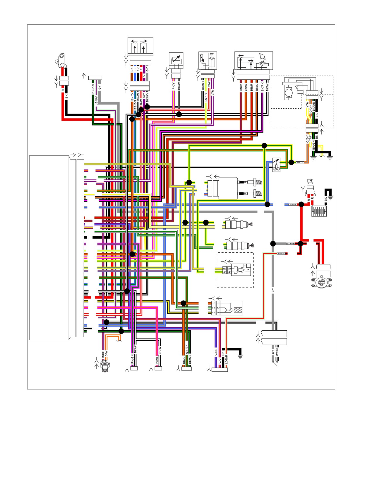
Figure 4-29. System Relay Circuit (FLHR/C/S)
4-56 2008 Touring Diagnostics: Engine Management

HOME
Table 4-20. Wire Harness Connectors
NO.
DESCRIPTION
TYPE
LOCATION
[5]
MAXIFUSE
2-place Packard
Under left side cover
[13]
Fuel tank harness
4-place Multilock
Behind fuel tank (under seat)
[22]
Right handlebar switches
6-place Molex (black)
Inside headlamp nacelle
[33]
Ignition switch
3-place Packard
Under console
[65]
Vehicle Speed Sensor (VSS)
3-place Delphi
Top of transmission case (under
starter)
[78]
Electronic Control Module (ECM)
73-place Delphi
Under seat
[79]
Crankshaft Position (CKP) sensor
2-place Mini-Deutsch
Electrical caddie at bottom of lower
frame crossmember
[80]
T
emperature Manifold Absolute Pres-
4-place Delphi
Top of induction module
sure (TMAP) sensor
[83]
Ignition coil
4-place Delphi
Below fuel tank (left side)
[84]
Front injector
2-place Delphi
Below fuel tank (left side)
[85]
Rear injector
2-place Delphi
Below fuel tank (left side)
[90]
Engine
Temperature (ET) sensor
2-place Delphi
Back of front cylinder (left side)
[91]
Data link connector
4-place Deutsch
Under left side cover
[95]
Purge solenoid
2-place Delphi
Below fuel tank (left side)
[121]
Rear brake light switch
Spade terminal
Bottom of rear frame downtub (right
side)
[133]
Jiffy Stand Sensor
3-place Molex (black)
Domestic (not used): Electrical caddie
bottom of lower crossmember
HDI: Electrical caddie at bottom of
lower frame crossmember
[137]
O
sensor rear exhaust header
2-place Amp (T
yco)
Under chrome starter cover
2
[138]
O
sensor front exhaust header
2-place Amp (Tyco)
Back of cross brace front frame down-
2
tubes (left side)
[141]
Fuel pump and fuel level sender
4-place Packard
Front right crankcase
[179]
Active exhaust actuator
5-place Amp (Tyco)
Domestic (not used): Under right side
cover
HDI: Under right side cover (behind
electrical bracket)
[204]
T
wist Grip Sensor (TGS)
6-place Amp (T
yco)
Throttle control-handle bar (right side)
[211]
Throttle Control Actuator (TCA) and
6-place Molex
Right side of engine (induction module)
Throttle Position (TP) sensor
2008 Touring Diagnostics: Engine Management 4-57
HOME
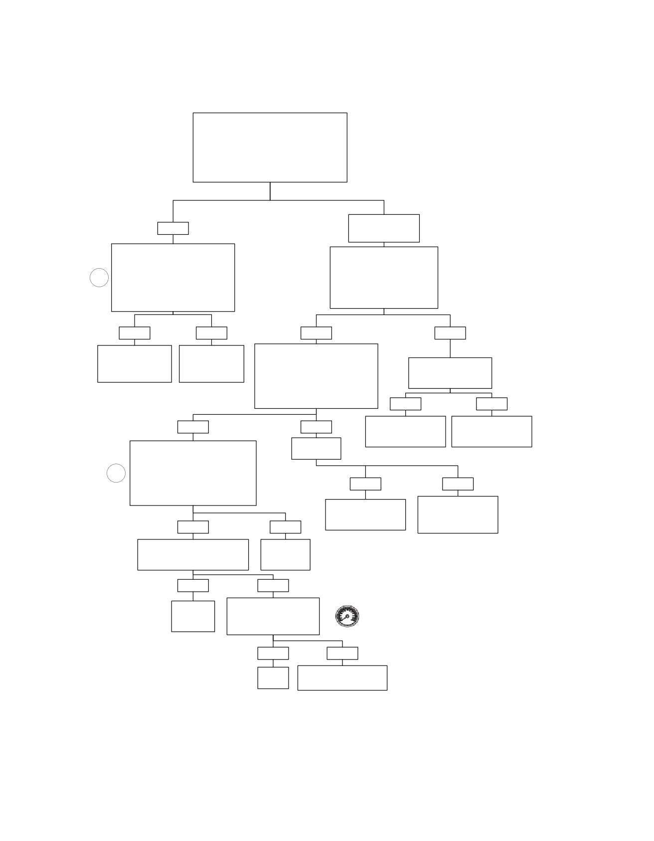
System Relay Fault (Part 1 of 3)
With relay in, check for battery voltage at terminal
“87” of system relay during first 2-3 seconds
after Ignition Switch is in IGNITION position.
NOTE:
Depending on relay used relay socket terminal
could be shown as “5” or “4C”.
Is Battery voltage (10-13 volts) present for 2-3
seconds after system is activated?
NO.
YES
No voltage or voltage
always present.
System Relay OK. With relay out,
Check for 10-13 volts at
measure resistance between
terminal “30” of the System Relay.
terminal “87” of the System Relay and
NOTE
terminal “A” of connector [83B].
1
Depending on relay used relay
NOTE
socket terminal could be shown
Depending on relay used relay socket
as “3” or “3D”.
terminal could be shown as “5” or “4C”.
Is voltage present?
Is resistance less than 0.5 ohm?
YES
NO
YES
NO
Recheck connections.
Locate and repair
With ignition active, check for
Wiggle harness while
connection or
10-13 volts at terminal “86” of
Check for continuity to
repeating test. Repair
open on (Y/GN)
the System Relay.
ground on (BE/GY) wire.
intermittent.
wire.
NOTE
Depending on relay used relay socket
Is continuity present?
terminal could be shown as “1” or “4D”.
Is voltage present?
YES
NO
Locate and repair short
Locate and repair
YES
NO
to ground and replace
open between System
ECM Fuse.
Fuse and System Relay.
Is Ignition
Measure resistance between terminal
Fuse shorted?
“85” of System Relay and terminal “27”
on Breakout Box.
2
NOTE
Depending on relay used relay socket
YES
NO
terminal could be shown as “2” or “3C”.
Is resistance less than 0.5 ohm?
Locate and repair
Locate and repair short
open on (W/BK) wire
to ground and replace
between connector [22]
Ignition Fuse.
YES
NO
and System Relay.
Check for continuity to ground
Locate and
on terminal “27” of Breakout Box.
repair open on
Is continuity present?
(GN/O) wire.
YES
NO
Replace System Relay.
Clear codes using speedometer self diagnostics.
Locate and
Does Fuel Pump run for the
See 4.6 SPEEDOMETER SELF DIAGNOSTICS.
repair short
first 2 seconds after system
Confirm proper operation with no check engine
to ground.
is active?
lamp.
YES
NO
System
Replace ECM. Reprogram
OK.
and learn password.
fc01022_en
4-58 2008 Touring Diagnostics: Engine Management
HOME
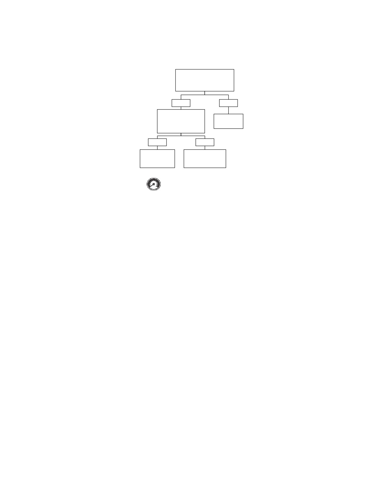
System Relay Fault (Part 2 of 3)
Remove System Relay.
Check for voltage on
terminal “27” of Breakout Box.
Is Voltage present?
YES
NO
Remove Breakout Box
connector from ECM.
Replace
Is voltage still present on
System Relay.
terminal “27”?
YES
NO
Locate and repair
Replace ECM.
short to voltage
Reprogram and learn
on (GN/O) wire.
password.
Clear codes using speedometer self diagnostics. See
4.6 SPEEDOMETER SELF DIAGNOSTICS. Confirm
proper operation with no check engine lamp.
fc01023_en
2008 Touring Diagnostics: Engine Management 4-59
HOME
System Relay Fault (Part 3 of 3)
Check connectors [13] (except FLHR/C/S) and [141] for
corrosion, damaged terminals, improper wire location, or
poor ground connection.
Do any of these conditions exist?
YES
NO
Condition: Fuel Pump continues to run
with Ignition Switch OFF.
Repair.
Remove System Relay.
Does pump continue to run?
YES
NO
Locate and repair short
Replace
to voltage on (Y/GN)
System Relay.
wire.
fc01024_en
4-60 2008 Touring Diagnostics: Engine Management
HOME
FUEL PRESSURE
TEST
4.15
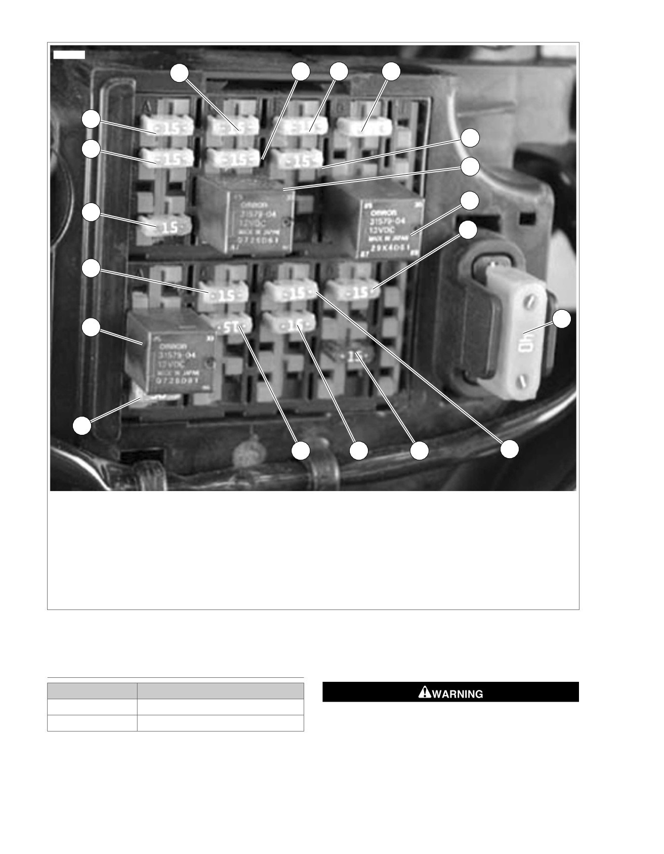
See Figure 4-30. The fuel pump fuse is located on the fuse
GENERAL
block behind the left side cover. The fuel pump can be turned
PART NUMBER
TOOL NAME
on with the DIGITAL TECHNICIAN (Part No. HD-44750) or by
applying battery voltage to the fuel pump fuse.
HD-44750
DIGITAL TECHNICIAN
Improper fuel system pressure may contribute to one of the
The fuel pump delivers fuel to the fuel line, to a cavity in the
following conditions:
induction module that supplies the fuel injectors and to the
pressure regulator, where the system pressure is controlled.
•
Cranks, but won't run.
Excess fuel pressure is bypassed to the fuel tank through the
•
Cuts out (may feel like ignition problem).
pressure regulator.
•
Hesitation, loss of power or poor fuel economy.
2008 Touring Diagnostics: Engine Management 4-61
HOME
ed01260
1
2
3
4
19
5
18
6
7
17
8
16
9
15
14
13
12
11
10
1. Accessory
11. Spare
2. Battery
12. Lights
3. P&A
13. Headlamp
4. Radio power/Siren (if equipped)
14. ABS (if equipped)
5. ECM power
15. Brake relay
6. System relay
16. Instruments
7. Start relay
17. Fuel pump
8. Engine control
18. Radio memory (if equipped)
9. MAXIFUSE
19. Brake/Cruise
10. Ignition
Figure 4-30. Fuse and Relay Locations
TESTING
1. Remove left side cover.
PART NUMBER
TOOL NAME
HD-41182
FUEL PRESSURE GAUGE
To prevent spray of fuel, purge system of high-pressure
HD-44061
FUEL PRESSURE GAUGE ADAPTER
fuel before supply line is disconnected. Gasoline is
extremely flammable and highly explosive, which could
The fuel pressure gauge allows for fuel injector and fuel system
result in death or serious injury. (00275a)
pressure diagnosis. A special adapter allows the gauge to be
attached to the external fuel supply line.
4-62 2008 Touring Diagnostics: Engine Management
HOME
2. Purge fuel supply line of high pressure fuel.
10. Open and close throttle to change engine speed. Note
pressure gauge reading. Fuel pressure should remain
a. See Figure 4-30. Unplug fuel pump fuse from fuse
steady at 55-62 psi (380-425 kPa).
block.
11. Turn engine off. Position air bleed tube in a suitable con-
b. Start engine and allow vehicle to run.
tainer. Open air bleed petcock to relieve fuel system
c. When engine stalls, operate starter for three seconds
pressure and purge pressure gauge of gasoline.
to remove any remaining fuel from fuel line.
Gasoline can drain from the adapter when gauge is
Gasoline can drain from quick-connect fitting when
removed. Gasoline is extremely flammable and highly
removing fuel line. Gasoline is extremely flammable and
explosive, which could result in death or serious injury.
highly explosive, which could result in death or serious
Wipe up spilled fuel immediately and dispose of rags in a
injury. Wipe up spilled fuel immediately and dispose of
suitable manner. (00254a)
rags in a suitable manner. (00267a)
12. Remove fuel pressure gauge from the adapter. Install
3. Pull up on chrome sleeve of quick-connect fitting (fitting
protective cap over Schroeder valve.
on left side of fuel tank) and pull down on fuel supply line
to disconnect.
NOTE
Gasoline can drain from the fuel line and adapter when
The next step requires two fuel pressure gauge adapters.
removed. Gasoline is extremely flammable and highly
Failure to use two adapters may cause the fuel line to twist,
explosive, which could result in death or serious injury.
resulting in a broken fuel line or fuel line fitting.
Wipe up spilled fuel immediately and dispose of rags in a
4. Attach fuel line to gauge assembly.
suitable manner. (00255a)
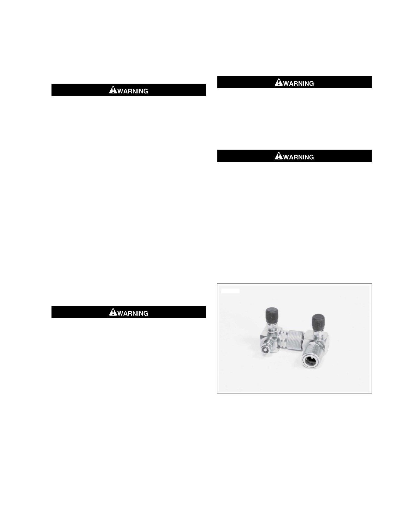
a. See Figure 4-32. Install a second adapter in series
13. Pull up on sleeve of quick-connect fitting and remove fuel
with the first.
supply line from fuel pressure gauge adapter. Release
adapter from fuel tank in the same manner.
b. See Figure 4-32. Pull up on chrome sleeve of fuel
tank quick-connect fitting and insert neck of FUEL
14. Pull up on chrome sleeve of fuel tank quick-connect fitting
PRESSURE GAUGE ADAPTER (Part No. HD-44061)
and insert neck of fuel supply line fitting. While pushing
into fuel supply line.
up on bottom of fuel supply line fitting, pull down on
chrome sleeve until it "clicks" into the locked position. Tug
c. While pushing up on bottom of adapter, pull down on
on fuel supply line to be sure that it is secure.
chrome sleeve until it "clicks" into the locked position.
Tug on adapter to be sure it is secure.
15. Install right side cover and saddlebag.
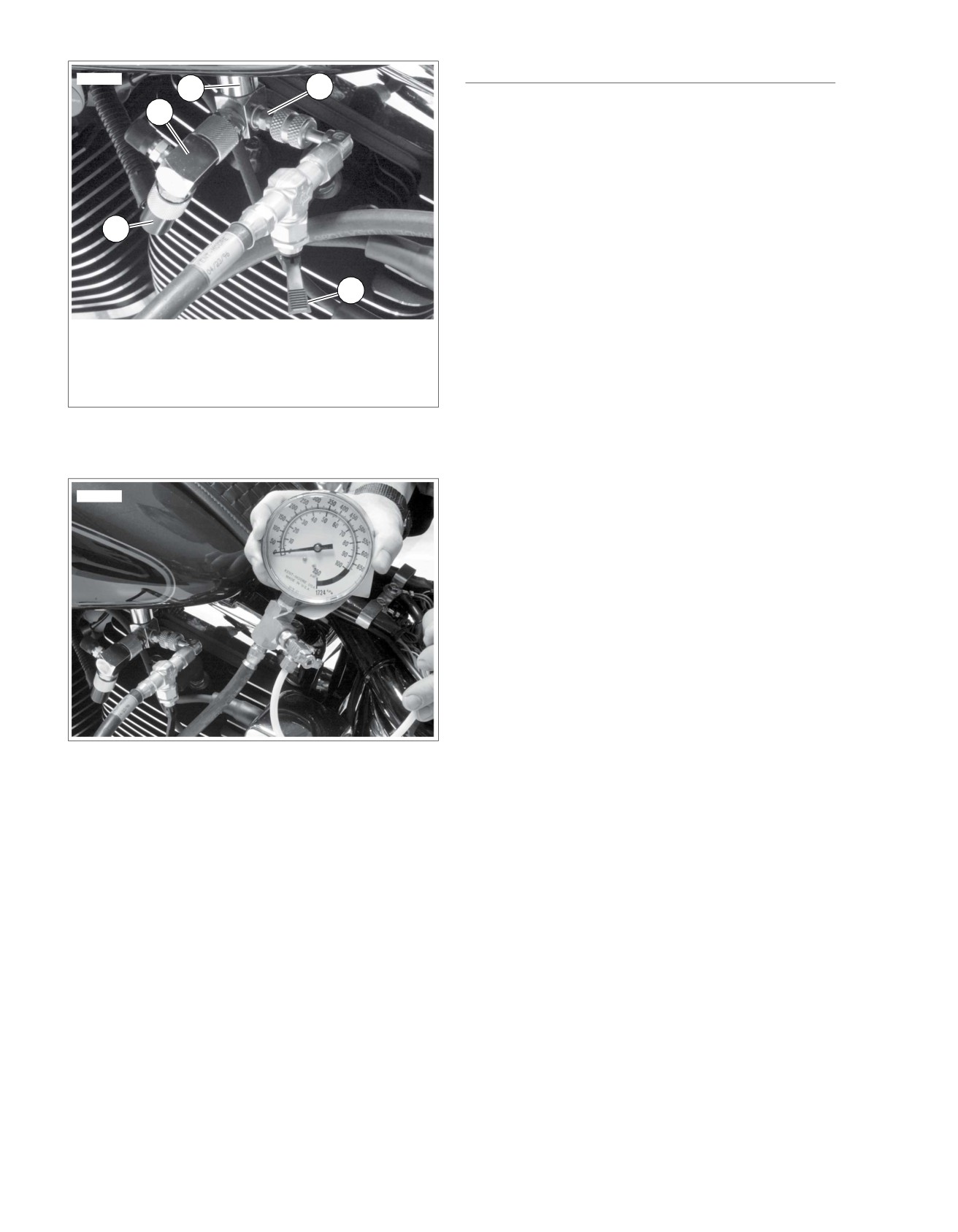
d. See Figure 4-33. In the same manner, install fuel
supply line fitting into adapter quick-connect fitting
ed02016
(4). Tug on fuel supply line to be sure that it is secure.
To prevent spray of fuel, be sure quick-connect fittings
are properly mated. Gasoline is extremely flammable and
highly explosive, which could result in death or serious
injury. (00268a)
5. Verify that fuel valve and air bleed petcock on FUEL
PRESSURE GAUGE (Part No. HD-41182) are closed.
6. See Figure 4-32. Remove protective cap from free end of
fuel pressure gauge adapter. Connect fuel pressure gauge
to Schroeder valve. Tighten fitting securely.
7. See Figure 4-30. Install fuel pump fuse.
Figure 4-31. Fuel Pressure Gauge Adapters
8. Start and idle engine to pressurize fuel system. Open fuel
valve to allow fuel to flow down hose of pressure gauge.
9. Position clear air bleed tube in a suitable container. Open
and close air bleed petcock to purge gauge and hose of
air. Repeat this step several times until only solid fuel
(without bubbles) flows from air bleed tube. Close petcock.
2008 Touring Diagnostics: Engine Management 4-63
HOME
DIAGNOSTICS
ed02017
3
4
Diagnostic Notes
2
Each reference number below correlates to a circled number
on the flow chart(s).
1. See Fuel Pressure Regulator, Removal/Installation in the
Service Manual.
2. If fuel system has pressure, but it is less than specification,
check for the following conditions.
1
a. The amount of fuel to the injectors is within limits, but
pressure is too low. Also, hard starting and overall
poor performance condition may exist.
5
b. Restricted fuel flow causing pressure drop. However,
if pressure drop occurs only when driving, engine may
1. Fuel supply line
surge then lose power as pressure begins to drop
2. Adapter to fuel line
rapidly.
3. Adapter to fuel tank
4. Pressure adapter/Schroeder valve union
3. This condition may be identified when the fuel level is low
5. Fuel valve (closed position)
and the fuel pump is turned on for the first 2 seconds after
Figure 4-32. Fuel Line (Typical)
Ignition Switch is turned to IGNITION. A metallic ringing
sound can be heard as the high pressure fuel is sprayed
against the inside wall of the fuel tank.
ed02018
Figure 4-33. Fuel Pressure Gauge Installed (Typical)
4-64 2008 Touring Diagnostics: Engine Management
HOME
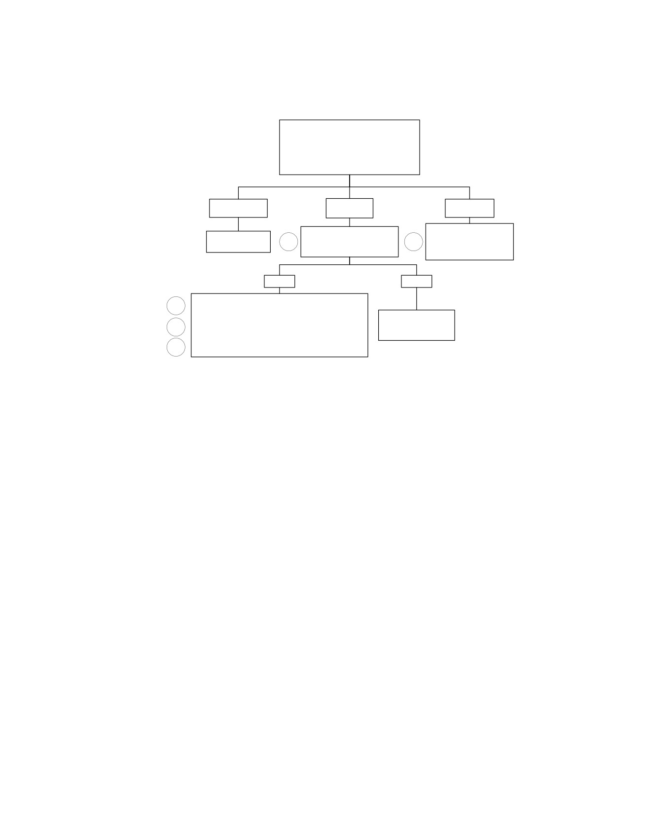
Fuel Pressure Test
Install fuel pressure gauge. See TESTING
under 4.15 FUEL PRESSURE TEST.
Start and idle engine. Open and close throttle
to change engine speed.
Does fuel pressure remain steady
at 55-62 PSI (380-425 kPa)?
YES
NO
NO
Steady pressure.
Low pressure.
High pressure.
Inspect check valve fitting
Check for restricted Fuel Filter
No trouble found.
assembly and Fuel Tank. If
2
or Fuel Pump Inlet Screen.
1
Review symptoms.
OK, replace faulty Fuel
Are filter and screen OK?
Pressure Regulator.
YES
NO
Check for restricted pressure line or flex hose between
1
Fuel Tank and test gauge.
If lines are OK, check for:
Replace Fuel Filter or
3
Restricted check valve fitting assembly.
clean Fuel Pump Inlet
Leaks inside Fuel Tank caused by faulty coupling hose or
Screen. Retest.
connection such as hose at filter or pump,
4
Check for a faulty Fuel Pressure Regulator.
fc01174_en
2008 Touring Diagnostics: Engine Management 4-65