Harley Davidson 2008 Touring Models. Electrical Diagnostics Manual - page 16
HOME
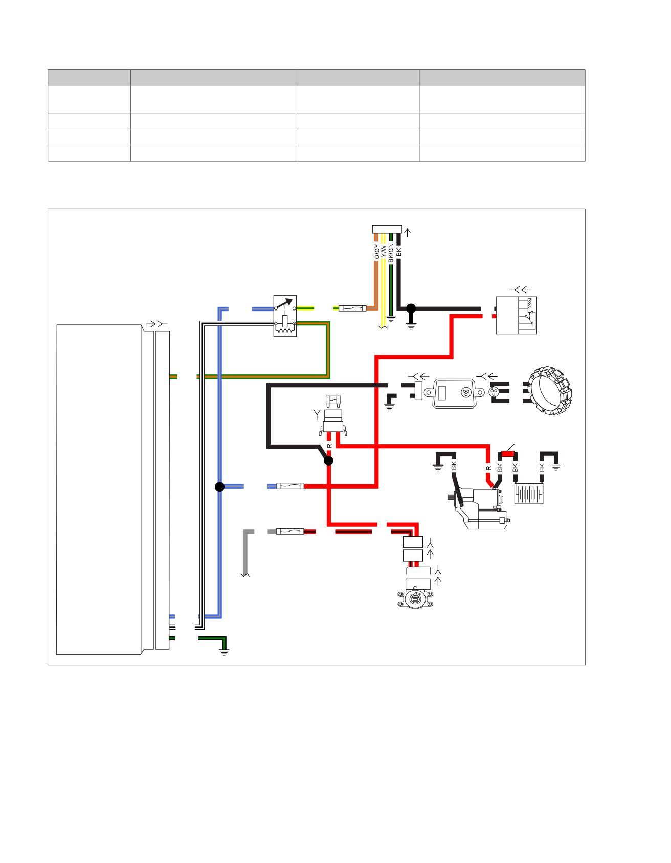
Table 4-46. Wire Harness Connectors
NO.
DESCRIPTION
TYPE
LOCATION
[1]
Main to interconnect harness
16-place Molex (black)
Inner fairing (right radio support
bracket)
[22]
Right handlebar switches
12-place Molex (black)
Inner fairing (fork stem nut lock plate)
[33]
Ignition switch
3-place Packard
Inner fairing (under radio)
[78]
Electronic Control Module (ECM)
73-place Delphi
Under seat
em00097
To fuel pump
1 2 3 4
[13A]
[126B] [126A]
15 Amp
86
(1)
Lighting
30(3)
87(5)
Electronic Control
BE/GY
Y/GN
BK
85
(2)
Relay
Module
[78A] [78B]
R
30
(3)
86(1)
85(2)
Fuel Pump
87A (4)
Fuse
87
(5)
To
System
fuel gauge
Relay
Stator
[77B]
[77A]
[47A]
[47B]
System relay enable
27
27
GN/O
BK
2
BK
BK
40 Amp
BK
1
MAXIFUSE
BK
[5B]
Voltage
B A
Regulator
Red
band
15 Amp
(+)
(-)
BE/GY
ECM Fuse
Battery
15 Amp
R
GY
R/BK
R/BK
Starter
Ignition
12
[222B]
Fuse
12
[222A]
ABC
[33B]
To
ABID
[33A]
engine
stop
switch
12V Battery
71
71
BE/GY
Ignition
12V Engine stop switch
72
72
W/BK
Switch
Ground
73
73
BK/GN
Figure 4-58. Battery Voltage Circuit Diagram (FLHR/C/S)
4-126 2008 Touring Diagnostics: Engine Management

HOME
Table 4-47. Wire Harness Connectors
NO.
DESCRIPTION
TYPE
LOCATION
[22]
Right handlebar switches
6-place Molex (black)
Inside headlamp nacelle
[33]
Ignition switch
3-place Packard
Under console
[78]
Electronic Control Module (ECM)
73-place Delphi
Under seat
[222]
Main to ignition harness
4-place Packard
Rear of fuel tank (under seat)
2008 Touring Diagnostics: Engine Management 4-127
HOME
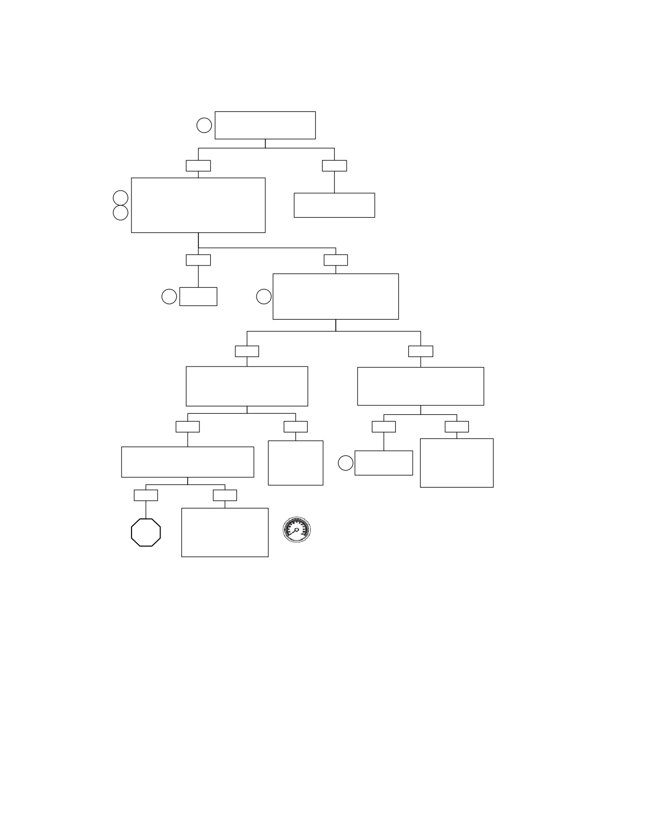
Battery Voltage: DTC P0562, P0563 (Part 1 of 2)
Perform charging system tests.
1
Charging system OK?
YES
NO
Connect Breakout Box. Measure voltage
on Breakout Box between terminal “72” (+)
2
and terminal “73” (-) with engine
Repair charging system.
running at 2000 RPM or higher for 10
See Section 1.
3
seconds or longer.
Is voltage above 11.0 volts?
YES
NO
With ignition ON, measure voltage drop
between battery positive (+) terminal
System
1
4
and Breakout Box terminal “72” (-).
OK.
Is voltage drop greater
than 0.5 volt?
YES
NO
With ignition OFF, measure resistance
Check for voltage drop between battery
between Breakout Box terminal “72”
negative (-) terminal and terminal “73” (-)
and connector [22B] terminal “4". Is
on Breakout Box.
resistance greater than 1 ohm?
Is voltage drop greater than 0.5 volt?
NO
YES
YES
NO
Replace (W/BK)
Problem is intermittent.
Measure resistance between ignition fuse
wire between
See 4.8
Locate and repair
terminal and connector [22B] terminal “3”.
connectors
5
WIGGLE TEST.
bad connection.
Is resistance greater than 1 ohm?
[22B] and [78B]
Locate and repair
or terminals.
bad connection.
YES
NO
Inspect connector [22] for
Clear codes using speedometer self
corrosion or loose wires.
diagnostics. See 4.6 SPEEDOMETER
STOP
If above conditions are not
SELF DIAGNOSTICS. Confirm proper
present, replace Engine
operation with no check engine lamp.
Stop Switch.
Go to Battery
fc01047_en
Voltage: DTC
P0562, P0563
(Part 2 of 2).
4-128 2008 Touring Diagnostics: Engine Management
HOME
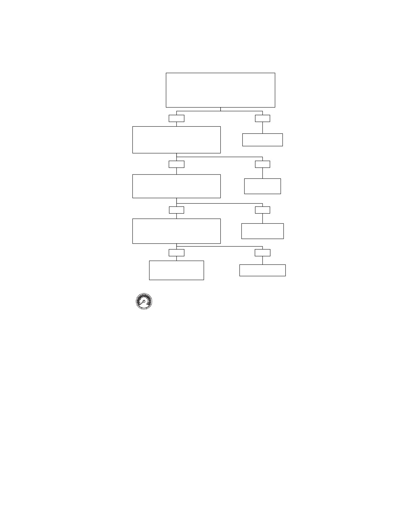
Battery Voltage: DTC P0562, P0563 (Part 2 of 2)
Continued from Battery Voltage: DTC P0562, P0563
(Part 1 of 2).
With Ignition Switch in IGNITION position, measure
voltage drop between battery positive (+) terminal and
terminal (GY) on 15 amp Ignition Fuse (-).
Is voltage drop greater than 0.5 volt?
YES
NO
With Ignition Switch in IGNITION position,
measure voltage drop between battery
Replace (GY) wire
positive (+) terminal and terminal (R/BK) at
or terminals.
15 amp Ignition Fuse.
Is voltage drop greater than 0.5 volt?
YES
NO
With Ignition Switch in IGNITION position,
measure voltage drop between battery
Replace Fuse or
positive (+) and both fuse terminals (-).
fuse terminals.
Is voltage drop greater than 0.5 volt?
YES
NO
With Ignition Switch in IGNITION position,
measure voltage drop between battery
Replace Ignition
positive (+) terminal and one fuse terminal
(-
Switch or terminals.
). Is voltage drop greater than 0.5 volt?
YES
NO
High resistance between
MAXIFUSE and Battery.
Replace MAXIFUSE.
Replace wire or terminals.
Clear codes using speedometer self diagnostics.
See 4.6 SPEEDOMETER SELF DIAGNOSTICS.
fc01048_en
Confirm proper operation with no check engine
lamp.
2008 Touring Diagnostics: Engine Management 4-129
HOME
DTC P0572
4.27
low, the rear brake switch may not receive sufficient
GENERAL
pressure to actuate the switch. Replenish brake fluid in
Brake Switch
the brake reservoir(s), as necessary.
There are two stop lamp switches. The front stop lamp switch
•
An intermittent may be caused by poor connection, rubbed
is a mechanical switch located on the right hand controls. The
through wire insulation or a wire broken inside the insula-
rear brake switch is a pressure switch located in the brake line
tion.
under the exhaust pipes.
Check for the following conditions:
On vehicles not equipped with Antilock Brake System (ABS),
•
Poor connection: Inspect component and harness con-
when the stop lamp switches are closed they supply power to
nectors for backed out terminals, improper mating, broken
the coil side of the brake relay. This energizes the brake relay
locks, improperly formed or damaged terminals, poor ter-
and supplies power to the stop lamp. The stop lamp switches
minal-to-wire connection and damaged harnesses.
also supply an input to the ECM.
•
Fluid leaks: Check the rear brake switch for fluid leaks
On vehicles equipped with ABS, when the stop lamp switches
around the seal of the switch. Refer to Service Manual to
are closed each switch supplies a separate input to the ABS
repair a fluid leak.
module. Power is also supplied through the ABS diode pack
to the ECM (as a brake input) and to the brake relay. The brake
Diagnostic Notes
relay energizes and supplies power to the stop lamps.
Each reference number below correlates to a circled number
During an ignition cycle, the ECM must receive a valid brake
on the flow chart(s).
switch input. Then during the same ignition cycle the vehicle
has to reach
31 MPH (50 km/h) in third gear or higher and
1. When checking the (O/W) wire, from the accessory fuse
return to a stop three times with out any brake switch signals
for a short to ground, remember to check the wires on the
in order to set DTC P0572.
other side of the switches for shorts to ground as well.
These circuits could cause a short to the accessory fuse
but ONLY when the switch is closed. The accessory fuse
Table 4-48. Code Description
circuit supplies power to the cigar lighter, horn, left and
DTC
DESCRIPTION
right turn signal switches, front and rear brake switches
and the cruise control switch.
P0572
Brake switch input error
DIAGNOSTICS
Diagnostic Tips
•
Check that the rear brake reservoir has the proper amount
of brake fluid, and there are no apparent leaks. If fluid is
4-130 2008 Touring Diagnostics: Engine Management
HOME
[39B]
em00104
[22A] [22B]
Right
Hand
(Black)
Controls
O/W
1
1
R/BE
2
2
3
3
O/W
6
6
Accessory
Right Directional
Switch
Stop Lamp Switch
Speedometer
[108B]
O/W
6
6
Accessory
Horn Switch
O/W
Left Directional
Switch
[24A] [24B]
(Gray)
Tachometer
Left
Electronic
Hand
Control
Controls
[78A] [78B]
O/W
1
1
Module
To
O/W
ACCY
fuse
Brake switch
25
25
R/BE
[1B]
5
[2B]
1
1
[1A]
5
[2A]
[33B]
30(3)
87(5)
Ignition
R/Y
O/V
R/GY
1
Switch
85(2)
2
Cruise
[33A]
BK
3
86
Brake
(1) Brake
Fuse
Relay
15 Amp
[4A]
[12B]
[7A]
[121B]
1 2
2
4
32
56
[121A]
1 2
ACC
Tour-pak
Rear
Connector
[12A]
Brake
Switch
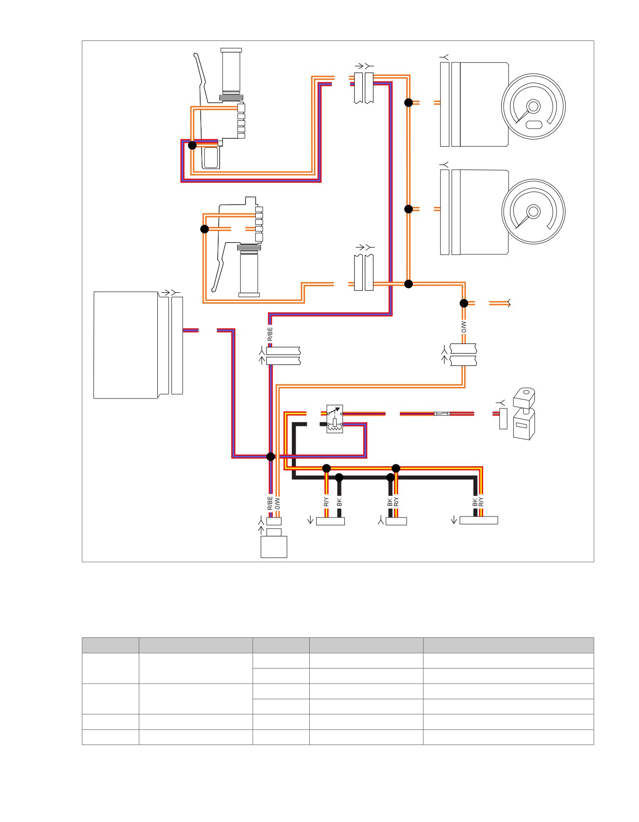
Figure 4-59. Brake Control Circuit Without ABS
Table 4-49. Wire Harness Connectors
NO.
DESCRIPTION
MODEL
TYPE
LOCATION
[1]
Main to interconnect har-
FLHT/C
16-place Molex (Black)
Inner fairing - right radio support bracket
ness
FL
TR
16-place Molex (Black)
Inner fairing - below radio (right side)
[2]
Main to interconnect har-
FLHT/C
12-place Molex (Gray)
Inner fairing - right faring support brace
ness
FL
TR
12-place Molex (Gray)
Inner fairing - below radio (right side)
[4]
Accessory connector
All
4-place Deutsch (Black)
Under seat - left side of chassis
[7]
Rear fender lights harness
All
8-place Multilock
Top of rear fender (under seat)
2008 Touring Diagnostics: Engine Management 4-131
HOME
Table 4-49. Wire Harness Connectors
NO.
DESCRIPTION
MODEL
TYPE
LOCATION
[12]
T
our-Pak lights (rear fascia
All
3-place Multilock
Inside Tour-Pak (inboard of upper frame
lamp on FLHX)
tube on FLHX)
[22]
Right handlebar switches
FLHT/C
12-place Molex (Black)
Inner fairing (fork stem nut lock plate)
FLTR
12-place Molex (Black)
Inside headlamp nacelle
[24]
Left handlebar switches
FLHT/C
12-place Molex (Gray)
Inner fairing (fork stem nut lock plate)
FLTR
12-place Molex (Gray)
Inside headlamp nacelle
[33]
Ignition switch
All
3-place Packard
Inner fairing - under radio
[39]
Speedometer
All
12-place Packard
Inner fairing - back of speedometer
[78]
Electronic Control Module
All
73-place Delphi
Under seat
(ECM)
[108]
T
achometer
FLHT/C
12-place Packard
Inner fairing (back of tachometer)
FLTR
12-place Packard
Under bezel (back of tachometer)
[121]
Rear brake switch
All
2-place Delphi
Mid chassis, lower right side (between
frame and exhaust pipe)
4-132 2008 Touring Diagnostics: Engine Management
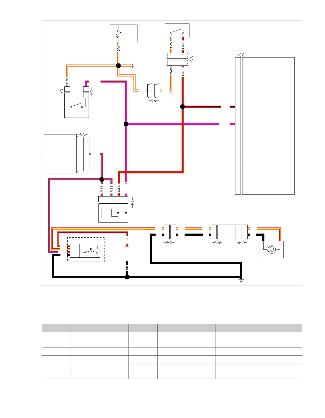
HOME
1C
Front Stop
em00157
[64-1]
ACCY
Lamp
Fuse
Switch
15 Amp
1D
[166B]
[166A]
ABS Module
1
2
[22A]
See appendix B
1
2
[22B]
main harness
page 1 of 3
PK/BN
[121-2B]
1
1
[121-1B]
O/W
5
5
O/W
[121-2A]
1
1
[121-1A]
Rear
[1B]
[1A]
Stop
R/BN
13
13
Front brake input
Pressure
Lamp
(Except FLHR)
Switch
Switch
Electronic
PK/BN
3
3
Rear brake input
Control
Module (ECM)
[78A] [78B]
Brake switch input
25
25
R/BE
4
3
2
1
[201B]
ABS
4
3
2
1
[201A]
Diode
Pack
Circuit Board
R/Y
6
6
R/Y
R/Y
4
4
3
3
R/Y
BK
5
5
BK
BK
6
6
4
4
BK
Brake Relay
O/V
3A
87
5
Tail/Stop
[7A] [7B]
[94B] [94A]
[93A] [93B]
R/Y
2B
30
3
See appendix B
Lamp
R/BE
2A
85
2
main harness
BK
3B
86
1
page 1 of 3
[64-2]
[GND 1A]
Figure 4-60. Brake Control Circuit With ABS
Table 4-50. Wire Harness Connectors
NO.
DESCRIPTION
MODEL
TYPE
LOCATION
[1]
Main to interconnect har-
FLHT/C
16-place Molex (Black)
Inner fairing - right radio support bracket
ness
FL
TR
16-place Molex (Black)
Inner fairing - below radio (right side)
[7]
Rear fender lights harness
All
8-place Multilock
Top of rear fender (under seat)
[22]
Right handlebar switches
FLHT/C
12-place Molex (Black)
Inner fairing (fork stem nut lock plate)
FL
TR
12-place Molex (Black)
Inside headlamp nacelle
[64]
Fuse block
All
Packard
Under left side cover
2008 Touring Diagnostics: Engine Management 4-133

HOME
Table 4-50. Wire Harness Connectors
NO.
DESCRIPTION
MODEL
TYPE
LOCATION
[78]
Electronic Control Module
All
73-place Delphi
Under seat
(ECM)
[93]
T
ail lamp
All
4-place Multilock
Circuit board under tail lamp assembly
[94]
Rear fender lights harness
All
6-place Multilock
Circuit board under tail lamp assembly
in circuit board
[121]
Rear brake light switch
All
Spade terminals
Bottom of rear frame downtube (right side)
[166]
ABS module
All
20-place Molex
Under right side cover
[201]
ABS diode
All
4-place Deutsch
Under left side cover (below fuse box)
4-134 2008 Touring Diagnostics: Engine Management
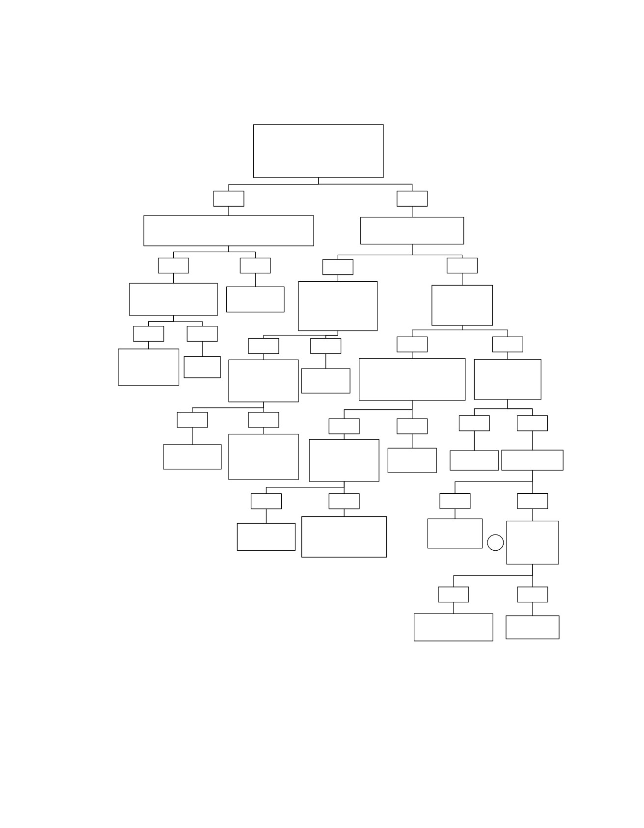
HOME
Brake Switch: DTC P0572
Turn on Ignition Switch with the Engine
Stop Switch in the RUN position. Apply
the rear brake and the front brake
independently of each other.
Does the Stop Lamp illuminate both when
the front or the rear brake is applied?
YES
NO
Disconnect connector [78]. Turn Ignition Switch on.
Does the Stop Lamp illuminate
Apply brakes. Test for voltage on (R/BE) terminal “25”.
when the front brake is applied?
Is voltage present?
YES
NO
YES
NO
Perform 4.8 WIGGLE TEST
Disconnect the rear stop
Repair open in
Does the Stop
to check for intermittents.
lamp switch. Test for
(R/BE) wire.
Lamp illuminate
Intermittents present ?
voltage on (O/W) wire
when the rear
connector [121-2].
brake is applied?
Is voltage present?
YES
NO
YES
NO
YES
NO
Repair connectors,
terminals or wires
Replace
Using a jumper lead
Disconnect the front stop lamp
Test for voltage at
found to have
ECM.
connect [121-1] to
Repair open in
switch. Test for voltage on (O/W)
Accy Fuse connector
intermittents.
connector [121-2].
(O/W) wire.
wire connector [22B] terminal “1”.
[64-1] terminal “1D”
Does the Stop Lamp
Is voltage present?
Is voltage present?
illuminate?
YES
NO
YES
NO
YES
NO
Repair open in (PK/
Using a jumper lead
Replace Rear
BN) wire. If equipped
connect [121-1] to
Stop Lamp
with ABS check the
Repair open in
Repair open in
Inspect Accy Fuse.
connector [121-2].
switch.
ABS Diode Pack for
(O/W) wire.
(O/W) wire.
Is fuse good?
Does the Stop Lamp
open as well.
illuminate?
YES
NO
YES
NO
Repair open in (R/BN)
Repair open in
Test for a short
Replace Front
wire. If equipped with ABS
(R/GY) wire
to ground.
Stop Lamp
check the ABS Diode Pack
terminal “1C”.
1
Refer to note.
switch.
for open as well.
Short to ground
present?
YES
NO
Repair short to ground
Replace Accy
and replace Accy Fuse.
Fuse.
fc01245_en
2008 Touring Diagnostics: Engine Management 4-135
HOME
DTC P0577
4.28
orange to green to indicate that the cruising speed is
GENERAL
locked in. See Figure 4-63.
The ECM controls and monitors the operation of the vehicle
4.
The ECM monitors both the engine RPM and the VSS
cruise control. The Cruise Control ON/OFF Switch allows the
output speed signal. The ECM signals the throttle control
control circuit to be enabled or disabled and, when enabled,
actuator to open or close the throttle to keep the speedo-
the lamp in the switch illuminates.
meter output speed signal constant. The engine RPM is
Actual engagement of the vehicle cruise control is provided by
monitored to detect engine overspeed, a condition which
the Cruise SET/RESUME Switch, located on the operator Right
automatically causes cruise disengagement.
Hand Controls. This switch is a 3 position momentary switch,
spring loaded to the center position.
5.
The ECM automatically disengages cruise mode whenever
the ECM receives one of the following inputs:
Switch-Right Position (SET/COAST)
a. Front or rear brake is applied.
•
When the switch is toggled to the right position and
b. Throttle is "rolled back" or closed, thereby actuating
released, the cruise control is engaged and SET to current
throttle roll-off (disengage) command.
vehicle speed.
•
If the switch is toggled right and held momentarily, then
c. Motorcycle clutch is disengaged (ECM senses too
the cruise control enters the COAST mode.
great an increase in RPM).
Switch-Left Position (RESUME/ACCELERATE)
d. Cruise ON/OFF Switch placed in the OFF position.
The switch is located on the fairing cap of FLHTCU
•
After brakes are applied or throttle is forced towards the
models, the instrument nacelle of FLTR models, and
stop, the clutch is disengaged, then the cruise control is
the left handelbar lower switch housing on FLHRC
disengaged. When the switch is toggled to the left position
models. The green Cruise Enabled/Engaged lamp in
then released, the cruise control is engaged and will
the tachometer face (speedometer on FLHRC models)
RESUME the previously SET speed/condition.
is extinguished to indicate that the system is deactiv-
•
If the switch is toggled left and held momentarily while the
ated. The orange lamp in the fairing cap switch of
cruise control is engaged, then the ACCELERATE is
FLTR models is also extinguished.
provided, increasing the vehicle RPM/SPEED. If the switch
e. Handlebar-mounted Engine Stop Switch placed in
is toggled left and held, it continues to increase the vehicle
the OFF position.
speed until the switch is released and allowed to return to
the neutral position.
f.
Handlebar-mounted Cruise SET/RESUME Switch is
pushed to SET and held in that position until vehicle
speed drops below 30 MPH (48 km/h) or pushed to
Table 4-51. Code Description
RES until vehicle speed exceeds 85 MPH (137 km/h).
DTC
DESCRIPTION
NOTE
P0577
Cruise Control Input Error
If the vehicle speed is above
30 MPH (48 km/h) when the
SYSTEM OPERATION
Cruise SET/RESUME Switch is released, then the cruise
system automatically re-engages.
To engage and disengage the cruise control system, proceed
as follows:
1. While riding in fourth, fifth, or sixth gear, turn the Cruise
ON/OFF Switch to the ON position. See Figure 4-61. The
switch is located on the fairing cap of FLHTCU models,
the instrument nacelle of FLTR models, and the left
handlebar lower switch housing on FLHRC models. The
Cruise Enabled/Engaged lamp in the tachometer face
(speedometer on FLHRC models) turns orange to indicate
that the system is activated. See Figure 4-63. An orange
lamp in the switch on both FLHTCU and FLTR models
also indicates this condition to the rider.
2. With the motorcycle traveling at the desired "cruise" speed,
30-85 MPH (48-137 km/h), momentarily push the Cruise
SET/RESUME switch to SET. See Figure 4-62.
3. The ECM "reads" the Vehicle Speed Sensor (VSS) to
establish the desired vehicle speed. The ECM then mod-
ulates the throttle control actuator to maintain vehicle
speed. The Cruise Enabled/Engaged lamp in the tacho-
meter face (speedometer on FLHRC models) turns from
4-136 2008 Touring Diagnostics: Engine Management
HOME
ed02072
ed01551
1
2
1
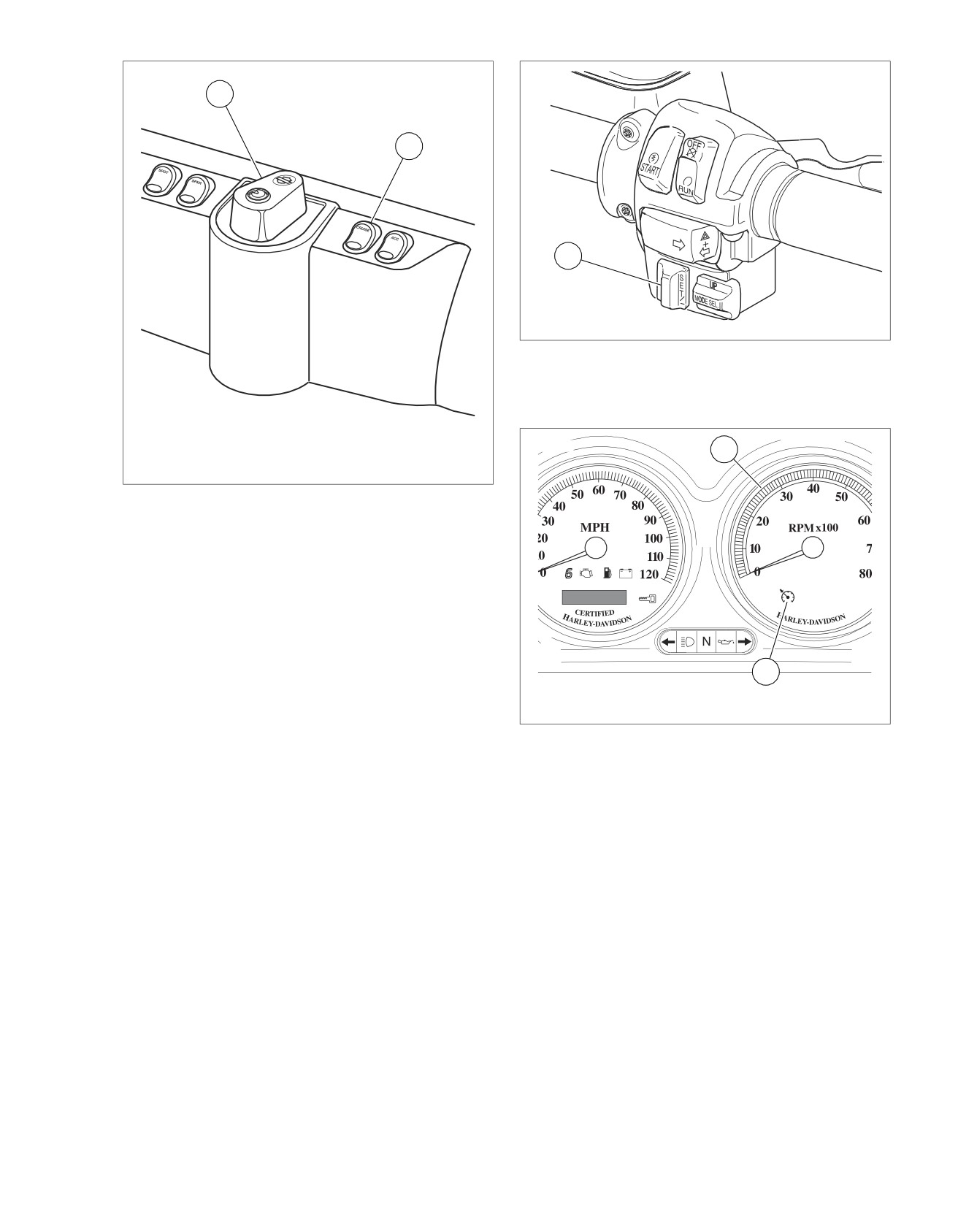
1. Set/Resume Switch
Figure 4-62. Right Handlebar Switch Assembly (FLTR,
FLHTCU)
ed02071
1
1. Ignition/Light Key Switch
2. Cruise ON/OFF Switch
Figure 4-61. Fairing Cap (FLHTCU)
2
1. Tachometer
2. Cruise Enabled/Engaged Lamp
Figure 4-63. Instrument Panel (FLHTCU)
2008 Touring Diagnostics: Engine Management 4-137
HOME
ed01545
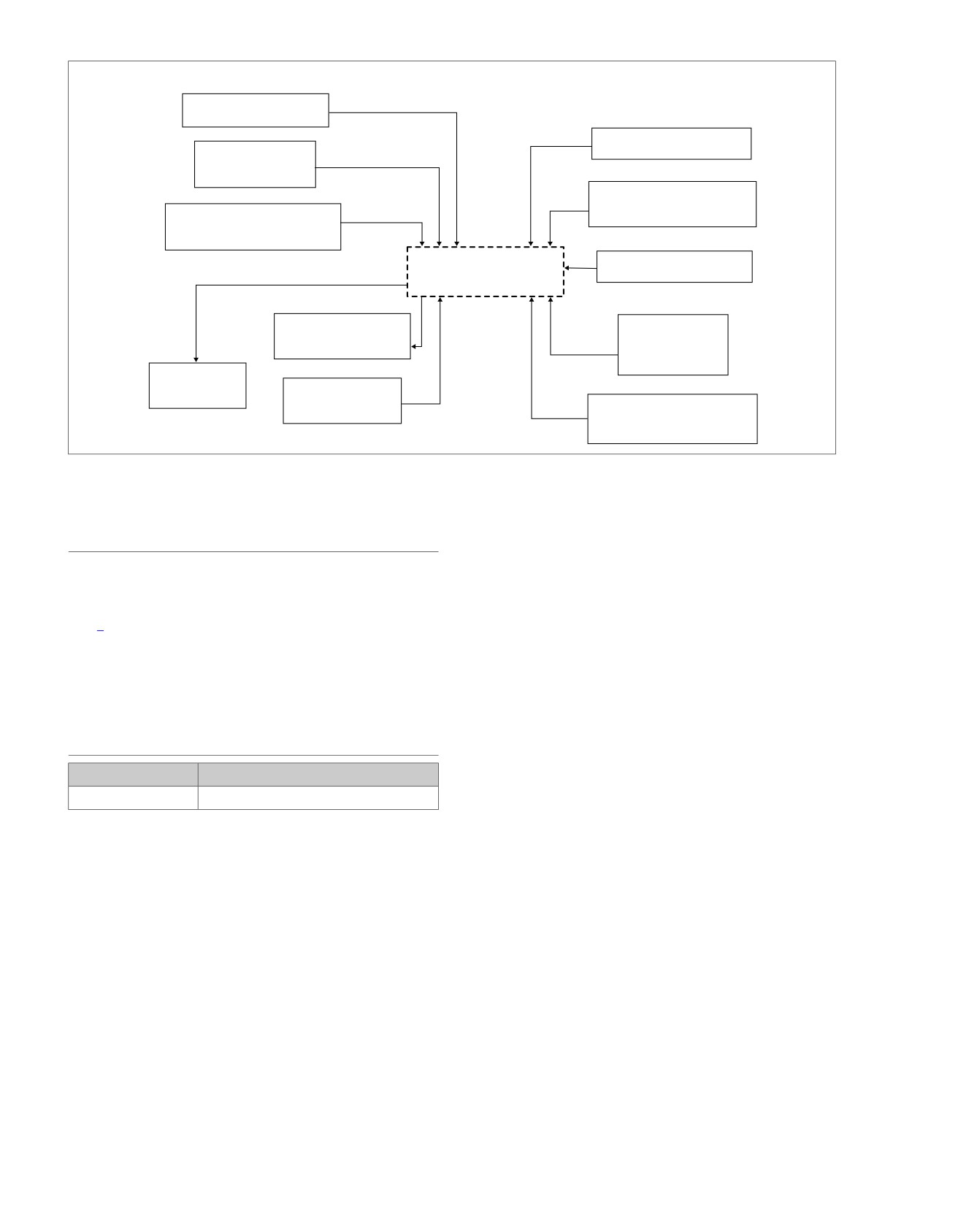
ENGAGE SEQUENCE
DISENGAGE SEQUENCE
CRUISE SWITCH ON
FRONT/REAR BRAKE
SET/RESUME
SWITCH TO SET
THROTTLE ROLL-OFF
READS VSS
OUTPUT SPEED SIGNAL
ECM
CRUISE SWITCH OFF
CRUISE ENGAGED
HANDLEBAR
LAMP
ENGINE STOP
SWITCH OFF
THROTTLE
ACTUATION
ENGINE RPM
MONITORED
CLUTCH DISENGAGE
(ENGINE RPM)
Figure 4-64. Cruise System Diagram
1.
Connect BREAKOUT BOX (Part No. HD-48637) to the
TROUBLESHOOTING
ECM and ECM harness. See 4.7 BREAKOUT BOX: EFI.
The ECM provides on-board diagnostics to help isolate any
2.
Use HARNESS CONNECTOR TEST KIT (Part No. HD-
problems that occur with the cruise system.
41404-B), purple pin probes, socket probes and patch
If the cruise is inoperative or fails to set, begin troubleshooting
cords.
with Table 4-53. If the cruise seems to disengage or drop out
for no apparent reason, see Cruise Control Inoperative: DTC
3.
Replace defective mechanical components in accordance
P0577 (Part 1 of 2).
with the Service Manual. Follow the flow chart steps
provided until component replacement directs you to the
In the diagnostic mode, the Cruise Enabled/Engaged lamp is
Service Manual.
employed as a test indicator. The lamp is in the tachometer
face (speedometer on FLHRC models). See Figure 4-63.
4.
If the cruise engaged lamp (green) does not illuminate at
all, check for one or more of the following conditions:
DIAGNOSTICS
a. SET/RESUME switch faulty or not wired correctly.
PART NUMBER
TOOL NAME
b. Broken or pinched wire to SET switch.
HD-41404-B
HARNESS CONNECTOR TEST KIT
c. Cruise engaged lamp burned out or miswired.
Diagnostic Tips
d. Faulty cruise main switch and associated wiring.
•
An intermittent may be caused by poor connection, rubbed
e. Brake light on constantly.
through wire insulation or a wire broken inside the insula-
tion.
5.
Repeat Step 1. If the cruise engaged lamp still does not
illuminate, see Cruise Control: Initial Diagnostics. Repair
•
Poor connection: Inspect component and harness con-
any problems then recheck by repeating Step 1.
nectors for backed out terminals, improper mating, broken
locks, improperly formed or damaged terminals, poor ter-
6.
Use HARNESS CONNECTOR TEST KIT (Part No. HD-
minal-to-wire connection and damaged harnesses.
41404-B), gray female probe and patch cord.
Diagnostic Notes
Each reference number below correlates to a circled number
on the flow chart(s).
4-138 2008 Touring Diagnostics: Engine Management
HOME
Right
[39B]
[39A]
em00105
Hand
[22A]
[22B]
Control
W/BK
4
4
O/W
6
6
Accessory
W/BE
11
11
Cruise
BE/BK
12
12
Speedometer
Set/
Resume
Switch
[108B] [108A]
Cruise
R/GN
Switch
O/V
O/W
6
6
Accessory
[15A] [15B]
Fairing
A
A
Dash Panel
Harness
B
B
Switches
C
C
12
5
4
R/GN
12
12
Cruise enable
Tachometer
BK
D
D
[105A]
[105B]
12
5
4
Electronic Control
[78A]
[78B]
Module
BK
Cruise set/coast
22
22
BE/BK
System relay enable
27
27
GN/O
[1B]
5
6
14 15 16
Main Harness
5
6
14 15 16
[1A]
Cruise resume/accelerate
34
34
W/BE
Cruise enable
35
35
R/GN
[33B]
Ignition
15 Amp
Switch
O/W
R/GY
1
[33A]
2
Accessory Fuse
3
12V power
52
52
V/GN
System
Relay
30
(3)
87(5)
BE/GY
V/GN
86(1)
85(2)
W/BK
GN/O
12V battery
71
71
BE/GY
12V run/stop switch
72
72
W/BK
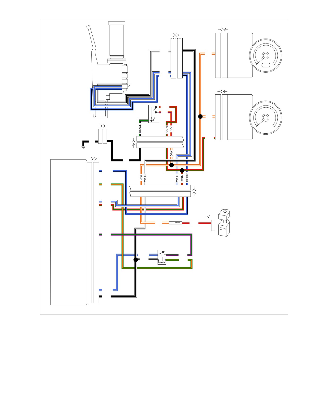
Figure 4-65. Cruise Control Circuit Diagram
2008 Touring Diagnostics: Engine Management 4-139
HOME
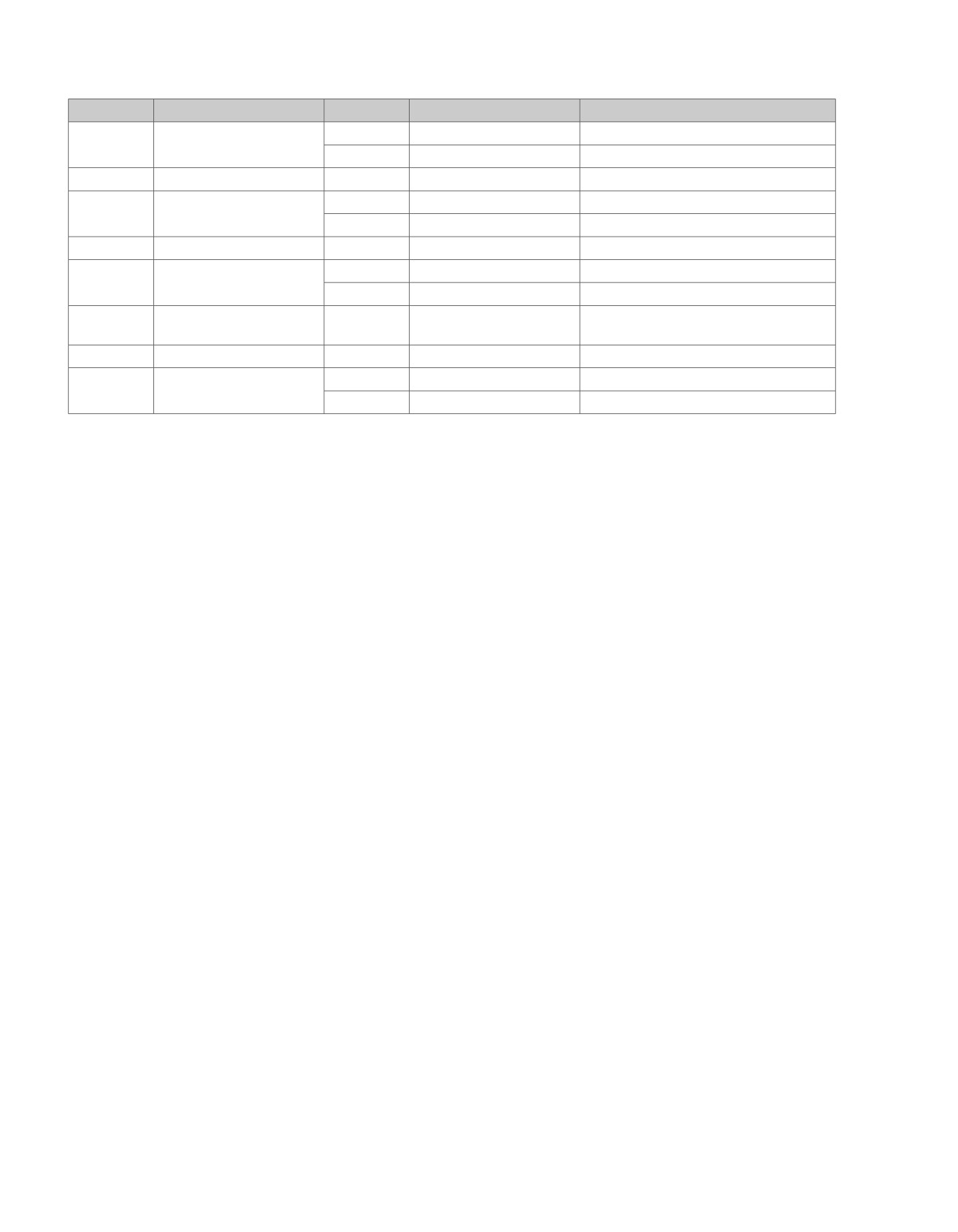
Table 4-52. Wire Harness Connectors
NO.
DESCRIPTION
MODEL
TYPE
LOCATION
[1]
Main to interconnect har-
FLHT/C
16-place Molex (Black)
Inner fairing - right radio support bracket
ness
FLTR
16-place Molex (Black)
Inner fairing - below radio (right side)
[15]
Faring harness
All
4-place Molex
Inner fairing - below radio
[22]
Right handlebar switches
FLHT/C
12-place Molex (Black)
Inner fairing (fork stem nut lock plate)
FLTR
12-place Molex (Black)
Inside headlamp nacelle
[33]
Ignition switch
All
3-place Packard
Inner fairing - under radio
[39]
Speedometer
FLHT/C
12-place Packard
Inner fairing (back of speedometer)
FLTR
12-place Packard
Under bezel (back of speedometer)
[78]
Electronic Control Module
All
73-place Delphi
Under seat
(ECM)
[105]
Dash panel switches
All
12-place Delphi
Inner fairing - beneath dash panel
[108]
T
achometer
FLHT/C
12-place Packard
Inner fairing (back of tachometer)
FLTR
12-place Packard
Under bezel (back of tachometer)
4-140 2008 Touring Diagnostics: Engine Management
HOME
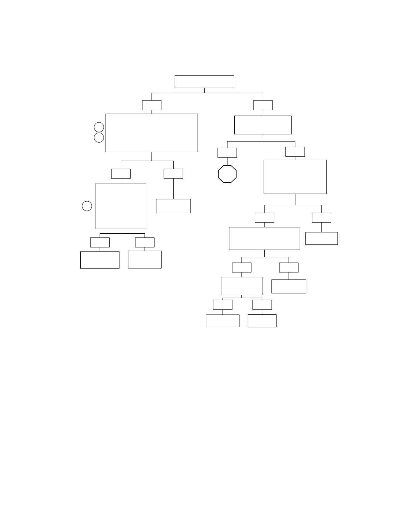
Cruise Control Inoperative: DTC P0577 (Part 1 of 2)
Check for DTCs.
Was DTC P0577 displayed?
YES
NO
Connect Breakout Box to ECM connector [78].
Turn on Cruise Switch.
With Ignition Switch in the IGNITION position
Does cruise control indicator
1
and the Engine Stop Switch in the RUN position
on gauges illuminate?
turn Cruise Switch on. Check for voltage
2
between terminal “22” (BE/BK) and ground and
between terminal “34” (W/BE) and ground.
Is voltage present?
YES
NO
Disconnect connector [105].
With Ignition Switch in the
YES
NO
STOP
IGNITION position test for
voltage between terminal “4”
connector [105B] and ground.
Disconnect connector
Go to Cruise Control
Is voltage present?
[22]. Test for voltage on
Inoperative: DTC P0577
connector [78] between
(Part 2 of 2).
terminal “22” and ground
Refer to
2
and between terminal
Diagnostic Tips.
“34” and ground.
Is voltage present on
YES
NO
either terminal?
With Cruise Switch on check for
continuity between terminal “4” and
Repair open in
YES
NO
terminal “5” of connector [105A].
(O/W) wire.
Is continuity present?
Repair short to
Replace Cruise
voltage in
Set/Resume
appropriate circuit.
Switch.
YES
NO
Inspect for open in
Replace Cruise
(R/GN) wire.
Switch.
Is open present?
YES
NO
Repair open in
Replace
(R/GN) wire.
Tachometer.
fc01249_en
2008 Touring Diagnostics: Engine Management 4-141
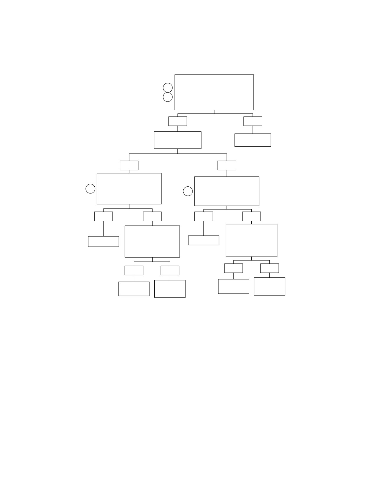
HOME
Cruise Control Inoperative: DTC P0577 (Part 2 of 2)
Continued from Cruise Control
Inoperative DTC P0577 (Part 1 of 2).
1
Connect Breakout Box to ECM connector
2
[78]. With the Cruise Switch on test for
voltage on terminal “35” of Breakout Box.
Is voltage present?
YES
NO
Does the Cruise Control
Locate and repair
SET work but not the
open in (R/GN).
RESUME?
YES
NO
With the Cruise Switch on and the
Cruise Set/Resume Switch
With the Cruise Switch on and the
pressed to RESUME test for
Cruise Set/Resume Switch
2
voltage on terminal “34” of
2
pressed to SET test for voltage on
connector [78].
terminal “22” of connector ]78].
Is voltage present?
Is voltage present?
YES
NO
YES
NO
Disconnect connector [22].
Disconnect connector [22].
With Cruise Set/Resume
With Cruise Set/Resume
Switch pressed to RESUME
Switch pressed to SET test
Replace ECM.
Replace ECM.
test for continuity between
for continuity between
terminals “4” and “11”.
terminals “4” and “12”.
Is continuity present?
Is continuity present?
YES
NO
YES
NO
Replace Cruise
Replace Cruise
Repair open in
Repair open in
Set/Resume
Set/Resume
(BE/BK) wire.
(W/BE) wire.
Switch.
Switch.
fc01250_en
4-142 2008 Touring Diagnostics: Engine Management

HOME
format. Follow the numbered steps to test the system. Compare
CRUISE INOPERATIVE DIAGNOSTICS
the system behavior CORRECT FUNCTION to INCORRECT
Refer to Table 4-53. All diagnostics steps are listed in table
FUNCTION columns and advance to the next step listed.
Table 4-53. Cruise Inoperative Diagnostics
NO.
ACTION
CORRECT FUNCTION
INCORRECT FUNCTION
1
Enter the diagnostic mode: with fairing
The cruise engaged lamp will illuminate
If the cruise engaged lamp remains
cap cruise ON/OFF switch at ON, and
and will remain on as long as the cruise
illuminated after the switch is released
the handlebar-mounted cruise set to
SET/RESUME Switch is held in the
then either the switch or related wiring
SET/RESUME Switch held at SET, turn
SET position.
is shorted.
the Ignition Switch to IGNITION.
Continue with Step 2.
2
Push the handlebar-mounted cruise
The cruise engaged lamp will illuminate
If the cruise engaged lamp does not
SET/RESUME switch to RES(UME)
and remain on as long as the
illuminate at all, check for one or more
and hold in this position.
SET/RESUME Switch is held in the
of the following conditions:
RES(UME) position.
•
RES(UME) switch not wired cor-
Continue with Step 3.
rectly.
•
Broken or pinched wire to
RES(UME) switch or cruise control
module.
Continue with Cruise Control: Resume
Switch.
3
Next, turn the throttle grip tightly closed
The cruise engaged lamp will illuminate
If the cruise engaged lamp does not
to check the throttle roll-off command.
when the grip is closed (roll-off posi-
illuminate at all, go to 4.44 DTC P2135,
tion), and then be extinguished when
P2138.
the throttle grip returns to its free posi-
tion.
Continue with Step 4.
4
Apply the front brake lever.
The cruise engaged lamp will illuminate
If the cruise engaged lamp does not
and remain on until the brake lever is
illuminate at all, check for one or more
released.
of the following conditions:
Continue with Step 5.
•
Front brake switch not wired cor-
rectly.
•
Broken or pinched wire to front
brake switch or cruise control
module.
•
Front brake switch not working
properly.
See Cruise Control: Brake Lights
Always On or 4.27 DTC P0572.
5
Apply the rear brake pedal.
The cruise engaged lamp will illuminate
If the cruise engaged lamp does not
and remain on until the brake pedal is
illuminate at all, check for one or more
released.
of the following conditions:
Continue to Step 6.
•
Rear brake switch not wired cor-
rectly.
•
Broken or pinched wire to front
brake switch or cruise control
module.
•
Rear brake switch not working
properly.
See Cruise Control: Brake Lights
Always On or 4.27 DTC P0572.
6
To restart or repeat the diagnostic
sequence, return to Step 1.
2008 Touring Diagnostics: Engine Management 4-143
HOME
CRUISE DISENGAGE CAUSES
DISENGAGE Request
OFF Request
•
Cruise control is under speed, under target speed
•
Cruise control is over speed, over target speed
•
Ignition is off
•
Cruise control is under speed, under target speed for
•
Cruise ON/OFF switch is off (open)
excessive time
•
Excessive battery voltage
•
Cruise control is over speed, over target speed for
•
Throttle position fault P0120, P0220
excessive time
•
Vehicle speed sensor fault P0501, P0502
•
Brake is applied for debounce time
•
Cruise switch failure P0577
•
Twist grip roll-off
•
TP sensor correlation error P2135
•
Both the SET/COAST and the RESUME/ACCELERATE
switches are pressed at the same time
•
Flash checksum error P0605
•
Engine run time minimum not met
•
Brake switch fault P0572
•
Clutch lever is pulled in (declutched)
•
TBW limited performance mode P1510
•
Excessive vehicle acceleration rate
•
Vehicle speed exceeds maximum cruise speed limit
•
Vehicle speed below minimum cruise speed limit
•
Engine speed exceeds maximum engine speed limit
•
Engine speed below minimum engine speed limit
•
Excessive engine speed acceleration
•
Vehicle speed governing active
•
Transmission is in too low of a gear or in Neutral
4-144 2008 Touring Diagnostics: Engine Management

HOME
DTC P0603,
P0605
4.29
GENERAL
DIAGNOSTICS
ECM Failure
These codes are set under two conditions.
Refer to Table 4-54. The DTCs listed indicate a failure which
•
If DTC P0603 or P0605 occur during normal operation,
requires replacement of the ECM. See the Service Manual for
replace ECM. Reprogram and learn password.
replacement information.
•
If DTC P0603 or P0605 occur during or after reprogram-
NOTE
ming, perform the following:
After replacing ECM perform password learning procedure and
DTC P0603
clear codes.
1. Clear DTCs.
Table 4-54. Code Description
2. Power down the vehicle. Wait 10 seconds.
DTC
DESCRIPTION
3. Turn Ignition Switch to IGNITION.
P0603
ECM EEPROM error
4. Replace ECM if codes reappear.
P0605
ECM flash error
DTC P0605
1. Clear DTCs.
2. Power down the vehicle.
3. Attempt to reprogram ECM using correct calibration.
4. Restart vehicle. If code reappears, replace ECM.
2008 Touring Diagnostics: Engine Management 4-145