Harley Davidson 2011 Touring Models. Service Manual - page 17
 

  Главная      Harley Davidson     Harley Davidson 2011 Touring Models. Service Manual


Search            copyright infringement  


Content      ..     15      16      17      18     ..


Harley Davidson 2011 Touring Models. Service Manual - page 17


N

2

1

5

6

3

4

sm02867

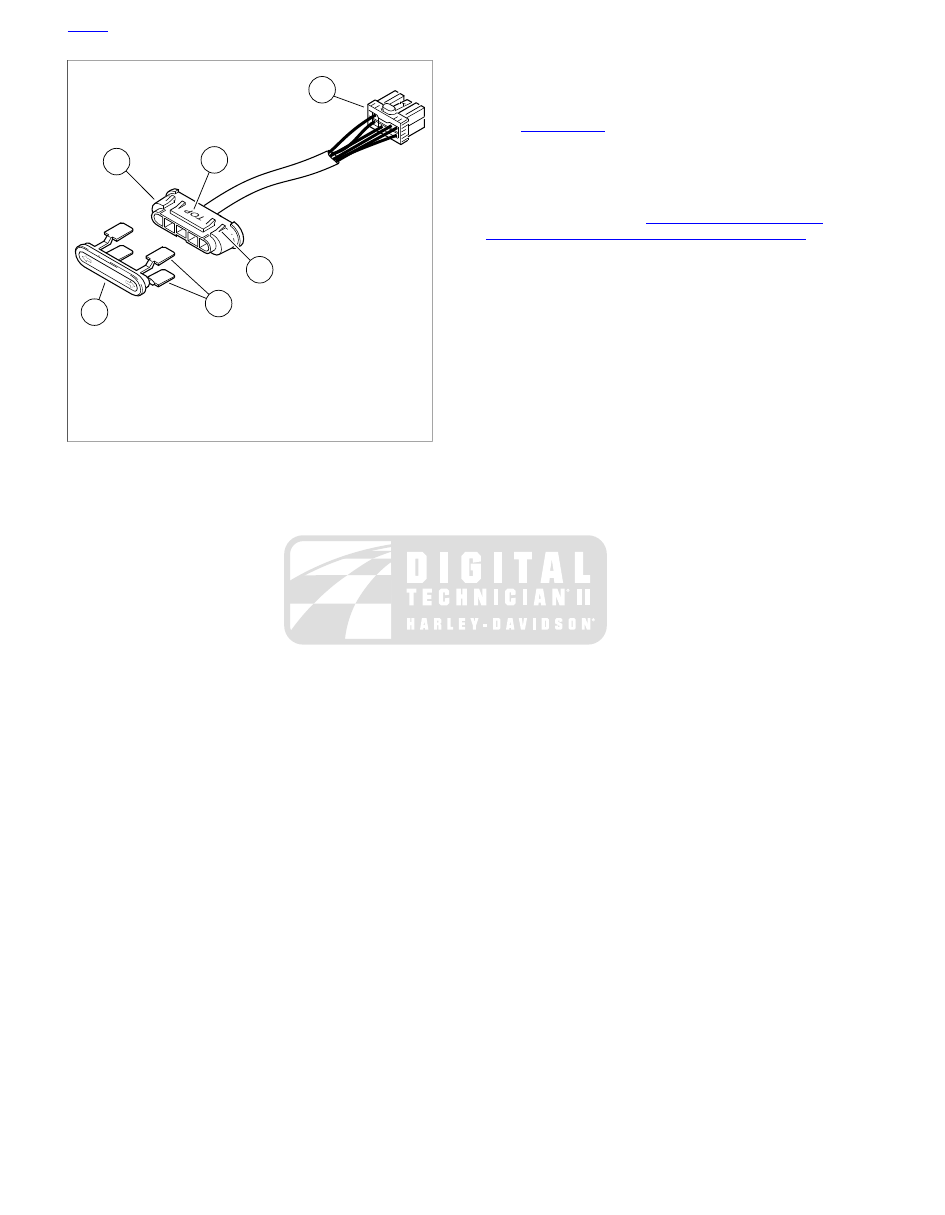
1. Indicator lamp connector [21]
2. Indicator lamp assembly
3. Lens
4. Paddles
5. Index tabs
6. Orientation stamp

Figure 2-126. Indicator Lamp Assembly

21. Slide slots of auxiliary lamp bracket onto upper and lower

fork bracket screws. Tighten four screws to 15-20 ft-lbs
(20-27 Nm) in a crosswise pattern.

22. See

Figure 2-122

. Mate left and right front turn

signal/auxiliary lamp connectors (1,2). Install on T-studs
at top of left and right fairing support braces (outboard
side). Verify that conduit is routed inboard using relief in
upper outboard corner of chrome skirt.

23. Install outer fairing. See

2.34 UPPER FAIRING AND

WINDSHIELD: FORK MOUNTED FAIRING MODELS

.

HOME

2-102 2011 Touring Service: Chassis

2.37

AIR DEFLECTORS

AIR DEFLECTORS

Removal

1.

See

Figure 2-127

. Remove four screws to release air

deflector at side of inner fairing.

2.

Repeat step to remove air deflector on opposite side of
motorcycle.

Installation

1.

Install four screws to fasten air deflector at side of inner
fairing. Alternately tighten screws to 25-30

in-lbs

(2.8-3.4

Nm).

2.

Repeat step to install air deflector on opposite side of
motorcycle.

sm04885

Figure 2-127. Air Deflector (Adjustable)

MID-FRAME AIR DEFLECTORS

Removal

1.

See

Figure 2-128

. Release spark plug wire from retainer

(3) (left deflector only).

2.

Remove bolts (5) and washers (4).

3.

Remove deflector (6) from frame.

Installation

1.

See

Figure 2-128

. Verify clip nut (2) is installed in frame

hole.

2.

Install left air deflector (6) with washers (4) and bolts (5).
Tighten bolts to 25-35

in-lbs

(2.8-4.0 Nm).

3.

Secure spark plug wire in retainer (3).

1

7

4

5

6

5

4

3

2

sm05959

1. Right air deflector
2. Clip nut (2)
3. Rear spark plug wire retainer
4. Washer (4)
5. Bolt (4)
6. Left air deflector
7. Clinch nut (2)

Figure 2-128. Air Deflectors

HOME

2011 Touring Service: Chassis 2-103

2.38

UPPER FAIRING AND WINDSHIELD: FRAME
MOUNTED FAIRING MODELS

WINDSHIELD

Removal

1.

Remove five screws (with plastic flat washers) at base of
windshield.

2.

Remove windshield from outer fairing.

NOTE

The rubber trim at the bottom of the windshield is secured with
adhesive and is not intended to be removed. A new lower trim
is included with the replacement windshield. Follow the
instructions included with the replacement windshield to attach
the new lower trim.

3.

See

Figure 2-129

Carefully remove wellnuts (with rubber

flat washers) from holes in outer fairing.

NOTE

Exercise caution to avoid pushing wellnuts into fairing during
removal. Inspect wellnuts and rubber flat washers for cuts,
tears or signs of deterioration. Replace as necessary.

sm02871

Figure 2-129. Remove Wellnuts from Outer Fairing

Installation

1.

Preinstall

hardware on windshield as follows:

a.

Slide plastic flat washers onto screws.

b.

Slide screws through slots in windshield.

c.

Slide rubber flat washers onto wellnuts.

d.

Start wellnuts onto screws.

2.

See

Figure 2-130

. Push wellnuts into holes in outer fairing.

3.

Starting with center screw, alternately tighten five screws
to 6-13

in-lbs

(0.7-1.5 Nm).

1

3

2

5

4

sm02872

1. Screw
2. Plastic flat washer
3. Windshield
4. Wellnut
5. Rubber flat washer

Figure 2-130. Install Windshield

OUTER FAIRING

Removal

NOTE

Windshield may be left in place during outer fairing removal.

1.

Place protective material on top of front fender to protect
paint.

2.

See

Figure 2-131

. Remove screws (1).

3.

Loosen

screws (2).

4.

Remove screws (3).

5.

See

Figure 2-132

. Remove acorn nuts (with flat washers)

and remove front turn signal lamp assemblies. Allow to
hang from wires.

HOME

2-104 2011 Touring Service: Chassis

0

20

30

70

80

40

50

60

10

RPM x100

0

10

30

20

50

40

110

120

60 70

80

90

100

MPH

H

A

RL

EY

-DAV

I DSON MOTOR

CO

M

PA

N

Y

CERTIFIED

HARLEY-DAVID SON

H

A

RL

EY

-DAV

I DSON MOTOR

CO

M

PA

N

Y

1

3

2

2

1

3

sm02873

3.

1.

Long screw

Short screw

2. Short screw

Figure 2-131. Fairing Screw Torque Sequence

6.

Raise outer fairing slightly and then rest on protective
fender pad and separate headlamp harness connector.

7.

To avoid possible wire damage, separate front turn signal
lamp connectors and remove lamps.

Installation

1.

Place protective material on top of front fender to protect
paint.

NOTE

The front turn signal lamp assemblies are not interchangeable.
Note that the letters R(ight) or L(eft) are stamped on the inboard
side of the turn signal lamp bracket to help verify proper
assembly.

2.

Mate front turn signal lamp connectors. Capture harnesses
in adhesive clips on inner fairing. Allow front turn signal
lamp assemblies to hang until outer fairing installation is
complete.

3.

Verify that trim strips are installed inboard of hooks on
radio bracket.

4.

Rest outer fairing on front fender pad and mate headlamp
harness connector.

NOTE

If windshield is attached during outer fairing installation, exer-
cise caution to avoid scratching or damaging inner fairing with
windshield screws and wellnuts.

5.

Place outer fairing against inner fairing with two slots in
outer fairing engaged in hooks on radio bracket. Verify full
engagement between outer and inner fairings.

6.

Verify that inner fairing alignment tabs are properly
engaged and positioned outboard of those on the outer
fairing.

NOTE

Install the first screw on the side that does not have the best
fit.

7.

Loosely install screws (1).

8.

Loosely install screws (2).

9.

Loosely install screws (3).

HOME

2011 Touring Service: Chassis 2-105

10. Tighten screws in sequence shown in

Figure 2-131

.

Tighten screws (1, 2) to 6-12

in-lbs

(0.7-1.4 Nm). Tighten

screws (3) to 10-15

in-lbs

(1.1-1.7 Nm).

11. Install turn signal lamps and secure with acorn nuts and

flat washers. Tighten acorn nuts to 60-84

in-lbs

(6.8-9.5

Nm).

sm02874

Figure 2-132. Remove Acorn Nuts to Release Turn Signal

Lamp and Bracket

HOME

2-106 2011 Touring Service: Chassis

2.39

INSTRUMENT BEZEL: FRAME MOUNTED
FAIRING MODELS

BEZEL

Removal

1.

See

Figure 2-133

Remove screws (1) on each side of

bezel.

2.

Push forward to release tab at rear of bezel from slot in
front of ignition switch. Raise free side of bezel until front
tabs are disengaged.

0

20

30

70

80

40

50

60

10

RPM x100

0

10

30

20

50

40

110

120

60 70

80

90

100

MPH

H

A

RL

EY

-DAV

I DSON MOTOR

CO

M

PA

N

Y

CERTIFIED

H

A

RL

EY

-DAV

I DSON MOTOR

CO

M

PA

N

Y

1

3

2

sm02876

1. Screw (2)
2. Bezel
3. Instrument nacelle

Figure 2-133. Remove Bezel Screws

HOME

2011 Touring Service: Chassis 2-107

2

5

3

1

4

6

sm02877

4.

1.

Speaker switch [105C/D]

Indicator lights [21]

2.

5.

Speedometer gauge [39]

Tachometer gauge [108]

6.

3.

Clutch cable

Instrument nacelle switches [105A/B]

Figure 2-134. Frame Mounted Fairing Models: Instrument Nacelle (Bezel Removed)

3.

See

Figure 2-134

. Raise bezel slightly and disconnect

instruments and indicator lights from interconnect harness
as follows:

a.

Speedometer connector (2).

b.

Tachometer connector (5).

c.

Indicator lights connector (1).

4.

Remove bezel from motorcycle.

Installation

1.

See

Figure 2-134

Connect instruments and indicator lights

to interconnect harness as follows:

a.

Speedometer connector (2).

b.

Tachometer connector (5).

c.

Indicator lights connector (1).

2.

Verify that left and right sides of instrument nacelle are
properly mated.

3.

Insert tab at rear of bezel into slot of instrument nacelle.
Hold left and right sides of nacelle together and place
bezel over instrument nacelle flange. When properly
mated, tabs at front of instrument nacelle engage lip in
slot at front of bezel.

NOTE

If tabs do not properly engage slot at front of bezel, remove
decorative adhesive strip by gently prying up outer edges using
a flat bladed screwdriver and carefully raise tabs so that they
engage lip in slot. If damaged, install new decorative adhesive
strip.

4.

See

Figure 2-133

Install screws (1) on each side of bezel.

Alternately tighten screws to 25-35

in-lbs

(2.8-4.0 Nm).

HOME

2-108 2011 Touring Service: Chassis

2.40

INSTRUMENT NACELLE: FRAME MOUNTED
FAIRING MODELS

INSTRUMENT NACELLE

Removal

1.

Remove key switch knob, spring, nut, collar, spacer and
switch position plate. See

7.17 IGNITION/LIGHT KEY

SWITCH AND FORK LOCK

.

2.

Remove bezel. See

2.39 INSTRUMENT BEZEL: FRAME

MOUNTED FAIRING MODELS

.

3.

See

Figure 2-135

Disconnect speaker switch connector

(1) from instrument nacelle switch harness.

4.

Remove clutch cable clip from hole on left side of instru-
ment nacelle.

5.

See

Figure 2-136

Remove two screws (with flat washers)

to release left side of instrument nacelle from upper and
lower fork brackets.

6.

Remove rubber boot from odometer reset switch and pull
odometer reset switch from hole while removing left side
instrument nacelle from motorcycle, .

7.

See

Figure 2-135

. Disconnect instrument nacelle switch

connector (2) from interconnect harness.

8.

See

Figure 2-136

. Remove two screws (with flat washers)

to release right side of instrument nacelle from upper and
lower fork brackets.

1

2

sm04889

1. Speaker switch [105C/D]
2. Instrument nacelle switches [105A/B]

Figure 2-135. Instrument Nacelle Connectors

HOME

2011 Touring Service: Chassis 2-109

2

1

4

3

5

6

sm03585

4.

1.

Right side nacelle

Left side nacelle

2.

5.

Clutch cable clip hole

Speaker switch connector [105C]

6.

3.

Instrument nacelle switch connector [105B]

Speaker switch connector [105D]

Figure 2-136. Instrument Nacelle Halves

Installation

1.

Install right side of instrument nacelle on motorcycle.

2.

See

Figure 2-135

Connect instrument nacelle switch

connector (2) to interconnect harness.

3.

While carefully placing left side of instrument nacelle on
motorcycle, slide odometer reset switch through hole and
install rubber boot.

4.

Connect speaker switch connector (1) to instrument
nacelle switch harness.

5.

Verify that left and right sides of nacelle are properly mated
and that pins are fully engaged in holes on right nacelle.

6.

Install screws (with flat washers) to fasten left and right
side instrument nacelle to upper and lower fork brackets.
Tighten screws to 15-20 ft-lbs (20.3-27.1 Nm).

7.

Capture clutch cable in cable clip. Insert cable clip into
hole in left side of instrument nacelle.

8.

Install bezel. See

2.39 INSTRUMENT BEZEL: FRAME

MOUNTED FAIRING MODELS

.

9.

Assemble ignition switch. See

7.17 IGNITION/LIGHT KEY

SWITCH AND FORK LOCK

.

HOME

2-110 2011 Touring Service: Chassis

2.41

INNER FAIRING: FRAME MOUNTED FAIRING
MODELS

REMOVAL

TOOL NAME

PART NUMBER

IGNITION SWITCH CONNECTOR
REMOVER

HD-45961

1.

Place protective material on top of front fender to protect
paint.

2.

Remove outer fairing. See

2.38 UPPER FAIRING AND

WINDSHIELD: FRAME MOUNTED FAIRING MODELS

.

3.

Cut two cable straps to free wire bundles from interconnect
harness.

4.

See

Figure 2-137

. Separate interconnect harness con-

nector (1), interconnect harness connector (2), and inter-
connect harness connector (3).

5.

Remove antenna cable connector (9) from radio.

6.

Separate twist grip sensor jumper harness connector (10)
from main harness.

10

2

7

6

1

9

5

4

3

8

sm02878

6.

1.

Left turn signal [31L]

Main to interconnect harness [1]

2.

7.

Main to interconnect harness [2]

Right turn signal [31R]

8.

3.

Headlamp [38]

Main to interconnect harness [15]

4.

9.

Right handlebar switches [22]

Radio antenna [51]

10.

5.

Twist grip sensor jumper harness [204]

Left handlebar switches [24]

Figure 2-137. Inner Fairing Connectors (FLTR)

7.

See

Figure 2-137

Separate left handlebar switch con-

nector (5) and right handlebar switch connector (4).

8.

Remove interconnect harness ground socket terminal from
spade contact at front of upper fork bracket (left side).

HOME

2011 Touring Service: Chassis 2-111

9.

Draw the main harness, radio antenna cable, twist grip
sensor jumper harness, and handlebar switch harness as
far forward as possible. Rest the connectors of the longer
harnesses on the front fender.

10. Remove

left

side

of

instrument

nacelle.

See

2.40 INSTRUMENT NACELLE: FRAME MOUNTED
FAIRING MODELS

.

11. Separate ambient temperature sensor connector [107], 3-

place Multilock, from sensor and feed harness through
opening on left side of fairing bracket.

12. See

Figure 2-138

. Draw branches of interconnect harness

through tunnel of fairing bracket to front of inner fairing.

1

2

sm02879

1. Main harness
2. Interconnect harness

Figure 2-138. Wrap Main Harness in Shop Towels

13. Disconnect ignition switch connector [33], 3-place Packard,

at front of ignition switch housing. Proceed as follows:

a.

Gently insert end of IGNITION SWITCH CON-
NECTOR REMOVER (Part No. HD-45961) into slot
in ignition switch housing until it stops.

b.

Pull both the main harness and the tool at the same
time to release connector housing from ignition switch
housing.

14. Draw branch of main harness with ignition switch con-

nector through tunnel of fairing bracket to front of inner
fairing.

15. Separate any branches of the interconnect harness that

may be intermingled with the main harness. Allow the
interconnect harness to hang along the left side of the
front fender.

16. See

Figure 2-138

. Capturing all connectors, tightly wrap

clean shop towels around the main harness, radio antenna
cable, twist grip sensor jumper harness, and handlebar
switch harness, and secure with masking tape.

17. See

Figure 2-139

. Remove four locknuts (9) to release

radio bracket and inner fairing from fairing bracket.

18. Lift inner fairing (with attached radio bracket and intercon-

nect harness) from fairing bracket studs and move to
bench area.

Disassembly

1.

Remove right side instrument nacelle. See

2.40 INSTRU-

MENT NACELLE: FRAME MOUNTED FAIRING MODELS

.

2.

Remove shop towels and masking tape from around the
harness bundle and separate.

3.

Pull main harness out through opening on right side of
fairing bracket and hang over top of engine guard.

4.

ABS equipped:

Draw front wheel speed sensor connector

[167], 2-place Amp (Tyco), out through opening on left
side of fairing bracket and disconnect from main harness.

5.

Draw main to interconnect harness connector [2] out left
side of fairing bracket and hang over top of engine guard.

6.

Pull handlebar switch conduit and twist grip sensor jumper
harness conduit out through opening at top of fairing
bracket.

7.

Remove locknuts (3) and bolts (2) to release fairing bracket
from steering head.

HOME

2-112 2011 Touring Service: Chassis

1

4

7

6

8

9

11

10

5

2

3

sm03563

7.

1.

Slot

Fairing bracket

2.

8.

Bolt (2)

Radio bracket

9.

3.

Locknut (4)

Locknut (2)

4.

10.

Studs

Outer fairing hooks

11.

5.

Trim strip

Inner fairing

6. Opening

Figure 2-139. Inner Fairing Assembly

INSTALLATION

Outer Fairing

1.

See

Figure 2-139

Install fairing bracket and secure with

bolts (2) from right side. Install locknuts (3) and tighten to
20-30 ft-lbs (27.1-40.7 Nm).

2.

See

Figure 2-140

Route handlebar switch harness and

twist grip sensor jumper harness through opening at top
of fairing bracket.

3.

ABS equipped:

Mate front wheel speed sensor connector

[167] to main harness.

4.

Route main harness that terminates with interconnect
harness [2] and wheel speed sensor [167] connectors
through the opening on the left side of fairing bracket.

5.

Route main harness that terminates with the radio antenna
cable [51], twist grip sensor jumper harness [204], ignition
switch [33], and main to interconnect harness connectors,
[1] and [15], through the opening on the right side of fairing
bracket.

6.

See

Figure 2-138

. Draw wire harnesses out tunnel of

fairing bracket and pull as far forward as possible. Tightly
wrap clean shop towels around the main harness, radio
antenna cable, twist grip sensor jumper harness, and
handlebar switch harness, and secure with masking tape.

7.

Install right side instrument nacelle. See

2.40 INSTRU-

MENT NACELLE: FRAME MOUNTED FAIRING MODELS

.

Inner Fairing

1.

Place protective material on top of front fender to protect
paint. Rest inner fairing (with attached radio bracket and
interconnect harness) on front fender.

2.

See

Figure 2-139

. Place inner fairing over four fairing

bracket studs while feeding end of harness bundle through
opening (6). Verify that sides of inner fairing are positioned
outboard of both fairing supports (on engine guards).

3.

Install four locknuts (9). Tighten locknuts to 96-144

in-lbs

(10.9-16.3 Nm).

4.

See

Figure 2-138

Draw the harness bundle as far forward

as possible, resting the end of the bundle on the front
fender.

5.

Feed the branch of the interconnect harness terminating
in the ambient temperature sensor connector from front
of the inner fairing into the tunnel and then out through
the opening on the left side of the fairing bracket. Mate
the connector to the ambient temperature sensor.

6.

Feed the branch of interconnect harness terminating in
odometer reset switch and speedometer, tachometer,
indicator lights and instrument nacelle switch connectors
from the front of the inner fairing through the tunnel of the
fairing bracket and then out through opening at top of
fairing bracket to instrument nacelle.

7.

Connect instrument nacelle switch connector [105A/B] to
interconnect harness.

HOME

2011 Touring Service: Chassis 2-113

8.

Remove shop towels and masking tape from the harness
bundle. Separate the harnesses from each other.

9.

Feed the branch of main harness terminating in ignition
switch connector from the front of the inner fairing through
the tunnel of the fairing bracket and then out through
opening at top of fairing bracket to instrument nacelle.

10. Mate ignition switch connector [33].

11. Connect interconnect harness ground terminal to the

spade contact at the front of the upper fork bracket (left
side).

12. See

Figure 2-137

Connect handlebar switches to intercon-

nect harness. Proceed as follows:

a.

Left handlebar switch connector (5).

b.

Right handlebar switch connector (4).

13. Connect twist grip sensor jumper harness connector (10)

to main harness.

14. Connect radio antenna cable connector (9).

15. Connect main harness to interconnect harness as follows:

a.

Main to interconnect harness connector (1) (black).

b.

Main to interconnect harness connector (2) (gray).

c.

Main to interconnect harness connector (3) (black).

16. Orient connectors. Install two

new

cable straps outboard

of radio bracket hooks to secure wire bundles to intercon-
nect harness. Cut any excess cable strap material.

NOTE

To avoid chafing wires of interconnect harness, verify that trim
strips are installed inboard of hooks on radio bracket.

17. Install outer fairing. See

2.38 UPPER FAIRING AND

WINDSHIELD: FRAME MOUNTED FAIRING MODELS

.

18. Install left side of instrument nacelle. See

2.40 INSTRU-

MENT NACELLE: FRAME MOUNTED FAIRING MODELS

.

19. Install bezel. See

2.39 INSTRUMENT BEZEL: FRAME

MOUNTED FAIRING MODELS

.

3

1

4

2

sm02880

1. Ignition switch
2. Twist grip sensor jumper harness
3. Left and right handlebar switches
4. Main harness

Figure 2-140. Route Main Harness and Conduit Thru Fairing

Bracket

HOME

2-114 2011 Touring Service: Chassis

2.42

GLOVE BOX DOOR AND HINGE: FRAME
MOUNTED FAIRING MODELS

GLOVE BOX DOOR AND HINGE

Removal

1.

Remove the outer fairing. See

2.38 UPPER FAIRING AND

WINDSHIELD: FRAME MOUNTED FAIRING MODELS

.

2.

See

Figure 2-141

Remove screw cover (2).

3.

Remove locknuts (5) and washers from screws (1).

NOTE

Hold glove box door closed as hinge screws are completely
removed to prevent it from unexpectedly falling.

4.

Remove screws (1) and door (3).

5.

If hinge replacement is necessary, remove plastic barrels
(6) to release hinge from door.

2

1

6

5

4

3

sm06511

1. Screw (2)
2. Screw cover
3. Door
4. Bumper (2)
5. Locknut (2)
6. Barrel (2)

Figure 2-141. Glove Box Door

Installation

1.

Place spring inside hinge inserting spring pin into closest
hole. With coil and one spring pin positioned inside hinge,
second spring pin is outside.

2.

Place hinge into position capturing free end of external
spring pin between ribs molded into glove box door.

3.

See

Figure 2-141

. Install plastic barrels (6). Slot in barrel

prevents interference with spring pin. Push barrels in until
tight.

NOTE

If removed, install new glove box door bumpers (4) in inner
fairing and pull anchor through hole.

4.

Place glove box door into position and secure with screws
(1), washers and locknuts (5).

5.

Snap screw cover (2) into place.

6.

Install the outer fairing. See

2.38 UPPER FAIRING AND

WINDSHIELD: FRAME MOUNTED FAIRING MODELS

.

HOME

2011 Touring Service: Chassis 2-115

2.43

WINDSHIELD: ROAD KING MODELS

WINDSHIELD

Removal

1.

See

Figure 2-142

Raise the wireform latch springs on

both sides of the windshield.

2.

Gently pull on the top of the windshield until the upper
notches on the windshield brackets are free of the upper
grommets.

3.

Carefully raise the windshield until the lower notches are
free of the lower grommets.

4.

Remove windshield from motorcycle.

2

6

5

4

3

1

sm03564

4.

1.

Upper grommet

Wireform latch spring

2.

5.

Windshield

Auxiliary lamp bracket

6.

3.

Clutch cable

Headlamp nacelle

Figure 2-142. Windshield (FLHR/C)

Installation

NOTE

To avoid scratching headlamp nacelle or auxiliary lamp bracket,
be sure that all four notches on the windshield brackets are
firmly seated on a rubber grommet.

1.

Carefully insert the windshield brackets between the
headlamp nacelle and the auxiliary lamp bracket. Lower
the windshield into position until the lower notches on the
windshield brackets are seated on the lower grommets.

2.

See

Figure 2-142

Gently push the top of the windshield

toward the rear until the upper notches fully engage the
upper grommets.

3.

Push down on the wireform latch springs, so that they
overhang the rubber grommets. If some adjustment is

necessary, loosen the retaining screws and rotate the latch
springs into the proper position.

WINDSHIELD WINDOW

TOOL NAME

PART NUMBER

ROBINAIR HEAT GUN

HD-25070

Removal

1.

Remove windshield. See

2.43 WINDSHIELD: ROAD KING

MODELS

.

2.

Place windshield front side up on clean padded surface.

3.

See

Figure 2-143

Remove acorn nuts and screws from

each vertical brace to release mounting bracket.

4.

Remove three remaining screws from horizontal brace.

HOME

2-116 2011 Touring Service: Chassis

2.48

REAR FRAME

REAR FRAME

Removal

When lifting a motorcycle using a jack, be sure jack con-
tacts both lower frame tubes where down tubes and lower
frame tubes converge. Never lift by jacking on cross-
members, oil pan or other housings. Failure to comply can
cause serious damage resulting in the need to perform
major repair work. (00586c)

1.

Lift the motorcycle with suitable lifting device.

2.

Remove the seat.

3.

See

Figure 2-157

Remove the top caddy and move caddy

aside. See

7.8 ELECTRICAL CADDIES

.

4.

Remove the battery. See

1.23 BATTERY MAINTENANCE

.

5.

FLHTC/U:

Remove the Tour-Pak. See

2.28 TOUR-PAK

.

6.

Cut cable straps securing harnesses to each side of rear
frame and luggage rack and move harnesses aside. Take
note of cable strap locations for reassembly.

7.

Remove rear fender. See

2.46 REAR FENDER

.

8.

Remove saddlebag supports. See

2.27 SADDLEBAG

SERVICE, Saddlebag Guard/Support Rail

.

9.

Remove shock absorbers. See

2.20 REAR SHOCK

ABSORBERS

.

10. Remove luggage rack if equipped. See

2.28 TOUR-PAK,

Luggage Rack/Tour-Pak Support

.

11. See

Figure 2-157

Remove two upper battery tray

fasteners (2).

12. Remove fastener that secures left-side electrical caddy to

rear frame.

13. See

Figure 2-158

Remove six fasteners (2) and washers

(3) securing the rear frame (1).

14. Remove rear frame.

1

2

sm05869

1. Top caddy fasteners
2. Rear battery tray fasteners

Figure 2-157. Upper Caddy Fasteners

1

3

2

sm05867

1. Rear frame
2. Fasteners (6)
3. Hardened washer (6)

Figure 2-158. Subframe

HOME

2-126 2011 Touring Service: Chassis


Content      ..     15      16      17      18     ..