Harley Davidson 2011 Touring Models. Service Manual - page 16
 

  Главная      Harley Davidson     Harley Davidson 2011 Touring Models. Service Manual


Search            copyright infringement  


Content      ..     14      15      16      17     ..


Harley Davidson 2011 Touring Models. Service Manual - page 16


7.

Install hinge pin with the tool bit recess on the inboard side
of the hinge.

8.

Apply a small dab of Loctite High Strength Threadlocker
262 (red) to threads of screw.

9.

Install screw into hinge pin and tighten to 20-25

in-lbs

(2.3-2.8 Nm).

10. Repeat previous steps to install second hinge pin.

11. Install tether. See

2.29 TOUR-PAK SERVICE, Tether

.

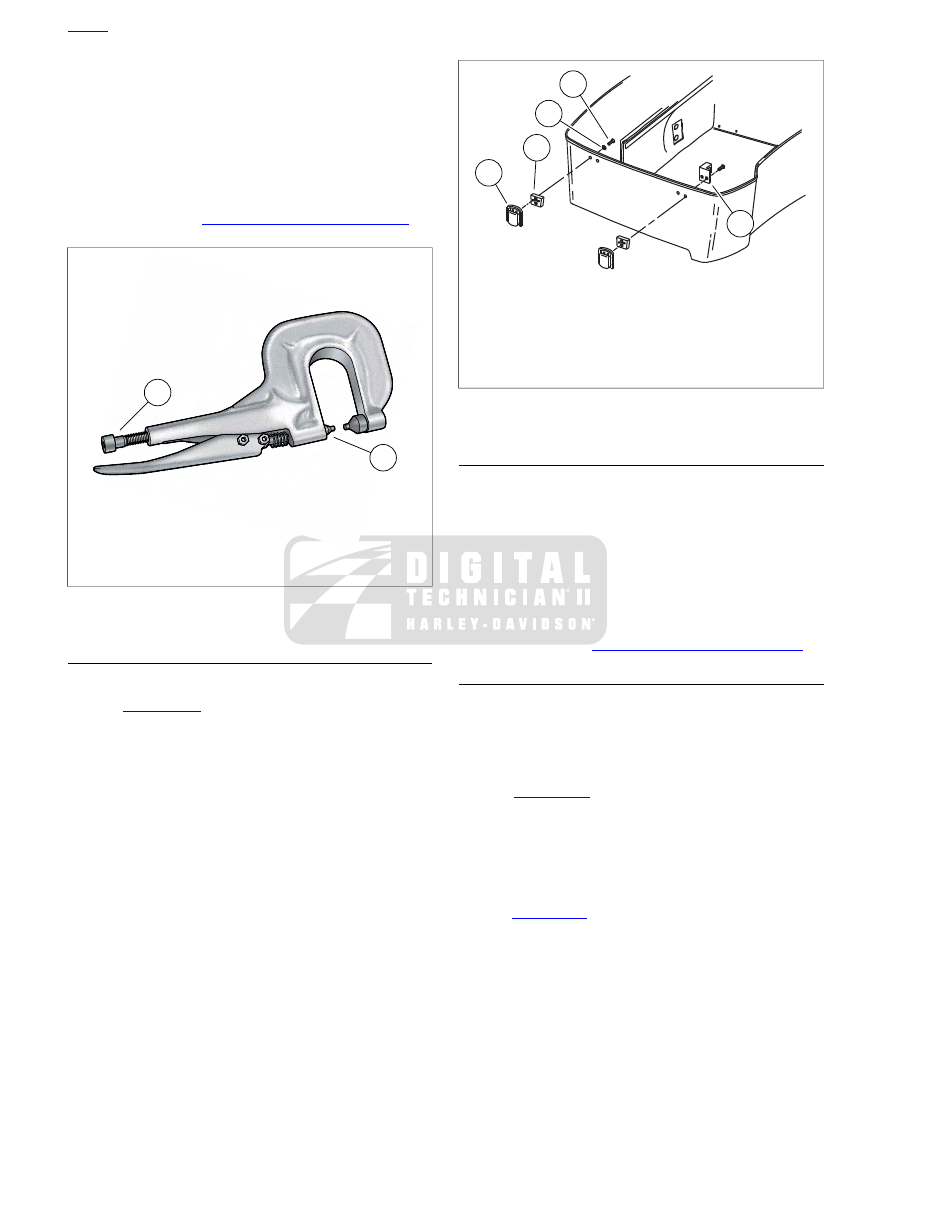
2

1

sm03552

1. Adjuster thumbscrew
2. Drive head

Figure 2-107. Rivet Tool (HD-39787A)

LATCHES/LOCKSET CATCH

Removal

1.

See

Figure 2-108

. Remove screws (1) and washers (2)

(rear only).

2.

Remove latch (4), spacer (3) and catch (5) (front only).

Installation

1.

Insert two short screws (with flat washers) through rear
holes or long screws through catch (5) and front holes.

2.

Slide spacer (3) onto screws with open side toward Tour
Pak.

3.

Apply a dab of Loctite Medium Strength Threadlocker 243
(blue) to threads of screws and install latch (4).

4.

Tighten screws to 20-25

in-lbs

(2.3-2.8 Nm).

1

2

5

3

4

sm06495

1. Screw (2 each latch)
2. Washer, rear only (2)
3. Spacer
4. Latch
5. Catch, front only

Figure 2-108. Tour Pak Latches

CATCHES

Removal

1.

Drill out rivets from inside Tour-Pak lid.

2.

Remove catch and backplate.

Installation

1.

With the head of the

new

rivet on the outboard side of the

Tour-Pak, slide rivet through holes in catch, Tour-Pak lid
and backplate.

2.

Install rivets. See

2.29 TOUR-PAK SERVICE, Hinges

.

TETHER

Removal

NOTE

Exercise caution to keep lid from opening beyond the normal
travel.

1.

See

Figure 2-109

. Remove screw (2).

2.

Remove tether eyelet (3) and wave washer from threaded
boss.

3.

Remove opposite end of tether from second tether bracket.

Installation

1.

See

Figure 2-109

. With the concave side toward the tether

bracket, install wave washer (4) onto threaded boss and
install tether eyelet.

2.

Apply a dab of Loctite High Strength Threadlocker 262
(red) to threads of screw.

3.

Install screw (2) and tighten to 20-25

in-lbs

(2.3-2.8 Nm).

4.

Repeat steps to secure opposite end of tether.

HOME

2-86 2011 Touring Service: Chassis

1

5

2

4

3

6

sm03554

1. Tether bracket (lid)
2. Screw
3. Tether eyelet
4. Wave washer (not visible)
5. Black nylon rivet
6. Flange nut (2)

Figure 2-109. Tour-Pak Tether Bracket Assembly

TETHER BRACKETS

TOOL NAME

PART NUMBER

RIVET TOOL

HD-39787A

Removing Tether Bracket from Tour-Pak

1.

Remove tether. See

2.29 TOUR-PAK SERVICE, Tether

.

2.

Drill out rivets from inside Tour-Pak.

3.

Remove tether bracket and backplate.

Removing Tether Bracket from Tour-Pak Lid

1.

Remove tether. See

2.29 TOUR-PAK SERVICE, Tether

.

2.

See

Figure 2-109

. From inside Tour-Pak lid, gently tap pin

out of rivet. Remove rivet. Repeat step to remove second
nylon rivet.

3.

Remove two flange nuts from studs of passenger backrest
bracket and remove tether bracket.

Installing Tether Bracket on Tour-Pak Lid

1.

See

Figure 2-109

From inside Tour-Pak lid, install tether

bracket on studs of passenger backrest bracket and start
flange nuts.

2.

Insert nylon rivets. Push pin into head of rivet until flush.

3.

Tighten flange nuts to 40-60

in-lbs

(4.5-6.8 Nm).

4.

Install tether. See

2.29 TOUR-PAK SERVICE, Tether

.

Installing Tether Bracket on Tour-Pak

1.

Install

new

rivets through the backplate, Tour-Pak and

tether bracket.

2.

Compress rivets using RIVET TOOL (Part No. HD-
39787A). See

2.29 TOUR-PAK SERVICE, Hinges

.

3.

Install tether. See

2.29 TOUR-PAK SERVICE, Tether

.

LUGGAGE RACK

1.

See

Figure 2-110

Hold the luggage rack while removing

nuts (5) and washers (4, 3). Remove luggage rack.

2.

If necessary, remove mounting studs (1).

3.

If removed, install mounting studs to installed height (A)
of 0.630 ± 0.020 in (16.0 ± 0.51 mm).

4.

Verify the mounting pads (2) are in place on the mounting
studs of the luggage rack.

5.

Hold the luggage rack in place on the Tour-Pak cover and
apply a small bead of silicone sealant around the studs
where they pass through the inside of the cover.

6.

Install one nylon washer, one flat washer and nut on each
stud.

7.

Tighten in a criss-cross pattern to 60-84

in-lbs

(6.8-9.5

Nm).

5

4

3

2

1

A

sm06603

1. Stud (4)
2. Mounting pad (4)
3. Nylon washer (4)
4. Flat washer (4)
5. Nut (4)

Figure 2-110. Luggage Rack

HOME

2011 Touring Service: Chassis 2-87

2.30

TOUR-PAK LIGHTS

GENERAL

All domestic model Ultra Tour-Paks are equipped with side
marker lights. Ultra models also have rear wrap-around lights,
each of which contains a 2-filament lamp. One filament is a
supplemental brake light and the other a supplemental tail
lamp.

SIDE MARKER LIGHTS (IF EQUIPPED)

Removal

1.

Remove map pouch and molded liner from Tour-Pak.

2.

See

Figure 2-112

. Disconnect side marker lights connector

(4 or 5).

3.

Remove two screws and remove side marker lights.

Installation

1.

See

Figure 2-112

. Feed socket through hole in Tour-Pak

and place side marker lights into position.

2.

Install two screws and tighten to 20-25

in-lbs

(2.3-2.8

Nm).

3.

Connect side marker lights connector (4 or 5).

4.

Install molded liner and map pouch. Close Tour-Pak.

TOUR-PAK LIGHTS HARNESS

Removal

1.

See

Figure 2-111

. Remove right-rear fastener (1), external

tooth lockwasher (2) and flange nut (4) to release harness
ground ring terminal (3).

2.

See

Figure 2-112

. Remove tail lamp bulb socket from both

wrap-around lights.

3.

Disconnect two side marker lights connectors. Release
harness from adhesive clips.

4.

See

Figure 2-111

Remove five remaining flange nuts (4)

from bottom of Tour-Pak.

5.

Remove two left side attaching screws (5) and lock
washers.

6.

Loosen two right side attaching screws (6) several turns
but do not remove.

7.

Lift left side of metal plate enough to remove harness from
underneath it.

8.

Remove Tour-Pak lights harness.

7

5

6

3

4

2

1

sm05825

1. Right-rear fastener
2. External tooth washer
3. Ground ring terminal
4. Flange nut (6)
5. Left side attaching screws
6. Right side attaching screws
7. Ground ring terminal

Figure 2-111. Tour-Pak

Installation

1.

Place Tour-Pak lights harness at bottom of Tour-Pak as
shown in

Figure 2-112

.

NOTE

Tour-Pak lights harness is the only one routed under the metal
plate.

2.

Lift metal plate and route lights harness inboard of bosses
as shown, with connector (1) outboard of the metal plate.
Use masking tape as necessary to fix position.

3.

See

Figure 2-111

. Install two left side fasteners (5) with

lock washers. Verify radio antenna ground ring terminal
(7) is installed under left rear fastener.

4.

Tighten fasteners (5, 6) to 96-120

in-lbs

(10.8-13.6 Nm).

5.

Install hex head screw (1), external tooth lockwasher (2)
and harness ground ring terminal (3). Install flange nut
(4).

6.

Install five remaining flange nuts (4) on threaded studs of
metal plate. Tighten all flange nuts to 65-70

in-lbs

(7.3-

7.9 Nm).

7.

Connect two side marker lights connectors. Capture har-
ness in two adhesive clips at rear of Tour-Pak.

8.

Install tail lamp bulb socket in both wrap-around lights.

HOME

2-88 2011 Touring Service: Chassis

1

6

6

7

4

2

3

5

sm03556

1. Tour-pak lights harness [12]
2. Left wrap-around light
3. Right wrap-around light
4. Left side marker lights connector [12-3]
5. Right side marker lights connector [12-2]
6. Rib gap
7. Masking tape

Figure 2-112. Tour-Pak Lights Harness

WRAP-AROUND LIGHTS (IF EQUIPPED)

Bulb Replacement

1.

Remove map pouch and molded liner from Tour-Pak.

2.

Remove bulb socket from wrap-around light and replace
bulb.

3.

Install bulb socket in wrap-around light.

4.

Install molded liner and map pouch in Tour-Pak.

Removal

1.

Remove map pouch and molded liner from Tour-Pak.

2.

Remove both antenna masts from lamp housing.

3.

Remove bulb sockets from wrap-around light.

4.

If equipped, remove nut, tooth washer and ring terminal
from CB antenna stud. Remove stud and remove base
from housing.

5.

Disconnect radio antenna cable connector.

6.

Remove nut, ring terminal and large flat washer from radio
antenna connector.

HOME

2011 Touring Service: Chassis 2-89

1

2

3

4

sm03557

1. Tour-pak
2. Caulking
3. Bulb housing
4. Metal clip

Figure 2-113. Wrap-around Light Assembly

7.

Using the original nut and a 1/2 in.-20 UNF nut as a jam
nut, remove connector stud from radio antenna base.
Remove base from lamp housing.

8.

See

Figure 2-113

. Remove caulking from around light bar.

Remove four flange nuts and metal clips to free light bar
from Tour-Pak.

Installation

1.

See

Figure 2-113

. Install light bar and secure with metal

clips and flange nuts. Seal perimeter of light bar with RTV
silicone sealer (Part No. 99710-88).

2.

Install radio antenna base into lamp housing and tighten
stud securely. Remove nuts.

3.

Install large flat washer and ring terminal onto antenna
connector. Install nut and tighten securely.

4.

Connect radio antenna cable.

5.

If equipped, install CB antenna base into lamp housing.
Install stud and tighten with hex key.

6.

Install ring terminal, tooth washer and nut onto CB antenna
stud. Tighten nut securely.

7.

Install bulb socket of both left and right side wrap-around
lights.

8.

Install both antenna masts.

9.

Install molded liner and map pouch.

HOME

2-90 2011 Touring Service: Chassis

2.31

TOUR-PAK BACKREST

PASSENGER BACKREST

Removal

1.

See

Figure 2-114

. Remove two flange nuts and backplate

(1). Remove center backrest from Tour-Pak lid.

2.

Remove two flange nuts (2) to release left side backrest.

NOTE

Hold the Tour-Pak lid as flange nuts (3) are removed. Unex-
pected release of the tether bracket can allow the Tour-Pak lid
to swing fully open, resulting in damage.

3.

Remove two flange nuts (3) to release right side backrest.

4.

Carefully remove backrest from the Tour-Pak lid.

3

1

4

2

sm03558

1. Center flange nuts and backplate
2. Left side flange nuts
3. Right side flange nuts
4. Passenger backrest

Figure 2-114. Passenger Backrest

Installation

1.

See

Figure 2-114

Locate backrest in place on Tour-Pak

lid. Install plastic cushion plate and backplate on studs
and start flange nuts (1).

2.

Start flange nuts (2) on left side studs.

3.

Start flange nuts (3) on right side studs.

4.

Tighten flange nuts to 40-60

in-lbs

(4.5-6.8 Nm).

RUBBER ISOLATORS

Removal

1.

Remove passenger backrest. See

2.31 TOUR-PAK

BACKREST, Passenger Backrest

.

2.

Center isolator:

See

Figure 2-115

. Remove flange nut

with lockwasher to release cushion plate from rubber
isolator stud. Remove flange nut with lockwasher to
release other stud from backrest support bracket.

3.

Outside isolator:

See

Figure 2-116

Remove flange nut

with lockwasher to release "L" bracket from rubber isolator
stud. Rotate rubber isolator to remove other stud from
threaded hole in backrest.

Installation

1.

Center isolator:

See

Figure 2-115

. Insert stud of

new

rubber isolator into hole of backrest support bracket and
install lockwasher and flange nut. Tighten flange nut until
snug. Install cushion plate, lockwasher and flange nut on
other stud. Orient cushion plate so that it is parallel to
backrest and then finger tighten flange nut only.

2.

Outside isolator:

See

Figure 2-116

. Install stud of

new

rubber isolator into threaded hole in backrest until snug.
Install "L" bracket, lockwasher and flange nut on other
stud. Finger tighten flange nut only.

NOTE

Always hold rubber isolator on end to be installed. Do not grasp
middle of rubber isolator or opposite end as excessive twisting
can result in separation of molded parts or other damage.

3.

Install passenger backrest. See

2.31 TOUR-PAK BACK-

REST, Passenger Backrest

.

4.

Gently pull back cover material of backrest to expose
underside and final tighten flange nuts previously finger
tightened.

5.

Verify that each side of rubber isolator is not twisted or
under any torsional load. Loosen flange nuts and adjust
rubber isolator if necessary.

HOME

2011 Touring Service: Chassis 2-91

1

2

3

sm03559

1. Cushion plate
2. Rubber isolator
3. Backrest support bracket

Figure 2-115. Center Isolator

1

2

sm03561

1. "L" bracket
2. Rubber isolator

Figure 2-116. Outside Isolator

PASSENGER BACKREST FLAP

Removal

1.

Remove map pouch and molded liner from Tour-Pak.

2.

Remove two screws with flat washers.

3.

Remove backrest flap.

Installation

1.

Secure backrest flap with two screws (with flat washers)
and acorn nuts. Tighten to 21-24

in-lbs

(2.4-2.7 Nm).

2.

Install molded liner and map pouch in Tour-Pak.

HOME

2-92 2011 Touring Service: Chassis

2.32

TOUR-PAK SPEAKER BOX

SPEAKER BOX

Removal

1.

Remove map pouch and molded liner from Tour-Pak.

2.

Remove grommet and draw rear speaker/passenger
controls connector out of speaker box. Separate connector
halves.

3.

Remove three screws with flat washers to free speaker
box from Tour-Pak.

Installation

1.

See

Figure 2-117

Install three screws with flat washers

to secure speaker box to Tour-Pak. Tighten bolts to 25-35

in-lbs

(2.8-4.0 Nm).

2.

Install molded liner and map pouch in Tour-Pak.

3.

Mate rear speaker/passenger controls connector. Push
connector into speaker box and install grommet.

2

3

1

sm06641

1. Speaker box fasteners
2. Speakers
3. Power outlet (if equipped)

Figure 2-117. Speaker Boxes

HOME

2011 Touring Service: Chassis 2-93

2.33

LOWER FAIRING AND ENGINE GUARD

LOWER FAIRING

Removal

1.

See

Figure 2-118

Remove glove box door flap (6).

2.

Remove two flange nuts (8) from clip studs and remove
fairing cap (10). Do not twist or rotate fairing cap or
damage may result.

3.

Remove locknut (5) and screw (3) to free assembly. Dis-
card rubber washer (4).

9

10

11

1

8

15

14

7

6

13

12

11

18

19

3

4

5

2

16

17

sm03562

11.

1.

T20 TORX screw (5)

Lower fairing

2.

12.

Engine guard clamp

Glove box tray

13.

3.

Glove box door

T40 TORX screw

4.

14.

Rubber washer

Locknut

15.

5.

Flat washer

Locknut

6.

16.

Door flap

Compression spring

17.

7.

Serrated washer (1 black, 1 white)

Push-in snap (4)

8.

18.

Flange nut (2)

Pivot screw

19.

9.

Vent door

Clip stud (2)

10. Fairing cap

Figure 2-118. Lower Fairing Assembly

Disassembly

1.

See

Figure 2-118

. Remove three screws (11) to release

glove box door (13) and glove box tray (12).

2.

Remove two screws (11) to release glove box door from
glove box tray.

HOME

2-94 2011 Touring Service: Chassis

3.

Remove locknut (14), flat washer (15), compression spring
(rubber sleeve) (16), glove box tray and two serrated
washers (17).

4.

Remove pivot screw from vent door arm.

Assembly

1.

Slide pivot screw up through hole in vent door arm.

2.

With the teeth facing upward, install serrated washer.
Square shaped boss at bottom of serrated washer should
engage square recess in vent door arm.

NOTE

Use one black and one white serrated washer. Using two
washers of the same color may result in a chirping noise when
the lower fairings are adjusted.

3.

Slide second serrated washer over pivot screw so that
teeth engage those on first serrated washer.

4.

Engage square shaped boss at top of second serrated
washer with square hole on glove box tray.

5.

Install compression spring (rubber sleeve), flat washer
and locknut on pivot screw. Verify that pin at front of glove
box tray engages slot at top of vent door.

6.

Tighten locknut only until flat washer is snug (does not
rotate) and then tighten an additional 1-1/2 turns. Verify
proper vent door operation.

NOTE

For best results, the 0.50 in. (12.7 mm) compression spring
must be compressed to a height of 0.420 to 0.460 in. (10.7-
11.7 mm).

7.

Secure glove box tray to glove box door with two screws
(11). Tighten to 20-25

in-lbs

(2.3-2.8 Nm).

8.

Secure glove box tray to lower fairing with three screws.
Tighten to 20-25

in-lbs

(2.3-2.8 Nm).

9.

Install glove box door flap.

Installation

1.

Place lower fairing into position at front of engine guard.

2.

See

Figure 2-118

Install

new

rubber washer (4), clamp

(2) and locknut (5) to attach bottom of lower fairing to
engine guard. Do not tighten locknut.

3.

Verify that two clip studs (9) are fully installed on fairing
cap.

4.

Position fairing cap (10) against lower fairing and start two
flange nuts (8) on clip studs.

5.

Verify that lower fairing is square. Tighten flange nuts (8)
to 35-40

in-lbs

(4.0-4.5 Nm).

6.

Hold locknut (5) and tighten screw (3) to 90-100

in-lbs

(10.2-11.3 Nm).

SERRATED WASHER REPLACEMENT

Removal

1.

Remove glove box door flap.

2.

Remove locknut, flat washer and compression spring
(rubber sleeve) from pivot screw in vent door arm. Remove
pivot screw.

3.

Carefully extract serrated washers. Discard washers.

Installation

NOTE

Use one black and one white serrated washer. Using two
washers of the same color may result in a chirping noise when
the lower fairings are adjusted.

1.

With the teeth up, install

new

serrated washer at top of

vent door arm. Be sure that square shaped boss on
washer engages square recess in arm.

2.

With the teeth down, install

new

serrated washer at bottom

of glove box tray. Be sure that square shaped boss on
washer engages square hole in tray.

3.

Slide pivot screw up through hole in center of vent door
arm.

4.

Install compression spring (rubber sleeve), flat washer
and locknut on pivot screw.

5.

Tighten locknut only until flat washer is snug (does not
rotate) and then tighten an additional 1-1/2 turns. Verify
proper vent door operation.

NOTE

For best results, the 0.50 in. (12.7 mm) compression spring
must be compressed to a height of 0.420 to 0.460 in. (10.7-
11.7 mm).

ENGINE GUARD

Removal

1.

Remove lower fairings, if present. See

2.33 LOWER

FAIRING AND ENGINE GUARD, Lower Fairing

. Remove

lower fairing clamps from engine guard.

2.

See

Figure 2-119

Remove two screws (1) to release ends

of engine guard from frame weldments.

3.

Remove screw (2) and flat washer (3) and remove engine
guard.

Installation

1.

See

Figure 2-119

. Insert tab at top of engine guard into

slot at base of steering head. Start screw (2) with flat
washer (3).

2.

Secure lower ends of engine guard to frame weldments
with screws (1).

3.

Tighten all three screws to 15-20 ft-lbs (20.3-27.1 Nm).

4.

Install lower fairing clamps on each side of engine guard.
Install lower fairings, if present. See

2.33 LOWER FAIRING

AND ENGINE GUARD, Lower Fairing

.

HOME

2011 Touring Service: Chassis 2-95

1

2

3

sm06496

1. Screw (2)
2. Screws
3. Flat Washer

Figure 2-119. Engine Guard

HOME

2-96 2011 Touring Service: Chassis

2.34

UPPER FAIRING AND WINDSHIELD: FORK
MOUNTED FAIRING MODELS

OUTER FAIRING AND WINDSHIELD

Removal

1.

Remove the main fuse.

2.

See

Figure 2-120

. Loosen but do not remove three screws

(1) (with flat washers) securing the windshield.

3.

Raise and remove the windshield.

4.

Remove two screws (2).

5.

Remove two screws (3).

NOTE

On models without auxiliary lamps, be sure to hold the outer
fairing in position as the last screw is removed.

6.

Remove the three screws (1).

7.

Tilt the outer fairing forward and separate headlamp con-
nector [38].

8.

Lift the outer fairing off the motorcycle.

Installation

1.

Place the outer fairing on the motorcycle and mate head-
lamp connector [38] to the headlamp assembly.

2.

See

Figure 2-120

Start three screws (1) (with flat

washers).

3.

Start two screws (2).

4.

Start two screws (3).

5.

Tighten screws (2, 3) to 20-30

in-lbs

(2.3-3.4 Nm).

6.

Place the windshield into position between the inner and
outer fairings engaging the slotted holes in the windshield
with the threaded bosses on the inner fairing.

7.

Tighten three screws (1) to 25-30

in-lbs

(2.8-3.4 Nm).

8.

Install the main fuse.

0

20

30

70

80

40

50

60

10

0

10

30

20

50

40

110

120

60 70

80

90

100

MPH

HARL

EY-DAVIDS

ON

CERTIFIED

RPMx100

HARL

EY-DAVIDS

ON

1

2

2

3

sm02862

1. Windshield screws (3)
2. Fairing outer screws (2)
3. Fairing lower screws (2)

Figure 2-120. Outer Fairing Screws

HOME

2011 Touring Service: Chassis 2-97

2.35

FAIRING CAP: FORK MOUNTED FAIRING
MODELS

FAIRING CAP

Removal

1.

Remove ignition switch knob, spring, nut, collar, spacer
and switch position plate from key switch. See

7.17 IGNI-

TION/LIGHT KEY SWITCH AND FORK LOCK

.

2.

Remove two screws (with flat washers) to release fairing
cap from left and right sides of inner fairing.

3.

See

Figure 2-121

. With the front forks turned to the left

fork stop, disconnect fairing cap switch connector [105]
(2), 12-place Multilock (black).

4.

Remove fairing cap from motorcycle.

Installation

1.

See

Figure 2-121

Verify that rubber grommets (1) are

installed on each side of fairing cap. Barbs on cap fit into
holes in grommets.

2.

Mate switch connector [105] (2), 12-place Multilock (black).

3.

Install fairing cap over ignition switch housing. Verify that
grommets in fairing cap fully capture handlebar, handlebar
switch conduit, and brake line from front master cylinder
reservoir (right side).

2

1

sm02863

1. Rubber grommet
2. Fairing cap switch connector [105]

Figure 2-121. Fairing Cap Assembly

4.

Install two screws (with flat washers) to secure fairing cap.
Tighten screws to 25-30

in-lbs

(2.8-3.4 Nm).

5.

Assemble key switch. See

7.17 IGNITION/LIGHT KEY

SWITCH AND FORK LOCK

.

HOME

2-98 2011 Touring Service: Chassis

2.36

INNER FAIRING: FORK MOUNTED FAIRING
MODELS

REMOVAL

NOTE

To avoid scratches or other damage, place protective material
over front fender, fuel tank and lower fairings, if present.

1.

Remove outer fairing. See

2.34 UPPER FAIRING AND

WINDSHIELD: FORK MOUNTED FAIRING MODELS,
Outer Fairing and Windshield

.

2.

See

Figure 2-122

Disconnect left (2) and right (1) front

turn signal/auxiliary lamp connectors [31L/R] (4-place
Multilocks).

3.

Remove four screws to release auxiliary lamp bracket from
upper and lower fork brackets.

4.

Remove fairing cap. See

2.35 FAIRING CAP: FORK

MOUNTED FAIRING MODELS, Fairing Cap

.

5.

See

Figure 2-122

. Remove chrome skirt (3) from inner

fairing.

6.

Remove clutch cable from clutch hand lever. See

2.22 CLUTCH CABLE

.

7.

Pull the clutch cable through inner fairing grommet toward
the front of the motorcycle.

8.

See

Figure 2-123

. Remove cigarette lighter socket (10)

from inner fairing.

9.

Disconnect speaker connector terminals [35] and remove
three screws securing each speaker. Remove speakers.

10. Remove rubber boot from odometer reset switch. Remove

switch from inner fairing.

11. Disconnect speedometer (4) [39] and tachometer (5) [108]

connectors. Leaving interconnect harness anchored to
brackets, remove brackets from gauges. Remove gauges
from inner fairing.

2

3

1

sm02864

1. Right front turn signal/auxiliary lamp [31R]
2. Left front turn signal/auxiliary lamp [31L]
3. Chrome skirt

Figure 2-122. Inner Fairing (Front View)

HOME

2011 Touring Service: Chassis 2-99

2

4

5

3

10

1

6

9

8

7

sm02865

6.

1.

Voltmeter gauge [111] and lamp [110]

Indicator lights [21]

2.

7.

Right front speaker [34]

Oil pressure gauge [113] and lamp [112]

8.

3.

Air temperature gauge [115] and lamp [114]

Left front speaker [35]

4.

9.

Speedometer [39]

Fuel gauge [117] and lamp [116]

10.

5.

Cigarette lighter [132]

Tachometer [108]

Figure 2-123. Inner Fairing Connectors

12. Remove indicator lamps (1) from inner fairing. See

7.30 INDICATOR LAMPS: FAIRING MODELS

.

13. See

Figure 2-123

Disconnect voltmeter gauge [111] and

lamp [110] connectors (6). Disconnect fuel gauge [117]
and lamp [116] connectors (9).

14. See

Figure 2-124

. Remove four screws to free inner fairing

from fairing bracket.

15. Spread bottom of inner fairing and fairing bracket to free

from threaded dowels in lower fork bracket. Raise inner
fairing and fairing bracket slightly to prevent re-engage-
ment with dowels.

16.

Classic and Ultra models:

See

Figure 2-123

Disconnect

oil pressure gauge [113] and lamp [112] connectors (7).
Disconnect air temperature gauge [115] and lamp [114]
connectors (8).

17. Raise inner fairing and fairing bracket together and then

separate by pulling fairing bracket toward the front and
inner fairing toward the rear.

18. When inner fairing comes free of the radio, remove from

motorcycle.

19. Install fairing bracket (with radio and interconnect harness)

back onto motorcycle and loosely install screws.

20. Remove mounting brackets from voltmeter and fuel gauges

and remove gauges from inner fairing. On Classic and
Ultra models, repeat step to remove oil pressure and air
temperature gauges.

21. Remove clutch cable grommet from inner fairing.

HOME

2-100 2011 Touring Service: Chassis

sm02868

Figure 2-124. Remove Fairing Bracket Screws

INSTALLATION

1.

Install clutch cable grommet in inner fairing.

2.

See

Figure 2-125

Install voltmeter and fuel gauges. Install

brackets and verify that tabs on top and bottom of brackets
engage slots in inner fairing. Loosely install hex nuts on
studs. Verify that gauge is properly aligned and tighten
nuts to 10-20

in-lbs

(1.1-2.3 Nm).

3.

Classic and Ultra models:

Repeat last step to install air

temperature and oil pressure gauges.

NOTE

To avoid scratches or other damage, place protective material
over front fender, fuel tank and lower fairings, if present.

4.

Remove fairing bracket (with radio and interconnect har-
ness) from lower fork bracket. Raise fairing bracket and
then tilt forward at a 45 degree angle.

5.

Position inner fairing at rear of fairing bracket. Align upper
and lower fork bracket through-holes with those in fairing
bracket. Draw fairing bracket and inner fairing together
fitting radio into slot of inner fairing.

6.

Install four screws to secure fairing bracket and inner
fairing to upper and lower fork brackets. Tighten screws
until snug.

7.

See

Figure 2-124

Install four screws to fasten inner fairing

to fairing bracket.

8.

See

Figure 2-123

. Connect voltmeter gauge and lamp

connectors (6). Connect fuel gauge and lamp connectors
(9).

9.

Classic and Ultra models:

Connect oil pressure gauge

and lamp connectors (7). Connect air temperature gauge
and lamp connectors (8).

10. Install indicator lights assembly and mate connector (1).

See

7.30 INDICATOR LAMPS: FAIRING MODELS

.

11. Install speedometer and tachometer gauges in inner

fairing. Install brackets and start screws. Rotate brackets
until top and bottom tabs engage slots in inner fairing.
Verify that gauges are properly aligned and tighten screws
to 10-20

in-lbs

(1.1-2.3 Nm). Connect speedometer (4)

and tachometer (5) gauge connectors.

12. Slide odometer reset switch through hole in inner fairing

and install rubber boot.

13. Install the speakers with the thickest edge of the adaptor

at the top. Install two long screws at top of speaker
adapter. Capturing fairing support brace, install short screw
in lower outboard hole (positioning flat washer between
adapter and support brace). Tighten lower screw to 22-28

in-lbs

(2.5-3.2 Nm). Tighten two upper screws to 35-50

in-lbs

(4.0-5.7 Nm).

NOTE

The screw hole on the lower inboard side of the speaker
adapter is not used.

14. Connect speaker spade contacts.

15. Install cigarette lighter and tighten outer shell securely.

Connect the orange/white wire terminal to the socket
spade contact and the black wire terminal to the outer
shell contact.

16. Route clutch cable through inner fairing grommet and

connect to hand lever. See

2.22 CLUTCH CABLE

.

17. Adjust clutch. See

1.11 CLUTCH

.

18. Install fairing cap. See

2.35 FAIRING CAP: FORK

MOUNTED FAIRING MODELS

.

19. See

Figure 2-122

. Remove two screws from lower fork

bracket and install chrome skirt.

20. Loosen two screws in upper fork bracket.

1

3

6

4

2

5

sm02866

1. Pin housing
2. Hex nut
3. Stud
4. Mounting bracket
5. Tab
6. Gauge

Figure 2-125. 2 Inch Diameter Gauges

HOME

2011 Touring Service: Chassis 2-101


Content      ..     14      15      16      17     ..