Harley Davidson 2011 Touring Models. Service Manual - page 14
 

  Главная      Harley Davidson     Harley Davidson 2011 Touring Models. Service Manual


Search            copyright infringement  


Content      ..     12      13      14      15     ..


Harley Davidson 2011 Touring Models. Service Manual - page 14


NOTE

Use the fork tube as a slide hammer to aid in fork tube removal.

10. Slide fork oil seal (13), slider spacer (14) and slider

bushing (15) off end of fork tube. Discard fork oil seal and
slider bushing.

11. Gently pry at split line to expand fork leg bushing (16) and

remove from groove at end of fork tube. Discard fork leg
bushing.

12. Remove lower stop (17) from fork slider.

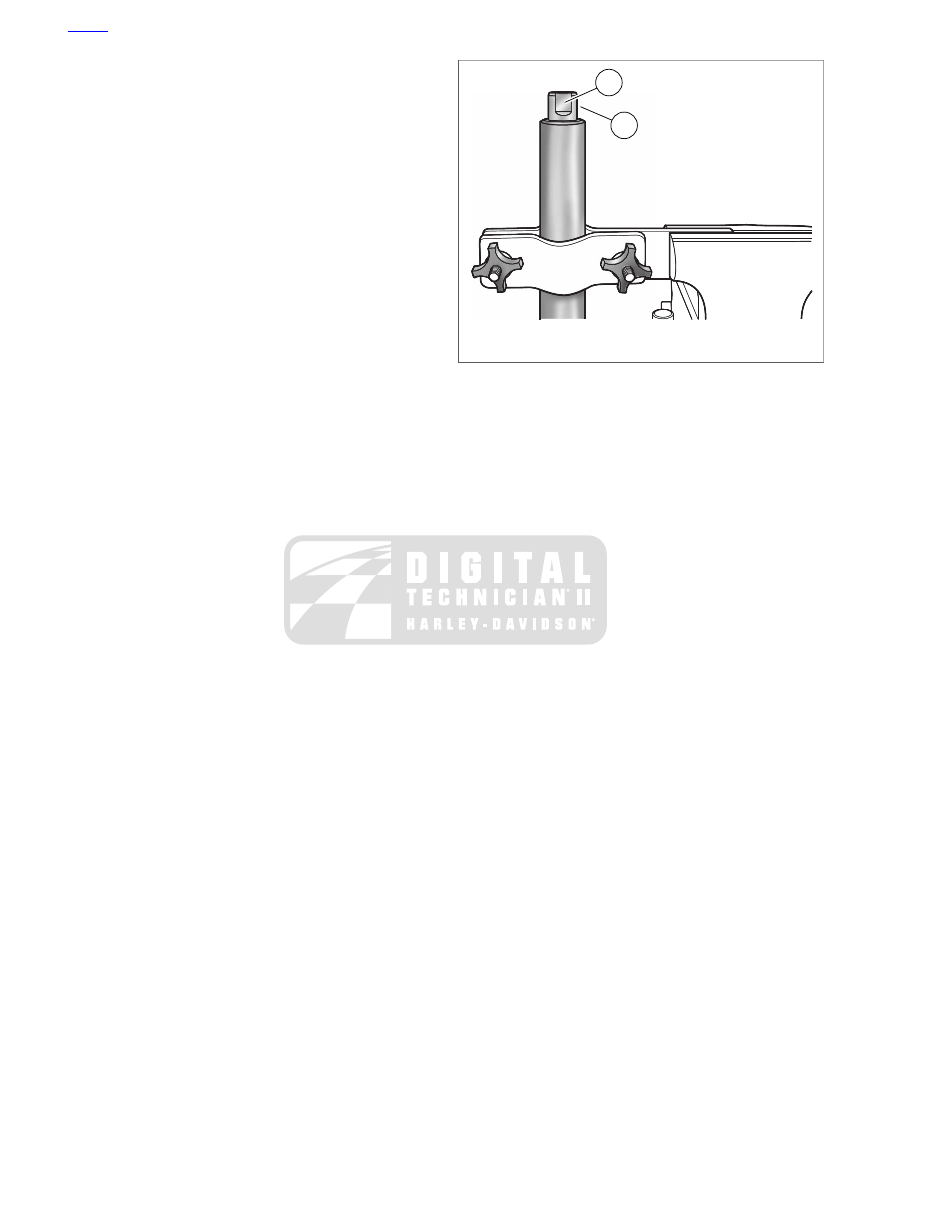
1

2

sm02898

1. Flat
2. Fork tube plug

Figure 2-56. Install Fork Tube Into Fork Holder

HOME

2-54 2011 Touring Service: Chassis

24

25

26

22

21

20

19

23

18

17

15

13

12

9

7

4

2

16

14

10

8

6

5

3

1

11

sm04820

14.

1.

Slider spacer

Fork cap bolt

2.

15.

Quad ring seal

Slider bushing

16.

3.

Fork leg bushing

Fork tube plug

4.

17.

O-ring

Lower stop

18.

5.

Fork slider

Spring

6.

19.

Damper valve (Fairing equipped only)

Plug

20.

7.

Flat washer

Wear ring (Fairing equipped only)

8.

21.

Wear ring

Copper washer

22.

9.

Screw (6mm)

Damper tube

10.

23.

Rebound spring

Axle holder

24.

11.

Flat washer (2)

Fork tube

12.

25.

Retaining clip

Lockwasher (2)

26.

13.

Nut (2)

Lip seal

Figure 2-57. Right Side Fork

CLEANING AND INSPECTION

1.

Thoroughly clean and inspect all parts. Replace any parts
that are bent, inoperative or obviously damaged.

2.

Inspect fork cap bolt quad ring seal and fork tube plug o-
ring for cuts, tears or signs of deterioration. Replace if
necessary.

3.

Replace retaining clip if bent or distorted.

4.

Check slider and fork leg bushings for scratches or
excessive wear. Always replace bushings in a set if either
bushing is damaged or worn.

HOME

2011 Touring Service: Chassis 2-55

sm02901

Figure 2-58. Measure Fork Tube Runout

5.

See

Figure 2-58

Check fork tube and slider for scoring,

scratches and excessive or abnormal wear. Replace parts
as necessary. Set fork tube on V-blocks and measure
runout using a dial indicator gauge. Replace fork if runout
exceeds 0.008 in. (0.2 mm).

6.

Inspect upper fork spring and rebound spring for damage
or distortion. Replace upper fork spring if free length is
less than:

a.

Non-Fairing Models:

19.27 in. (489.4 mm).

b.

Fairing Models:

18.73 in. (475.7 mm).

Replace rebound spring if free length is less than 0.938
in. (23.8 mm) or any time the upper fork spring is replaced.

ASSEMBLY

TOOL NAME

PART NUMBER

FORK OIL SEAL INSTALLER

HD-34634

FORK HOLDING TOOL

HD-41177

Exercise caution to avoid scratching or nicking fork tube.
Damaging tube can result in fork oil leaks after assembly.
(00421b)

1.

See

Figure 2-57

Coat ID of fork leg bushing (16) with

clean fork oil. Expand fork leg bushing at split line only
enough to slip over end and into groove of fork tube.

2.

Install

new

wear ring (8) in groove at top of damper tube

(9). Install rebound spring (10) on opposite end.

3.

With the wear ring topside, slide damper tube into fork
tube, so that tube end drops through hole at bottom of fork
tube. Install lower stop (17) at end of damper tube.

4.

Install fork slider in FORK HOLDING TOOL (Part No. HD-
41177). Slide fork tube into fork slider.

5.

Coat ID of slider bushing (15) with clean fork oil. Slide
slider bushing down fork tube.

6.

Slide FORK OIL SEAL INSTALLER (Part No. HD-34634)
down the fork tube, and using the tool like a slide hammer,
drive slider bushing into the counterbore of the fork slider.
Remove tool.

NOTE

Place masking tape over edge of fork tube to avoid damaging
lip of fork oil seal during installation.

7.

See

Figure 2-57

. Coat ID of

new

fork oil seal (13) with

clean fork oil. With the lip garter spring side facing down
(toward the fork slider), slide seal down fork tube until it
contacts slider spacer (14). Remove masking tape from
edge of fork tube.

8.

See

Figure 2-59

Using the tool like a slide hammer, drive

fork oil seal down fork tube until retaining clip groove is
visible in fork slider ID. Remove tool.

NOTE

Do not expand or stretch retaining clip to install on fork tube
or clip may become bent or distorted.

9.

See

Figure 2-57

Install retaining clip (12) in the fork slider

groove.

10. Install fork spring (5) into fork tube.

11. Remove fork assembly from fork holding tool.

is00157

Figure 2-59. Install Fork Oil Seal

12. Place a shop cloth on the floor. Turn fork assembly upside

down and press end of spring against rag to prevent
rotation of damper tube.

13. Install

new

screw (22) with

new

copper crush washer (21)

at bottom of fork slider.

14. While compressing spring, tighten screw to 132-216

in-

lbs

(14.9-24.4 Nm).

15. Remove fork spring from fork tube.

16. Fill fork and complete assembly. See

2.17 FRONT FORK,

Changing Fork Oil

.

17. On right side fork, loosely install axle holder with flat

washers, lockwashers and nuts on fork slider.

INSTALLATION

1.

Remove fork cap bolt.

2.

Slide fork tube up and into slider cover, lower fork bracket,
fork stop, and upper fork bracket. Install fork cap bolt.

HOME

2-56 2011 Touring Service: Chassis

3.

See

Figure 2-55

. Install pinch bolt (2) (with lockwasher)

in lower fork bracket. Tighten pinch bolt to 53-57 ft-lbs
(71.9-77.3 Nm).

4.

Tighten fork cap bolt (1) to 60-70 ft-lbs (81.4-94.9 Nm).

5.

Repeat previous steps on other fork, if removed.

6.

Install the front fender and wheel. See

2.45 FRONT

FENDER

and

2.4 FRONT WHEEL

.

7.

FLHR/C:

Install headlamp nacelle. See

2.44 HEADLAMP

NACELLE: ROAD KING MODELS

.

8.

FLHX, FLHTC/U, FLHTK:

Install fairing inner cap. See

2.35

FAIRING

CAP:

FORK

MOUNTED

FAIRING

MODELS

.

9.

FLTRX,

FLTRU:

Install

instrument

nacelle.

See

2.40 INSTRUMENT NACELLE: FRAME MOUNTED
FAIRING MODELS

.

HOME

2011 Touring Service: Chassis 2-57

2.18

STEERING HEAD BEARINGS

REMOVAL

TOOL NAME

PART NUMBER

UNIVERSAL DRIVER

HD-33416

STEERING HEAD BEARING CUP
REMOVER

HD-39301A

1.

Disassemble motorcycle as follows:

a.

FLHR/C:

Remove

headlamp

nacelle.

See

2.44 HEADLAMP NACELLE: ROAD KING MODELS

.

b.

FLHX, FLHTC/U, FLHTK:

Remove the auxiliary lamp

bracket, outer fairing and radio. See

7.13 AUXILIARY

LAMPS AND BRACKETS

,

2.34 UPPER FAIRING

AND WINDSHIELD: FORK MOUNTED FAIRING
MODELS

and

7.33 ADVANCED AUDIO SYSTEM

,

respectively.

c.

FLTRX, FLTRU:

Remove instrument nacelle. See

2.40 INSTRUMENT NACELLE: FRAME MOUNTED
FAIRING MODELS

.

2.

Remove front forks. See

2.17 FRONT FORK

.

9

5

10

11

12

13

8

8

7

6

4

3

2

1

sm05763

1. Fork stem nut
2. Hardened flat washer
3. Bracket
4. Upper fork bracket
5. Spade contact
6. Bearing adjuster nut
7. Dust shield
8. Bearing cone
9. Bearing cup
10. Dust shield
11. Lower fork bracket and stem assembly
12. Bushing (2) (FLHTC/U, FLHTK, FLHX)
13. Roll pin

Figure 2-60. Steering Head/Fork Bracket Assembly

2

1

sm02909

1. Remover
2. Collet

Figure 2-61. Steering Head Bearing Cup Remover (Part

No. HD-39301A)

HOME

2-58 2011 Touring Service: Chassis

sm02910

Figure 2-62. Universal Driver (Part No. HD-33416)

3.

Release brake line bracket from lower fork bracket.

4.

See

Figure 2-60

Remove fork stem nut (1) and hardened

flat washer (2).

NOTE

Bracket (3) does not need to be removed unless it or the upper
fork bracket are to be replaced.

5.

Disconnect ignition switch [33], left handlebar switch [24],
right handlebar switch [22] and twist grip sensor jumper
harness [204] connectors. On fairing equipped motor-
cycles, remove interconnect harness ground socket ter-
minal from spade contact at front of upper fork bracket
(left side).

6.

Remove upper fork bracket (4).

7.

Remove bearing adjuster nut (6).

8.

Using a rubber mallet, tap on stem of lower fork bracket
(11) and remove lower fork bracket.

9.

Remove dust shield (7) and upper bearing cone (8).

10. Remove lower bearing cone (8) and dust shield (10) from

stem of lower fork bracket.

11. See

Figure 2-63

With the tapered side down, seat

STEERING HEAD BEARING CUP REMOVER (Part
No. HD-39301A) on the upper bearing cup leaving a gap
in the middle.

12. See

Figure 2-61

. Install collet (2) on driver.

13. Insert UNIVERSAL DRIVER (Part No. HD-33416) driver

up through bottom of steering head, and while holding
remover tool on upper bearing cup, center collet in gap.
Tap driver to remove upper bearing cup.

14. Reverse tool and repeat procedure to remove lower

bearing cup.

4

3

2

1

sm02911

1. Install remover on upper cup
2. Install collet on driver
3. Install driver in remover and remove upper cup
4. Remove lower cup

Figure 2-63. Remove Steering Head Bearing Cups

INSPECTION

1.

Check the bearing races in the steering head. If pitted or
grooved, replace both the bearings and races.

2.

Turn bearings in races. Replace the bearings if they do
not move freely and smoothly. Always replace both races
and bearings even if one race and bearing appears good.

HOME

2011 Touring Service: Chassis 2-59

INSTALLATION

TOOL NAME

PART NUMBER

STEERING HEAD BEARING CUP
INSTALLER

HD-39302

Properly seat bearing cups in steering head bore. Improper
seating can loosen fork stem bearings adversely affecting
stability and handling, which could result in death or ser-
ious injury. (00302a)

NOTE

If bearing races are replaced, the bearing cones must also be
replaced.

1.

See

Figure 2-64

. If removed, install

new

bearing cups

using STEERING HEAD BEARING CUP INSTALLER (Part
No. HD-39302).

2.

See

Figure 2-60

If installing a

new

bracket and stem

assembly (11), press in

new

roll pin (13) and guide bush-

ings (12) (FLHTC/U, FLHTK, FLHX models only) as shown.
Be sure to install bushings with outer chamfer toward
bracket.

3.

Pack

new

bearing cones with Harley-Davidson SPECIAL

PURPOSE GREASE (Part No. 99857-97).

4.

Install

new

dust shield and bearing cone on fork stem

(both are installed on

new

bracket and stem assembly).

Be sure both are securely seated.

5.

Insert stem of lower fork bracket into steering head.

6.

Install upper bearing cone and

new

dust shield until flush

with top of steering head.

7.

Install bearing adjuster nut and snug until bearing play is
taken up and stem turns freely. Overtightening nut will
cause excessive bearing wear.

8.

Install upper fork bracket.

NOTE

The washer under the fork stem nut is a special hardened
material. Never replace this washer with a common flat washer.
Doing so may allow the fork stem nut to loosen resulting in loss
of steering control.

9.

Install hardened flat washer and stem nut. Do not tighten
stem nut at this time.

Properly adjust fork stem bearings. Improper adjustments
affect stability and handling, which could result in death
or serious injury. (00301a)

10. Adjust bearings. See

1.20 STEERING HEAD BEARINGS

.

sm04980

Figure 2-64. Install Steering Head Bearing Cups

11. Connect ignition switch [33], left handlebar switch [24],

right handlebar switch [22] and twist grip sensor jumper
harness [204] connectors. On fairing equipped motor-
cycles, connect interconnect harness ground socket ter-
minal to spade contact at front of upper fork bracket (left
side).

12. Install front forks. See

2.17 FRONT FORK

.

13. Attach brake line bracket to bottom of lower fork bracket.

Verify that brake lines to calipers are equal distance from
the left and right fork sliders. Tighten screw to 120-180

in-

lbs

(13.6-20.3 Nm).

14. Assemble motorcycle as follows:

a.

FLHR/C:

Install headlamp nacelle. See

2.44 HEAD-

LAMP NACELLE: ROAD KING MODELS

.

b.

FLHX, FLHTC/U, FLHTK:

Install radio, outer fairing

and auxiliary lamp bracket. See

7.33 ADVANCED

AUDIO SYSTEM

,

2.34 UPPER FAIRING AND

WINDSHIELD: FORK MOUNTED FAIRING MODELS

and

7.13 AUXILIARY LAMPS AND BRACKETS

,

respectively.

c.

FLTRX, FLTRU:

Install instrument nacelle. See

2.40 INSTRUMENT NACELLE: FRAME MOUNTED
FAIRING MODELS

.

HOME

2-60 2011 Touring Service: Chassis

2.19

REAR AIR SUSPENSION

CHECK FOR AIR LEAKS

TOOL NAME

PART NUMBER

AIR SUSPENSION PUMP AND GAUGE

HD-34633A

Use caution when bleeding air from the suspension.
Moisture combined with lubricant may leak onto the rear
wheel, tire and/or brake components and adversely affect
traction, which could result in death or serious injury.
(00084a)

NOTES

Remove and replace components as necessary to access
air suspension system components.

Always release air pressure from system before removing
any component from the suspension system. To purge
tubes of any oil, add 3-5 psi (20.7-34.5 kPa) before
releasing air.

1.

Verify that valve core is properly tightened and not leaking.

2.

Adjust air pressure using AIR SUSPENSION PUMP AND
GAUGE (Part No. HD-34633A). See

1.19 SUSPENSION

ADJUSTMENTS

.

3.

Apply a light film of soapy water on all compression fittings
at the top of each shock absorber and around the air valve
including the core area. Pressurize system.

a.

If leakage is evident, repair or replace damaged
components as necessary.

b.

If no leaks were evident at the fittings, inspect the air
tubes for damage that may result in air leaks. Apply
soapy water to the suspect area and look for leakage.

c.

If the tubes show no evidence of leakage, a damaged
shock absorber is likely the fault. Allow the motorcycle
to set overnight. If a loss of 5-10 psi (34.5-68.9 kPa)
is noted, replace the shock absorbers, one at a time,
and retest.

4.

Pressurize system and check for leaks when repairs are
completed.

5.

Install protective cap on air valve.

Compression Fitting

1.

Disconnect air tube and remove compression fitting from
shock absorber.

2.

Apply PIPE SEALANT WITH TEFLON to the threads of a

new

compression fitting and install. Tighten to 12-17 ft-lbs

(16.3-23.0 Nm).

3.

Insert the air tube and gently tug on tube to verify that it
is secure in fitting.

Air Valve Assembly

1.

See

Figure 2-65

. Remove hex nut (2).

2.

Remove Air inlet tee assembly (4).

3.

Install the air valve assembly and secure with hex nut (2)
(flat side facing inboard). Tighten nut to 40-50

in-lbs

(4.5-

5.6 Nm).

Air Tubes

1.

Remove the seat. See

2.25 SEAT

.

NOTE

Take note of air tube routing.

2.

Remove tubes from air valve assembly and shock
absorbers.

3.

Cut bulk tubing to proper length.

4.

Install

new

tubes into fittings following the original routing.

Gently tug on tube to verify that it is secure in fitting.

After installing seat, pull upward on seat to be sure it is
locked in position. While riding, a loose seat can shift
causing loss of control, which could result in death or
serious injury. (00070b)

5.

Install the seat. See

2.25 SEAT

.

HOME

2011 Touring Service: Chassis 2-61

8

4

2

1

6

5

7

3

sm05764

1. Protective cap
2. Hex nut
3. Air valve and mounting bracket
4. Air inlet tee
5. Shock air inlet tube
6. Air tube fitting
7. Left shock
8. Right shock

Figure 2-65. Rear Air Suspension System

HOME

2-62 2011 Touring Service: Chassis

2.20

REAR SHOCK ABSORBERS

REMOVAL

TOOL NAME

PART NUMBER

AIR SUSPENSION PUMP AND GAUGE

HD-34633

NOTE

If replacing both shock absorbers, remove and install one at a
time.

When lifting a motorcycle using a jack, be sure jack con-
tacts both lower frame tubes where down tubes and lower
frame tubes converge. Never lift by jacking on cross-
members, oil pan or other housings. Failure to comply can
cause serious damage resulting in the need to perform
major repair work. (00586c)

1.

Raise the motorcycle with a suitable lifting device until the
rear tire is just touching.

2.

Remove saddlebags. See

2.26 SADDLEBAGS

.

Use caution when bleeding air from the suspension.
Moisture combined with lubricant may leak onto the rear
wheel, tire and/or brake components and adversely affect
traction, which could result in death or serious injury.
(00084a)

3.

Bleed air from the system and remove the air tube from
the air tube fitting. To purge lines of any oil, add 3-5 psi
(20.7-34.5 kPa) using the no-loss AIR SUSPENSION
PUMP AND GAUGE (Part No. HD-34633) before releasing
air.

4.

Remove the upper shock absorber mounting bolt, lock-
washer and flat washer.

5.

Remove the lower mounting bolt, lockwasher and flat
washer. Remove the shock absorber assembly from the
motorcycle.

NOTE

Never lay the shock absorber down. Always keep the shock
absorber upright to prevent oil from draining out through the
compression fitting. Any loss of oil requires replacement of the
shock absorber.

CLEANING AND INSPECTION

1.

Examine the rubber mounting bushings for cracks or wear.
Examine the shock for leaks. The unit should not leak and
should compress slightly easier than it extends. Compare
the action of the shock with a

new

one to judge if it is worn.

Replace the shock if necessary.

2.

Clean and examine the shock mounting hardware. Replace
parts that are worn or damaged.

DISASSEMBLY AND ASSEMBLY

NOTE

Other than air tube fittings, air shocks are not repairable.
Replace the shocks if damaged, worn or any sign of leakage
is observed.

1.

If necessary, remove the air tube fitting form the shock
absorber.

2.

Apply PIPE SEALANT WITH TEFLON to the threads of a

new

air tube fitting and install. Tighten to 12-17 ft-lbs (16.3-

23.0 Nm).

INSTALLATION

NOTE

Never lay the shock absorber down. Always keep the shock
absorber upright to prevent oil from draining out through the
compression fitting. Any loss of oil requires replacement of the
shock absorber.

1.

Apply two or three drops of LOCTITE MEDIUM
STRENGTH THREADLOCKER 243 (blue) to threads of
each mounting bolt.

2.

Install lower shock mounting bolt, lockwasher and flat
washer. Tighten bolt to 35-40 ft-lbs (47.5-54.2 Nm).

3.

Install upper shock mounting bolt, lockwasher and flat
washer. Tighten bolt to 35-40 ft-lbs (47.5-54.2 Nm).

4.

Insert air tube into air tube fitting until it bottoms. Gently
tug on tube to verify that it is locked in place.

5.

Pressurize rear air suspension system and check for leaks.
See

1.19 SUSPENSION ADJUSTMENTS

and

2.19 REAR

AIR SUSPENSION

.

6.

Install saddlebags. See

2.26 SADDLEBAGS, Installation

.

HOME

2011 Touring Service: Chassis 2-63

2.21

REAR FORK

REMOVAL

1.

Raise the motorcycle with a suitable lifting device. Support
the rear of the transmission with a second jack or slide a
block of wood between the oil pan and frame cross
member to support the weight of the transmission once
the pivot shaft is removed.

2.

Remove rear wheel. See

2.5 REAR WHEEL

.

3.

Remove caliper and bracket from anchor weldment on
rear fork.

4.

Remove belt guard from bottom of left side fork.

5.

Loosen both lower shock absorber mounting bolts but do
not remove at this time.

6.

See

Figure 2-66

Remove two screws (1) to free rear fork

bracket (2) with foot rest from left side of motorcycle frame.

7.

Release rear brake line hose and rear wheel speed sensor
(if ABS equipped) from cable clips on right side of rear
fork.

8.

Remove plug from right side.

9.

See

Figure 2-67

Hold left side screw and remove right

side screw from end of pivot shaft. Remove outer spacer.

10. Using a suitable drift, tap pivot shaft toward left side of

motorcycle.

11. See

Figure 2-68

. Pull pivot shaft assembly with screw,

outer spacer, rubber mount and middle spacer out of
transmission mount and left side fork.

12. Remove lower shock absorber bolts and work rear fork

free of transmission mount and rear fork brackets.

13. Remove middle spacer from right side fork tube.

14. Remove rubber mount from right side.

1

2

3

sm05787a

1. Screws
2. Fork bracket
3. Plug

Figure 2-66. Rear Fork Mount Bracket

sm05788a

Figure 2-67. Right Side Mount

1

2

sm05789a

1. Screw, pivot shaft
2. Left mount

Figure 2-68. Left Side Mount and Pivot Shaft Assembly

DISASSEMBLY AND ASSEMBLY

TOOL NAME

PART NUMBER

REAR FORK BEARING INSTALLER

HD-45327

Bearing Removal

1.

See

Figure 2-69

Select a driver (1) slightly smaller than

the bearing spacer and a rod (2) long enough to allow
pressing through upper bearing. Slide socket extension
through the brake side bearing and install socket on
extension.

2.

Support the fork (4) in a press with brake anchor weldment
on top. Verify that assembly is square and the bearing
bore is completely vertical.

HOME

2-64 2011 Touring Service: Chassis

3

4

1

2

sm05792

1. Driver
2. Rod
3. Bearing/spacer assembly
4. Rear fork

Figure 2-69. Remove Rear Fork Bearing

3.

Center rod under ram and press bearing/spacer assembly
(3) from rear fork.

4.

Remove tools from rear fork. Turn fork over and press out
brake side bearing in same manner.

5.

If bearings are to be replaced with

new

, press bushings

out and retain for later use.

Bearing Installation

1.

Assemble

new

rear fork bearings as follows:

a.

Place bearing flat on suitable press plate.

b.

See

Figure 2-70

. With the collar topside, start spacer

into bearing.

c.

Press spacer until it bottoms against press plate.

2

1

sm02930

1. Spacer
2. Bearing

Figure 2-70. Press Spacer into Bearing

2

1

sm03535

1. Drive side driver
2. Brake side driver

Figure 2-71. Rear Fork Bearing Installer

1

2

sm05793

1. Bearing installer
2. Fork tube

Figure 2-72. Install Rear Fork Bearing (typical)

2.

Coat the bearing bores in the rear fork with a light coat of
Special Purpose Grease (Part No. 99857-97).

3.

See

Figure 2-72

Support fork squarely on press bed with

the brake anchor weldment on top.

4.

Insert bearing into fork assembly with spacer down.

5.

Using REAR FORK BEARING INSTALLER (Part No. HD-
45327) (1) stamped "Brake Side", center driver under ram
and press on bearing until shoulder on tool makes contact
with fork tube (2).

6.

Remove tool and turn rear fork over. Repeat process with
remaining bearing using tool stamped "Drive Side". Press
bearing until it bottoms. Shoulder on tool will

not

make

contact with fork tube.

Pivot Shaft/Mount Disassembly

1.

See

Figure 2-73

Remove screw (7).

2.

Remove outer spacer (6), rubber mount (5) and middle
spacer (4).

HOME

2011 Touring Service: Chassis 2-65

1

2

3

4

5

6

7

8

sm05795a

1. Rear fork assembly
2. Bearing/spacer assembly
3. Pivot shaft
4. Middle spacer
5. Mount
6. Outer spacer
7. Screw
8. Fork bracket

Figure 2-73. Pivot Shaft Components

INSTALLATION

1.

See

Figure 2-74

. With the slot on the outboard side

between the twelve and one o'clock positions, install rubber
mount on inner-right side of frame. Be sure that index tab
in mount cavity fully engages slot in rubber mount.

2.

Place middle spacer into right side fork tube.

3.

Hold middle spacer in fork tube and move the fork into
approximate position. Loosely install lower shock absorber
screws.

4.

Work the rear fork into position between the transmission
mount and the right-rear fork mount. If necessary, carefully
tap fork into position using a rubber mallet.

5.

Coat pivot shaft with SILVER GRADE ANTI-SEIZE (Part
No. 98960-97). Avoid getting anti-seize on threads of pivot
shaft.

6.

See

Figure 2-68

. Slide pivot shaft from left side of motor-

cycle through left side fork and transmission mount. Guide
end of pivot shaft through hole in right rubber mount.

7.

See

Figure 2-73

Slide middle spacer (4) onto left end of

pivot shaft (3) until seated on shoulder of shaft.

8.

Install left rubber mount (5) with the flat side inboard
toward outer spacer.

9.

Install outer spacer (6).

10. See

Figure 2-66

Rotate the left rubber mount so the slot

is between the eleven and twelve o'clock positions. Install
left side fork bracket (2) fitting index tab into rubber mount
slot.

11. Apply two drops of Loctite Medium Strength Threadlocker

243 (blue) to threads of fork bracket screws (1) and secure
left side fork bracket. Tighten screws to 55-65 ft-lbs (74.6-
88.1 Nm). Remove plug (3) from left side.

12. See

Figure 2-67

. Apply two drops of Loctite Medium

Strength Threadlocker 243 (blue) to threads of both pivot
shaft screws and install.

13. Tighten both screws to 55-65 ft-lbs (74.6-88.2 Nm).

14. Verify that rear fork assembly moves freely.

15. Install plugs.

16. Remove lower shock mounting bolts and apply two or

three drops of Loctite Medium Strength Threadlocker 243
(blue) to threads. Install bolts and tighten to 35-40 ft-lbs
(47.5-54.2 Nm).

17. Install belt guard.

18. Seat caliper bracket on anchor weldment of rear fork.

19. Capture rear brake line hose in two cable clips at top of

right side fork. Rear cable clip also captures rear wheel
speed sensor cable on ABS equipped motorcycles.

20. Install rear wheel. See

2.5 REAR WHEEL

.

sm05797

Figure 2-74. Right-Side Mount

HOME

2-66 2011 Touring Service: Chassis

2.22

CLUTCH CABLE

REMOVAL

To prevent accidental vehicle start-up, which could cause
death or serious injury, remove main fuse before pro-
ceeding. (00251b)

1.

Remove the main fuse.

2.

Remove right side exhaust system. See

4.19 EXHAUST

SYSTEM

.

3.

See

Figure 2-75

Slide rubber boot off clutch cable

adjuster. Loosen jam nut. Back away from cable adjuster.
Move adjuster toward jam nut to introduce free play at
hand lever.

4.

See

Figure 2-76

. Remove retaining ring from pivot pin

groove at bottom of clutch lever bracket. Remove pivot
pin.

5.

Remove clutch hand lever from clutch lever bracket. If
necessary, remove handlebar clamp from clutch lever
bracket.

6.

Remove anchor pin and clutch cable eyelet from clutch
hand lever.

7.

Remove the magnetic drain plug at the bottom right side
of the oil pan and drain the transmission lubricant into a
suitable container. Remove the filler plug/dipstick.

8.

Remove and disassemble clutch release cover. Remove
and discard gasket. See

6.5 CLUTCH RELEASE COVER

.

4

3

2

1

sm02219

1. Rubber boot
2. Cable adjuster
3. Jamnut
4. Cable end

Figure 2-75. Clutch Cable Adjuster

1

10

2

3

4

5

7

8

9

11

12

6

sm04655

1. Retaining ring
2. Pivot pin
3. Clutch lever bracket
4. Hand lever
5. Bushing
6. Anti-rattle spring and screw
7. Screw
8. Flat washer
9. Handlebar clamp
10. Anchor pin
11. Clutch cable
12. O-ring

Figure 2-76. Clutch Hand Lever Assembly

9.

See

Figure 2-79

Cut cable strap to free clutch cable from

right frame downtube. Continue as follows:

a.

Road King models:

See

Figure 2-77

Remove acorn

nut to release P-clamp from stud in upper fork bracket.
Remove clutch cable from P-clamp.

b.

Fork mounted fairing models:

See

Figure 2-78

.

Remove outer fairing. See

2.34 UPPER FAIRING

AND WINDSHIELD: FORK MOUNTED FAIRING
MODELS

Cut cable strap to release clutch cable from

left fairing bracket.

c.

Frame mounted fairing models:

Release clutch

cable from cable clip anchored in hole on left side of
instrument nacelle.

10. Remove clutch cable from motorcycle.

INSTALLATION

1.

See

Figure 2-76

. Insert clutch cable eyelet into groove of

clutch hand lever aligning eyelet with hole without bushing.
Insert anchor pin through lever and eyelet.

2.

Insert lever into groove of clutch lever bracket fitting sleeve
at end of cable housing into bore on inboard side of
bracket.

3.

Align hole in hand lever with hole in bracket and install
pivot pin. Install retaining ring in pivot pin groove.

HOME

2011 Touring Service: Chassis 2-67

4.

If removed, secure handlebar clamp to clutch lever bracket.
Starting with the top screw, tighten screws to 72-108

in-

lbs

(8.1-12.0 Nm).

5.

Start clutch cable routing as follows:

a.

Road King models:

See

Figure 2-77

Capture clutch

cable in P-clamp (1) and secure to upper fork bracket
with acorn nut (2). Route cable downward between
engine guard and front of left frame downtube.

b.

Fork mounted fairing models:

See

Figure 2-78

.

Feed clutch cable through grommet on left side of
inner fairing. Route cable on inboard side of left fairing
bracket between upper and lower wings of radio (or
storage box) support bracket. Secure cable to the
oblong hole of left fairing bracket using a cable strap.
Route cable downward between engine guard and
front of left frame downtube. Install the outer fairing.
See

2.34 UPPER FAIRING AND WINDSHIELD:

FORK MOUNTED FAIRING MODELS

.

c.

Frame mounted fairing models:

Capture clutch

cable in cable clip and anchor clip in hole on left side
of instrument nacelle. Route cable forward and then
rearward beneath instrument nacelle following left
side of the steering head. Route cable downward
between engine guard and front of left frame down-
tube.

1

2

sm04985

1. P-clamp
2. Acorn nut

Figure 2-77. FLHR/C Clutch Cable Routing (Left Side View)

sm04746

Figure 2-78. Secure Clutch Cable to Fairing Bracket

1

2

sm04745

1. Cable strap
2. Right frame downtube

Figure 2-79. Clutch Cable Routing (Right Side View)

6.

See

Figure 2-79

. Route the cable down and between

voltage regulator and right frame downtube. Secure cable
to downtube using a cable strap through the hole in the
crossbrace. Follow the inboard side of the frame downtube,
between the cam cover and the lower frame tube.

7.

Assemble and install clutch release cover with

new

gasket.

See

6.5 CLUTCH RELEASE COVER

.

8.

Check O-ring on the transmission drain plug for tears, cuts
or general deterioration. Replace as necessary.

9.

Install transmission drain plug. Tighten to 14-21 ft-lbs
(19.0-28.5 Nm).

10. Fill transmission. See

1.10 TRANSMISSION LUBRICANT

.

HOME

2-68 2011 Touring Service: Chassis

1

6

4

3

2

5

sm03668

Figure 2-80. Clutch Release Cover Torque Sequence (Short

Screws at Locations 1 and 6)

11. Adjust the clutch cable. See

1.11 CLUTCH

.

12. Install right side exhaust system. See

4.19 EXHAUST

SYSTEM

.

13. Install the main fuse.

HOME

2011 Touring Service: Chassis 2-69


Content      ..     12      13      14      15     ..