Harley Davidson 2011 Touring Models. Service Manual - page 13
 

  Главная      Harley Davidson     Harley Davidson 2011 Touring Models. Service Manual


Search            copyright infringement  


Content      ..     11      12      13      14     ..


Harley Davidson 2011 Touring Models. Service Manual - page 13


2

3

4

14

1

8

7

9

13

12

11

10

5

6

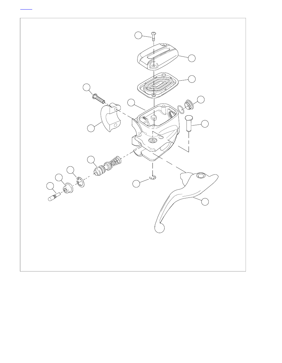
sm05012

8.

1.

Pivot pin

Master cylinder reservoir

2.

9.

Cover screw (2)

Brake hand lever

10.

3.

Pushrod

Cover

4.

11.

Gasket

Dust boot

12.

5.

Retaining ring

Clamp screw (2)

6.

13.

Handlebar clamp

Piston assembly

14.

7.

Sight glass/O-ring

Retaining ring

Figure 2-44. Front Brake Master Cylinder Assembly

HOME

2-38 2011 Touring Service: Chassis

CLEANING AND INSPECTION

Use denatured alcohol to clean brake system components.
Do not use mineral-based solvents (such as gasoline or
paint thinner), which will deteriorate rubber parts even
after assembly. Deterioration of these components can
cause brake failure, which could result in death or serious
injury. (00291a)

Compressed air can pierce the skin and flying debris from
compressed air could cause serious eye injury. Wear
safety glasses when working with compressed air. Never
use your hand to check for air leaks or to determine air
flow rates. (00061a)

1.

Clean all parts with denatured alcohol. Wipe dry with a
clean, lint free cloth.

2.

Inspect banjo seating surface for scratches or nicks.

3.

Verify that reservoir is completely free of dust, dirt or
residue.

4.

Using a clean air supply, blow out piston bore and other
drilled passages. Do not use a wire or similar instrument.

5.

Inspect piston bore for scratches, nicks, scoring, pitting,
corrosion or other damage.

6.

Inspect retaining ring for wear or distortion. Inspect
retaining ring groove for damage.

7.

Inspect piston seals, dust boot and reservoir cover gasket
for cuts, tears or general deterioration.

ASSEMBLY AND INSTALLATION

Assembly

1.

See

Figure 2-44

. Lightly lubricate piston bore and OD of

piston seals with D.O.T. 4 brake fluid.

NOTE

Never install a used piston assembly or spring because unex-
pected failure can occur. Always install new parts.

2.

Insert spring end of

new

piston assembly (13) into piston

bore.

3.

Push on piston assembly to compress spring and install
retaining ring (12) with the flat side in. Verify that retaining
ring is completely seated in groove.

4.

Install dust boot (11) onto pushrod (10) until it engages
groove in pushrod.

5.

Install pushrod into piston socket and engage dust boot
into piston bore. Verify that collar on OD of dust boot is
secure in lip of piston bore.

Installation

1.

See

Figure 2-45

. Place a dab of G-40M grease (Part No.

42820-04) into pocket of hand lever.

2.

Install brake hand lever and secure with pivot pin.

3.

Install

new

retaining ring in pivot pin groove. Verify that

retaining ring is completely seated in groove.

4.

Place cardboard insert between brake lever and brake
lever bracket. Use the eyelet of an ordinary cable strap if
the cardboard insert is not available.

5.

See

Figure 2-43

. Position brake lever/master cylinder

reservoir assembly, engaging tab (1) in groove (2) at top
of brake lever bracket.

6.

Install two screws (with flat washers). Position for rider
comfort. Beginning with the top screw, tighten screws to
72-108

in-lbs

(8.1-12.2 Nm).

7.

Secure brake line to master cylinder reservoir using

new

copper washers. Tighten banjo bolt to master cylinder to
12.5-14.5 ft-lbs (16.9-19.7 Nm).

Any time the ABS module, either master cylinder, or any
line between a master cylinder and the ABS module is
disconnected or replaced, Digital Technician II must be
used during the brake bleeding procedure to verify all air
is removed from the system. Failure to do so could result
in air in the hydraulic brake system, reducing brake effi-
ciency, which could result in death or serious injury.
(00585b)

8.

Fill and bleed brake system. See

2.16 BLEEDING

BRAKES

.

2

1

sm05015

1. Pushrod
2. Lever pocket

Figure 2-45. Apply Grease to Lever Pocket

FRONT BRAKE LINE: NON-ABS EQUIPPED

Removal

NOTE

For service of ABS equipped vehicles, see

C.4 ABS BRAKE

LINES

.

HOME

2011 Touring Service: Chassis 2-39

1.

Road King models:

a.

Remove

right

side

headlamp

nacelle.

See

2.44 HEADLAMP NACELLE: ROAD KING MODELS

.

b.

See

Figure 2-46

Cut cable strap from right handlebar

riser.

c.

See

Figure 2-47

. Cut cable strap from brake hose.

2.

Fork mounted fairing models:

a.

Remove

outer

fairing

and

fairing

cap.

See

2.34 UPPER FAIRING AND WINDSHIELD: FORK
MOUNTED FAIRING MODELS

and

2.35 FAIRING

CAP: FORK MOUNTED FAIRING MODELS

.

b.

Cut cable strap to release right handlebar switch
conduit and brake line from right handlebar.

c.

See

Figure 2-47

. Cut cable strap.

3.

Frame mounted fairing models:

a.

Remove

right

side

instrument

nacelle.

See

2.40 INSTRUMENT NACELLE: FRAME MOUNTED
FAIRING MODELS

.

b.

If present, remove P-clip securing brake line to front
right side of upper fork bracket.

4.

Remove front brake line bracket from bottom of lower fork
bracket.

5.

Turn handlebars until the master cylinder reservoir is level.

NOTE

Thoroughly clean the cover before removal to prevent contam-
ination.

6.

Remove cover from master cylinder reservoir.

NOTE

Wrap banjo fittings with a shop towel to absorb any loss of
brake fluid.

7.

Remove banjo bolt from master cylinder. Hold suitable
container under banjo bolt bore and allow reservoir to
drain. Discard copper washers.

8.

Wipe out remaining fluid in the master cylinder reservoir
using a clean shop cloth.

9.

Disconnect brake lines from both front brake calipers.
Discard copper washers.

10. Remove front brake line from motorcycle.

sm03522

Figure 2-46. Capture Brake Hose and Right Handlebar

Riser (FLHR/C)

sm03520

Figure 2-47. Capture Brake Hose and Front Fender Tip

Lamp Wires

Installation

1.

Position the front brake line bracket at the bottom of the
lower fork bracket and loosely attach with screw.

2.

Verify that brake lines are equal distance from the left and
right fork sliders, and tighten screw to 120-180

in-lbs

(13.6-20.3 Nm).

3.

Secure brake line to master cylinder reservoir using

new

copper washers. Tighten banjo bolt to 12.5-14.5 ft-lbs
(16.9-19.7 Nm)

4.

Secure brake lines to brake calipers using

new

copper

washers. Tighten banjo/bleeder bolts to 17-19 ft-lbs (23.1-
25.8 Nm).

5.

Fill and bleed brake system. See

2.16 BLEEDING

BRAKES

.

HOME

2-40 2011 Touring Service: Chassis

6.

Road King models:

a.

See

Figure 2-46

Secure right handlebar switch har-

ness and brake hose to right handlebar riser with

new

cable strap.

b.

Install right side headlamp nacelle. See

2.44 HEAD-

LAMP NACELLE: ROAD KING MODELS

.

c.

See

Figure 2-47

. Secure front fender tip lamp wires

to left brake caliper hose with

new

cable strap.

7.

Fork mounted fairing models:

a.

Just outboard of fairing cap opening, install

new

cable

strap to secure right handlebar switch harness and
brake line to right handlebar.

b.

Install fairing cap and outer fairing. See

2.35 FAIRING

CAP: FORK MOUNTED FAIRING MODELS

and

2.34 UPPER FAIRING AND WINDSHIELD: FORK
MOUNTED FAIRING MODELS

.

c.

See

Figure 2-47

Secure front fender tip lamp wires

to left brake caliper hose with

new

cable strap.

8.

Frame mounted fairing models:

a.

If present, capture brake line in P-clip and secure with
hex screw to upper fork bracket.

b.

Install

right

side

instrument

nacelle.

See

2.40 INSTRUMENT NACELLE: FRAME MOUNTED
FAIRING MODELS

.

HOME

2011 Touring Service: Chassis 2-41

2.13

FRONT BRAKE CALIPER

REMOVAL

NOTES

If only replacing brake pads, see

1.16 BRAKE PADS AND

DISCS

.

Wrap banjo fitting with a shop towel to absorb any loss of
brake fluid.

1.

Remove banjo bleeder bolt. Discard copper washers.

2.

See

Figure 2-48

. Remove two caliper mounting screws

(2) and remove caliper from brake disc.

1

3

4

2

7

6

5

sm04988

1. Caliper
2. Caliper mounting screw
3. Screen
4. Retaining clip
5. Pad pin
6. Brake pads
7. Pad spring

Figure 2-48. Front Brake Caliper Assembly

INSTALLATION

1.

If necessary, assemble caliper installing pad spring, brake
pads, pad pin, retaining clip and screen. See

1.16 BRAKE

PADS AND DISCS

.

2.

Install caliper, with cable clip/bracket on left side if ABS
equipped, and start two mounting screws. Tighten to 28-
38 ft-lbs (37.9-51.5 Nm).

3.

If ABS equipped, verify wheel speed sensor is secure in
clip.

4.

If ABS equipped, install two

new

cable straps as follows:

a.

Install cable strap 2.5 in. (63.5 mm) above the bottom
brake hose crimp capturing front wheel speed sensor
cable and brake hose.

b.

Install cable strap 2.5 in. (63.5 mm) below the top
brake hose crimp capturing front wheel speed sensor
cable, brake hose and front fender tip lamp wires, if
equipped.

5.

Secure brake line to caliper with banjo bleeder bolt and

new

copper washers. Tighten bolt to 17-19 ft-lbs (23.1-

25.8 Nm).

NOTE

When removing or replacing a bleeder valve or banjo bleeder
bolt, an O-ring might be present that is used during manufac-
turing. Remove the O-ring from the bleeder valve groove or
bore and discard. If care is not taken to remove and discard
the O-ring, it may become lodged in the bleeder bore during
valve installation and prevent proper torquing or sealing.

6.

Fill and bleed brake system. See

2.16 BLEEDING

BRAKES

.

HOME

2-42 2011 Touring Service: Chassis

2.14

REAR BRAKE MASTER CYLINDER

GENERAL

Direct contact of D.O.T. 4 brake fluid with eyes can cause
irritation. Avoid eye contact. In case of eye contact flush
with large amounts of water and get medical attention.
Swallowing large amounts of D.O.T. 4 brake fluid can cause
digestive discomfort. If swallowed, obtain medical atten-
tion. Use in well ventilated area. KEEP OUT OF REACH OF
CHILDREN. (00240a)

D.O.T. 4 brake fluid will damage painted and body panel
surfaces it comes in contact with. Always use caution and
protect surfaces from spills whenever brake work is per-
formed. Failure to comply can result in cosmetic damage.
(00239b)

Do not allow dirt or debris to enter the master cylinder
reservoir. Dirt or debris in the reservoir can cause improper
operation and equipment damage. (00205c)

NOTE

Immediately wipe up any brake fluid spillage with a clean, dry,
soft cloth. Follow up by thoroughly wiping affected area with a
clean, damp, soft cloth (small spills) or washing with a large
quantity of soapy water (large spills).

REMOVAL AND DISASSEMBLY

Removal

1.

Remove right lower fairing, if present. See

2.33 LOWER

FAIRING AND ENGINE GUARD

.

2.

Remove right side rider footboard. See

2.49 FOOT-

BOARDS AND FOOTRESTS

.

3.

Stand motorcycle upright, so that rear master cylinder
reservoir is level.

4.

To prevent dirt and other contaminants from entering the
master cylinder reservoir, thoroughly clean the cover
before removal.

5.

Remove cover from master cylinder reservoir.

HOME

2011 Touring Service: Chassis 2-43

1

6

2

3

5

4

sm05022

4.

1.

Cotter pin

Rear brake pedal

2.

5.

O-ring (2)

Flat washer

6.

3.

Master cylinder reservoir

Clevis pin

Figure 2-49. Rear Master Cylinder/Brake Pedal Assembly

NOTE

Wrap banjo fitting with piece of shop towel to absorb any loss
of brake fluid.

6.

Remove brake line from master cylinder reservoir. Hold
suitable container under banjo bolt bore to allow reservoir
to drain. Discard copper washers.

7.

Using a clean shop cloth, wipe out any remaining fluid in
the master cylinder reservoir.

8.

Remove master cylinder from engine mount end cap.

9.

Remove locknut with flat washer and pull brake
pedal/master cylinder assembly from pedal shaft. Remove
and discard O-ring on each side of brake pedal shaft bore.

10. See

Figure 2-49

Remove cotter pin and flat washer from

clevis pin. Remove clevis pin to separate master cylinder
assembly from brake pedal flange.

Disassembly

NOTE

Exercise care to avoid scratching or nicking banjo sealing
surface during handling. Damage to the sealing surface
requires replacement of the master cylinder reservoir.

1.

See

Figure 2-50

Remove dust boot (9) from reservoir

pulling it over slotted end of pushrod.

2.

Pushing down on flat washer (11) to compress pedal return
spring (12), remove E-clip (10) from groove in pushrod,
and then carefully release spring.

3.

Remove flat washer and pedal return spring from pushrod.

4.

Push on end of piston to remove tension and remove
retaining ring (13) from groove in piston bore.

5.

Remove pushrod (15) and special washer (14).

6.

Pull piston assembly from piston bore.

HOME

2-44 2011 Touring Service: Chassis

14

15

4

3

16

12

6

9

10

11

5

1

2

13

7

8

17

sm05021

10.

1.

E-clip

Master cylinder reservoir

2.

11.

Cover screw (2)

Flat washer

12.

3.

Pedal return spring

Cover

4.

13.

Gasket

Retaining ring

14.

5.

Special washer

Screw (2)

6.

15.

Cotter pin

Pushrod

16.

7.

Piston assembly

Flat washer

8.

17.

Clevis pin

Sight glass/O-ring

9. Dust boot

Figure 2-50. Rear Brake Master Cylinder Assembly

HOME

2011 Touring Service: Chassis 2-45

CLEANING AND INSPECTION

Use denatured alcohol to clean brake system components.
Do not use mineral-based solvents (such as gasoline or
paint thinner), which will deteriorate rubber parts even
after assembly. Deterioration of these components can
cause brake failure, which could result in death or serious
injury. (00291a)

Compressed air can pierce the skin and flying debris from
compressed air could cause serious eye injury. Wear
safety glasses when working with compressed air. Never
use your hand to check for air leaks or to determine air
flow rates. (00061a)

1.

Clean all parts with denatured alcohol. Wipe dry with a
clean, lint free cloth.

2.

Inspect banjo seating surface for scratches or nicks.

3.

Verify that reservoir is completely free of dust, dirt or
residue.

4.

Using a clean air supply, blow out piston bore and other
drilled passages. Do not use a wire or similar instrument.

5.

Inspect piston bore for scratches, nicks, scoring, pitting,
corrosion or other damage.

6.

Inspect retaining ring and E-clip for wear or distortion.
Inspect retaining ring and E-clip grooves for damage.

7.

Inspect springs for stretching, distortion, kinks, cracks or
broken coils.

8.

Inspect piston seals, dust boot and reservoir cover gasket
for cuts, tears or general deterioration.

ASSEMBLY AND INSTALLATION

Assembly

1.

Lightly lubricate piston bore and OD of piston seals with
D.O.T. 4 brake fluid.

2.

Insert spring end of piston assembly into piston bore.

3.

Slide special washer and retaining ring over pushrod.
Collar on ID of special washer should face slotted end of
pushrod, while flat side of retaining ring should face ball
end.

4.

Use ball end of pushrod to compress spring and install
retaining ring in groove of piston bore. Verify that retaining
ring is completely seated in groove.

5.

Slide pedal return spring over pushrod until larger diameter
coil is seated on retaining ring in piston bore.

6.

Slide flat washer over pushrod until seated on smaller
diameter coil of pedal return spring.

7.

Using a suitable spring compressor, compress pedal return
spring and install E-clip in inboard groove of pushrod.

8.

Slide open end of dust boot over pushrod and onto reser-
voir until ID on closed end is captured in outboard groove
of pushrod.

Installation

1.

Install master cylinder assembly onto brake pedal flange.
Install clevis pin from the outboard side. Install flat washer
and cotter pin on clevis pin.

2.

Apply a light coat of Wheel Bearing Grease (Part No.
99855-89) to the brake pedal shaft and bore. Install

new

O-ring on each side of bore.

3.

Install brake pedal/master cylinder assembly on the pedal
shaft. Install flat washer and

new

locknut on pedal shaft.

4.

Install two screws to secure master cylinder. Tighten
screws to 126-150

in-lbs

(14.2-17.0 Nm).

5.

Tighten brake pedal shaft locknut to 15-20 ft-lbs (20.3-27.1
Nm).

6.

Start banjo bolt (with

new

copper washers) to secure brake

line to master cylinder reservoir. Tighten banjo bolt to 12.5-
14.5 ft-lbs (16.9-19.7 Nm).

Any time the ABS module, either master cylinder, or any
line between a master cylinder and the ABS module is
disconnected or replaced, Digital Technician II must be
used during the brake bleeding procedure to verify all air
is removed from the system. Failure to do so could result
in air in the hydraulic brake system, reducing brake effi-
ciency, which could result in death or serious injury.
(00585b)

7.

Fill and bleed brake system. See

2.16 BLEEDING

BRAKES

.

8.

Install right side rider footboard. See

2.49 FOOTBOARDS

AND FOOTRESTS

.

REAR BRAKE LINE: NON-ABS EQUIPPED

Removal

1.

Remove right side saddlebag. See

2.26 SADDLEBAGS

.

2.

Remove right side cover.

3.

Remove right lower fairing, if present. See

2.33 LOWER

FAIRING AND ENGINE GUARD

.

4.

Remove right side rider footboard. See

2.49 FOOT-

BOARDS AND FOOTRESTS

.

5.

See

Figure 2-51

Free rear brake line from electrical har-

ness conduit clips (6).

6.

Remove socket terminals from rear brake light switch (4)
spade contacts. Cut cable strap to free rear brake light
switch wires from lower frame tube, if necessary.

7.

Remove fastener (5) and brake light switch bracket from
frame.

8.

Free rear brake line hose from cable clips (3) on rear fork.

9.

Stand motorcycle upright, so that rear master cylinder
reservoir is level.

HOME

2-46 2011 Touring Service: Chassis

NOTE

To prevent dirt and other contaminants from entering the master
cylinder reservoir, thoroughly clean the cover before removal.

10. Remove cover from master cylinder reservoir.

NOTE

Wrap banjo fittings with pieces of shop towel to absorb any
loss of brake fluid.

11. Remove banjo bolt (12) from master cylinder reservoir.

Hold suitable container under banjo bolt bore to allow
reservoir to drain. Discard sealing washers (11).

12. Using a clean shop cloth, wipe out any remaining fluid in

the master cylinder reservoir.

13. Remove screws (10) securing master cylinder to frame.

14. Remove locknut (8) with flat washer (7) and pull brake

pedal/master cylinder assembly from pedal shaft. Remove
and discard O-rings (9).

15. Remove banjo bolt (2) from rear brake caliper. Discard

sealing washers (1).

16. Feed rear brake line hose forward to area in front of rear

fork bracket. Remove rear brake line from motorcycle.

1

2

3

4

6

5

8

7

9

9

11

10

12

sm05756

7.

1.

Flat washer

Sealing washers

2.

8.

Banjo bolt

Locknut

9.

3.

O-ring

Cable clips

4.

10.

Rear brake light switch

Fastener

11.

5.

Sealing washers

Fastener

6.

12.

Electrical harness conduit clips

Banjo bolt

Figure 2-51. Rear Brake Line Assembly

HOME

2011 Touring Service: Chassis 2-47

Installation

1.

Place rear brake line into approximate position along top
of lower right frame tube. From area in front of rear fork
bracket, feed brake line hose rearward following top of
rear fork.

2.

Move front section of brake line inboard of frame at bottom
of front frame downtube.

3.

See

Figure 2-51

. Secure brake line to caliper using

new

sealing washers.

4.

Capture rear brake line hose in two cable clips (3) on rear
fork.

NOTE

If installing new rear brake light switch, apply Loctite Pipe
Sealant with Teflon 565 to threads and start switch into rear
brake line. Using flats on switch, tighten to 12-15 ft-lbs (16.3-
20.3 Nm).

5.

Index locating tab on brake light switch bracket in slot of
frame. Install fastener (5) and tighten to 80-100

in-lbs

(9.0-11.3 Nm).

6.

Install terminals onto rear brake light switch (4). If removed,
install

new

cable strap to secure rear brake light switch

wires.

7.

Capture rear brake line to electrical harness conduit clips
(6).

8.

Apply a light coat of Wheel Bearing Grease (Part No.
99855-89) to the brake pedal shaft and bore. Install

new

O-rings (9) on each side of bore.

9.

Install brake pedal/master cylinder assembly on the pedal
shaft. Install flat washer (7) and

new

locknut (8) on pedal

shaft.

10. Fasten master cylinder to frame. Tighten screws to 126-

150

in-lbs

(14.2-17.0 Nm).

11. Tighten brake pedal shaft locknut to 15-20 ft-lbs (20.3-27.1

Nm).

12. Secure brake line to master cylinder reservoir using

new

sealing washers. Tighten banjo bolt to 12.5-14.5 ft-lbs
(16.9-19.7 Nm).

13. Tighten banjo bolt to brake caliper to 17-19 ft-lbs (23.1-

25.8 Nm).

14. Fill and bleed brake system. See

2.16 BLEEDING

BRAKES

.

15. Install right side rider footboard. See

2.49 FOOTBOARDS

AND FOOTRESTS

.

16. Install right lower fairing, if present. See

2.33 LOWER

FAIRING AND ENGINE GUARD

.

17. Install right side cover.

18. Install right side saddlebag. See

2.26 SADDLEBAGS

.

HOME

2-48 2011 Touring Service: Chassis

2.15

REAR BRAKE CALIPER

REMOVAL

NOTE

If only replacing brake pads, see

1.16 BRAKE PADS AND

DISCS

.

1.

Remove right side saddlebag. See

2.26 SADDLEBAGS

.

NOTE

Wrap banjo fitting with piece of shop towel to absorb any loss
of brake fluid.

2.

Remove banjo bolt to release brake line from caliper.
Discard copper washers.

3.

See

Figure 2-52

Remove two screws (2) to release caliper

from caliper bracket.

4.

Remove caliper from brake disc.

5.

If necessary, retract rear axle to remove caliper bracket
(3). See

2.5 REAR WHEEL

.

3

8

7

4

9

10

5

1

6

2

sm04987

1. Caliper
2. Caliper bracket screw
3. Caliper bracket
4. Rubber bumper
5. Retaining clip
6. Pad pin
7. Brake pads
8. Pad spring
9. Bleeder valve
10. Bleeder valve cap

Figure 2-52. Rear Brake Caliper Assembly

INSTALLATION

1.

Install caliper bracket, if removed. Proceed as follows:

a.

Replace rubber bumper if damaged, worn or missing.
Lubricate anchor of

new

bumper with isopropyl

alcohol or glass cleaner and pull rubber bead through
hole to the inboard side of the caliper bracket.

b.

Seat caliper bracket on anchor weldment of rear
swingarm.

c.

Complete installation of rear wheel. See

2.5 REAR

WHEEL

.

2.

If necessary, assemble caliper by installing pad spring,
brake pads, pad pin and retaining clip. See

1.16 BRAKE

PADS AND DISCS

.

NOTE

When removing or replacing a bleeder valve or banjo bleeder
bolt, an O-ring might be present that is used during manufac-
turing. Remove the O-ring from the bleeder valve groove or
bore and discard. If care is not taken to remove and discard
the O-ring, it may become lodged in the bleeder bore during
valve installation and prevent proper torquing or sealing.

3.

Install caliper and secure with two screws. Tighten screws
to 43-48 ft-lbs (58.3-65.1 Nm).

4.

Secure brake line to caliper. Tighten banjo bolt to 17-19
ft-lbs (23.1-25.8 Nm).

5.

Fill and bleed brake system. See

2.16 BLEEDING

BRAKES

.

6.

Install right side saddlebag. See

2.26 SADDLEBAGS

.

HOME

2011 Touring Service: Chassis 2-49

2.16

BLEEDING BRAKES

GENERAL

Use denatured alcohol to clean brake system components.
Do not use mineral-based solvents (such as gasoline or
paint thinner), which will deteriorate rubber parts even
after assembly. Deterioration of these components can
cause brake failure, which could result in death or serious
injury. (00291a)

Direct contact of D.O.T. 4 brake fluid with eyes can cause
irritation. Avoid eye contact. In case of eye contact flush
with large amounts of water and get medical attention.
Swallowing large amounts of D.O.T. 4 brake fluid can cause
digestive discomfort. If swallowed, obtain medical atten-
tion. Use in well ventilated area. KEEP OUT OF REACH OF
CHILDREN. (00240a)

D.O.T. 4 brake fluid will damage painted and body panel
surfaces it comes in contact with. Always use caution and
protect surfaces from spills whenever brake work is per-
formed. Failure to comply can result in cosmetic damage.
(00239b)

Do not allow dirt or debris to enter the master cylinder
reservoir. Dirt or debris in the reservoir can cause improper
operation and equipment damage. (00205c)

Front brake hand lever and rear brake foot pedal must have a
firm feel when brakes are applied. If not, bleed system as
described.

PROCEDURE

TOOL NAME

PART NUMBER

DIGITAL TECHNICIAN II

HD-48650

BASIC VACUUM BRAKE BLEEDER

SNAP-ON BB200A

NOTES

For best results, use the BASIC VACUUM BRAKE
BLEEDER (Part No. Snap-On BB200A) or equivalent tool,
particularly if the brake system was completely drained.
Refer to the instructions provided with the tool. If a vacuum
brake bleeder is not available, use the procedure which
follows.

ABS equipped motorcycles require the use of DIGITAL
TECHNICIAN II (Part No. HD-48650) to confirm that the
brake lines are properly connected and that air is
adequately bled from ABS unit.

When removing or replacing a bleeder valve or banjo
bleeder bolt, an O-ring might be present that is used during
manufacturing. Remove the O-ring from the bleeder valve
groove or bore and discard. If care is not taken to remove

and discard the O-ring, it may become lodged in the
bleeder bore during valve installation and prevent proper
torquing or sealing.

1.

Remove bleeder valve cap. Install end of clear plastic
tubing over bleeder valve and place free end in a clean
container.

2.

If bleeding rear brake system, position motorcycle so that
rear master cylinder reservoir is level. If bleeding front
brake system, turn handlebars until front master cylinder
reservoir is level.

NOTE

Wrap a clean shop cloth around the outside of the master cyl-
inder reservoir to protect paint from brake fluid spills.

3.

Remove cover from master cylinder reservoir.

4.

See

Figure 2-53

. If necessary, add D.O.T. 4 BRAKE FLUID

to master the cylinder reservoir until full:

a.

Front master cylinder reservoir: flush with step
(marked MAX) cast at rear of reservoir or 0.20 in. (5.0
mm) from the top.

b.

Rear master cylinder reservoir: flush with ledge cast
at front of reservoir or 0.26 in. (6.5 mm) from the top.

Any time the ABS module, either master cylinder, or any
line between a master cylinder and the ABS module is
disconnected or replaced, Digital Technician II must be
used during the brake bleeding procedure to verify all air
is removed from the system. Failure to do so could result
in air in the hydraulic brake system, reducing brake effi-
ciency, which could result in death or serious injury.
(00585b)

5.

Pump the brake lever or pedal to build up hydraulic pres-
sure.

6.

While holding the brake lever or pedal, open bleeder valve
about 3/4 turn. Close bleeder valve as soon as a loss of
hydraulic pressure is detected or when the lever or pedal
has moved 1/2 to 3/4 of its full range of travel. Allow brake
lever or pedal to return slowly to its released position.

7.

Repeat steps until all air bubbles are purged and a solid
column of fluid is observed in the bleeder tube. Pay careful
attention to the level of the fluid in the master cylinder
reservoir and add fluid before it empties to avoid drawing
air into the brake lines.

8.

Tighten bleeder valve to 80-100

in-lbs

(9.0-11.3 Nm).

Install bleeder valve cap.

NOTE

If bleeding the front brake system, repeat applicable steps to
bleed the line to the second brake caliper.

HOME

2-50 2011 Touring Service: Chassis

A plugged or covered relief port can cause brake drag or
lock-up, which could lead to loss of control, resulting in
death or serious injury. (00288a)

9.

Add brake fluid as necessary and verify proper operation
of the master cylinder relief port by actuating the brake
pedal or lever. A slight spurt of fluid will break the fluid
surface in the reservoir if all internal components are
working properly.

10. Verify that the master cylinder cover gasket bellows is not

extended or brake fluid will be ejected from the reservoir.
Verify gasket and sealing surfaces are free of debris and
install master cylinder reservoir cover as follows:

a.

Front master cylinder reservoir: Orient the cover with
the vent holes facing the rear. Install cover screws
and tighten to 10-12

in-lbs

(1.1-1.4 Nm).

b.

Rear master cylinder reservoir: Install cover screws
and tighten to 12-15

in-lbs

(1.4-1.7 Nm).

11. If vehicle is ABS equipped, connect DIGITAL TECHNICIAN

II (Part No. HD-48650) and follow the brake bleeding pro-
cedure.

12. With the ignition/light key switch turned to IGNITION,

alternately apply front and rear brakes to verify operation
of the brake lamp.

After repairing the brake system, test brakes at low speed.
If brakes are not operating properly, testing at high speeds
can cause loss of control, which could result in death or
serious injury. (00289a)

13. Test ride motorcycle. Repeat the bleeding procedure if

brakes feel spongy.

1

2

sm04727

1. Front master cylinder reservoir
2. Rear master cylinder reservoir

Figure 2-53. Brake Fluid Level

HOME

2011 Touring Service: Chassis 2-51

2.17

FRONT FORK

CHANGING FORK OIL

TOOL NAME

PART NUMBER

FORK HOLDING TOOL

HD-41177

FORK OIL LEVEL GAUGE

HD-59000B

NOTE

If changing oil at a routine service interval, or if fork is leaking
or fails visual inspection, complete disassembly and inspection
of the fork is required. See

2.17 FRONT FORK, Disassembly

.

However, if only replacing the fork oil, see procedure below.

Draining

1.

Remove fork. See

2.17 FRONT FORK, Removal

.

Exercise caution to avoid scratching or nicking fork tube.
Damaging tube can result in fork oil leaks after assembly.
(00421b)

2.

Clamp FORK HOLDING TOOL (Part No. HD-41177) in
vise in a horizontal position.

3.

See

Figure 2-56

. With the fork cap bolt topside, clamp fork

tube securely in tool.

4.

See

Figure 2-57

Remove fork cap bolt (1). Remove and

discard quad ring seal (2).

5.

Carefully remove fork tube plug (3) from fork tube. Fork
tube plug is under spring pressure, so have a firm grasp
on plug as the last thread is turned. Remove and discard
O-ring (4) from fork tube plug.

6.

Remove fork spring (5) from fork tube.

7.

Remove fork assembly from fork holding tool.

NOTE

Be aware that damper valve (6), if equipped, may fall out of
inverted fork tube while draining.

8.

Turn fork upside down to drain fork oil into drain pan.
Slowly pump fork tube and slider at least ten times. Allow
approximately about 10-15 minutes for fork to thoroughly
drain.

9.

With the fork tube right-side-up, clamp fork slider (not the
fork tube) into fork holding tool.

10. Install the drain plug at the bottom of the fork slider, if

removed. Tighten plug to 72-96

in-lbs

(8-11 Nm).

NOTE

All touring models, with the exception of Road King, have a
damper valve type fork on both the left and right sides. Road
King uses the conventional type fork on both sides. Be sure to
follow the correct step for the fork type being serviced.

Table 2-14. Fork Oil Requirements

AMOUNT

FORK TYPE

MODEL

MM

IN.

ML

OZ.

125

4.92

317

10.7

Damper Valve

All models

except

FLHR/C

125

4.92

325

11.0

Conventional

FLHR/C

Filling

1.

Pour slightly more Harley-Davidson Type E Fork Oil dir-
ectly into the fork tube than is specified in

Table 2-14

.

2.

Slowly pump fork tube until some resistance is felt and
then pump a few more times.

3.

All models except FLHR/C

(damper valve type fork):

a.

See

Figure 2-57

. Install

new

wear ring (7) in groove

of damper valve (6). With the wear ring at the bottom
(spring side up), slide damper valve into fork tube.

b.

Install fork spring (5) into fork tube. Use fork spring
to push damper valve to bottom of fork tube. Remove
fork spring from fork tube.

c.

Slowly pump fork tube a few more times to discharge
air from damper valve.

Incorrect amount of fork oil can adversely affect handling
and lead to loss of vehicle control, which could result in
death or serious injury. (00298a)

4.

Adjust metal ring of FORK OIL LEVEL GAUGE (Part
No. HD-59000B) to specification in

Table 2-14

.

5.

See

Figure 2-54

. With the fork tube bottomed in the fork

slider, insert tube of gauge until metal ring rests flat on top
of fork tube.

6.

Use oil level gauge plunger to draw oil from fork. If no oil
is drawn out, add a small amount to the fork tube and
repeat.

7.

Install fork spring into fork tube with the tighter wound coils
at the bottom.

8.

Remove fork slider from fork holding tool. Clamp fork tube
into fork tube holder.

9.

See

Figure 2-57

Install

new

O-ring (4) onto fork tube plug

(3). Install fork tube plug and tighten to 60-70 ft-lbs (81.4-
94.9 Nm).

10. Install

new

quad ring seal (2) onto fork cap bolt (1) and

install into fork tube plug to prevent loss of fork oil while
handling.

11. On right side fork, loosely install axle holder with flat

washers, lockwashers and nuts.

12. Install fork and assemble motorcycle. See

2.17 FRONT

FORK, Installation

.

HOME

2-52 2011 Touring Service: Chassis

sm02904

Figure 2-54. Remove Excess Fork Oil

REMOVAL

When lifting a motorcycle using a jack, be sure jack con-
tacts both lower frame tubes where down tubes and lower
frame tubes converge. Never lift by jacking on cross-
members, oil pan or other housings. Failure to comply can
cause serious damage resulting in the need to perform
major repair work. (00586c)

1.

Raise the front wheel with a suitable lifting device.

2.

Remove the front wheel and fender. See

2.45 FRONT

FENDER

and

2.4 FRONT WHEEL

.

3.

Road King Models:

Remove headlamp nacelle. See

2.44 HEADLAMP NACELLE: ROAD KING MODELS

.

4.

Fork Mounted Fairing Models:

Remove inner fairing cap.

See

2.35 FAIRING CAP: FORK MOUNTED FAIRING

MODELS

.

5.

Frame Mounted Fairing Models:

Remove instrument

nacelle. See

2.40 INSTRUMENT NACELLE: FRAME

MOUNTED FAIRING MODELS

.

6.

See

Figure 2-55

. Loosen fork cap bolt (1), but do not

remove.

1

2

sm05844

1. Fork cap bolt
2. Pinch bolt

Figure 2-55. Front Fork Attachment (FLHR/C Shown)

7.

Loosen pinch bolt (2), but do not remove.

8.

Holding fork slider to prevent fork from dropping, remove
fork cap bolt from fork tube plug. Slide fork tube down to
remove.

9.

Loosely install fork cap bolt to prevent loss of fork oil while
handling.

DISASSEMBLY

1.

Remove the fork assembly. See

2.17 FRONT FORK,

Removal

.

2.

On right side fork, remove axle holder from end of fork
slider.

Exercise caution to avoid scratching or nicking fork tube.
Damaging tube can result in fork oil leaks after assembly.
(00421b)

3.

Drain fork. See

2.17 FRONT FORK, Changing Fork Oil

.

4.

Install fork spring into fork tube.

5.

See

Figure 2-57

. Place a shop cloth on the floor and turn

fork assembly upside down, pressing end of spring against
rag to prevent rotation of damper tube. Remove screw
(22) (metric) from end of fork slider. Use an air impact
wrench for best results. Discard screw and copper washer
(21).

6.

Remove fork spring (5), damper valve (6) (if equipped)
and damper tube (9) from fork tube.

7.

Remove wear ring (8) and rebound spring (10) from
damper tube. Remove wear ring (7) from damper valve,
if equipped.

NOTE

Do not expand or stretch retaining clip to remove from fork
tube or clip may become bent or distorted.

8.

Remove retaining clip (12) using a pick tool.

9.

Remove fork tube from fork slider.

HOME

2011 Touring Service: Chassis 2-53


Content      ..     11      12      13      14     ..