Harley Davidson 2011 Touring Models. Service Manual - page 11
 

  Главная      Harley Davidson     Harley Davidson 2011 Touring Models. Service Manual


Search            copyright infringement  


Content      ..     9      10      11      12     ..


Harley Davidson 2011 Touring Models. Service Manual - page 11


2.2

SPECIFICATIONS

SPECIFICATIONS

Chassis Specifications

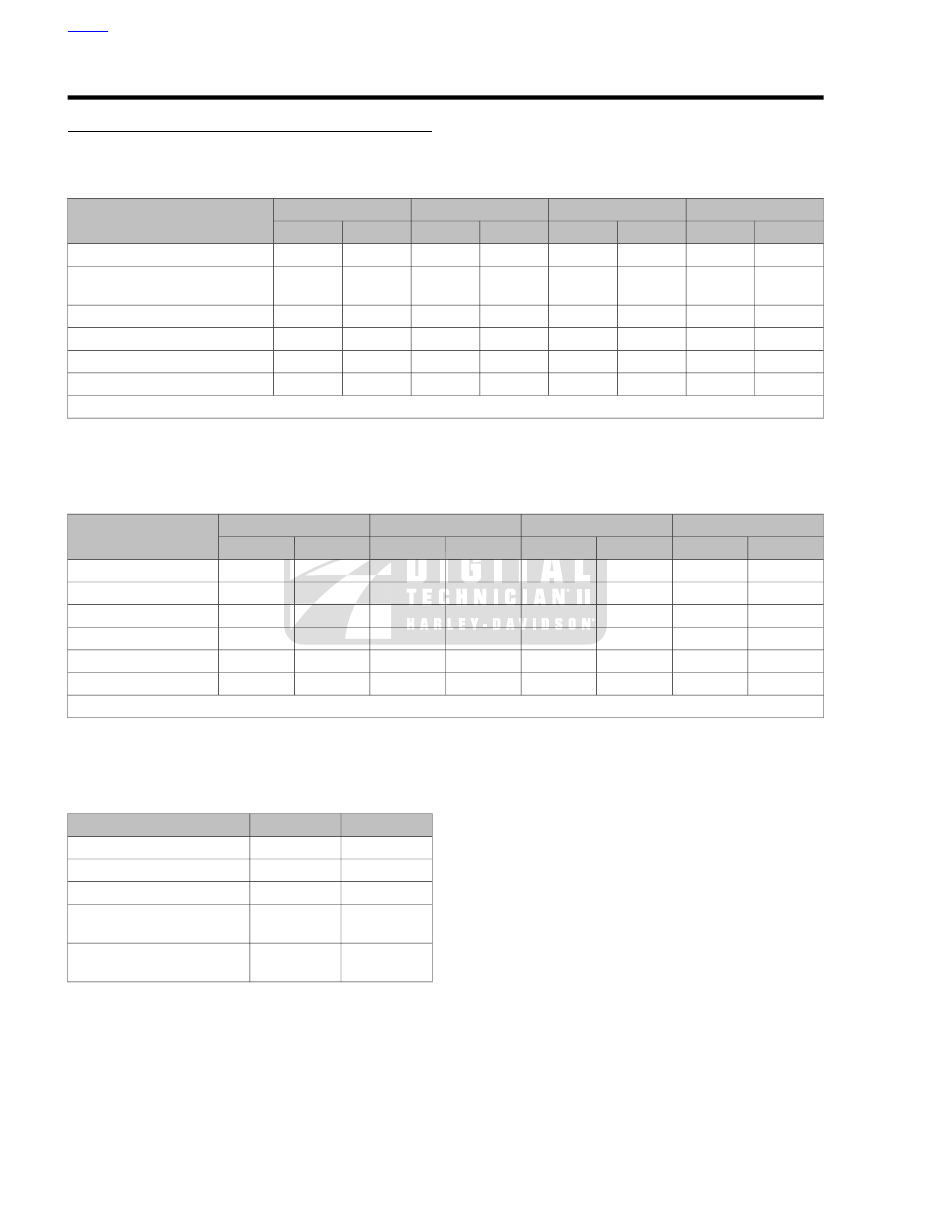
Table 2-1. Dimensions: FLHTC, FLHTCU, FLHTK, FLTRU

FLTRU

FLHTK

FLHTCU

FLHTC

ITEM

MM

IN.

MM

IN.

MM

IN.

MM

IN.

1613

63.5

1613

63.5

1613

63.5

1613

63.5

Wheel base

2507

98.7

2504

98.6

2504

98.6

2497

98.3

Overall length (Tour-Pak in rear-
most position)

919

36.2

965

38.0

965

38.0

965

38.0

Overall width

130

5.1

130

5.1

130

5.1

130

5.1

Road clearance

1397

55.0

1549

61.0

1549

61.0

1549

61.0

Overall height

693

27.3

693

27.3

693

27.3

693

27.3

Saddle height*

*With 180 lb. (81.7 kg) rider on seat

Table 2-2. Dimensions: FLHR, FLHRC, FLTRX, FLHX

FLHX

FLTRX

FLHRC

FLHR

ITEM

MM

IN.

MM

IN.

MM

IN.

MM

IN.

1613

63.5

1613

63.5

1613

63.5

1613

63.5

Wheel base

2413

95.0

2413

95.0

2393

94.2

2413

95.0

Overall length

965

38.0

909

35.8

953

37.5

950

37.4

Overall width

119

4.7

130

5.1

130

5.1

130

5.1

Road clearance

1326

52.2

1270

50.0

1400

55.1

1400

55.1

Overall height

663

26.1

663

26.1

678

26.7

673

26.5

Saddle height*

*With 180 lb. (81.7 kg) rider on seat

Table 2-3. Capacities

LITERS

U.S.

ITEM

22.71

6.00 gal

Fuel tank (total)

3.79

1.00 gal

Low fuel warning light on

3.79

4.00 qt.

Engine oil with filter

0.95

1.00 qt.

Transmission
(approximate)

1.32

1.40 qt.

Primary chaincase
(approximate)

HOME

2-6 2011 Touring Service: Chassis

Table 2-4. Weights: FLHTC, FLHTCU, FLHTK, FLTRU

FLTRU

FLHTK

FLHTCU

FLHTC

ITEM

KG

LB.

KG

LB.

KG

LB.

KG

LB.

385.6

850

388.7

857

386.5

852

375.1

827

Weight as shipped from
factory

616.9

1360

616.9

1360

616.9

1360

616.9

1360

GVWR

226.8

500

226.8

500

226.8

500

226.8

500

GAWR front

420.5

927

420.5

927

420.5

927

420.5

927

GAWR rear

Table 2-5. Weights: FLHR, FLHRC, FLTRX, FLHX

FLHX

FLTRX

FLHRC

FLHR

ITEM

KG

LB.

KG

LB.

KG

LB.

KG

LB.

356.1

785

350.2

772

350.6

773

351.5

775

Weight as shipped from
factory

616.9

1360

616.9

1360

616.9

1360

616.9

1360

GVWR

226.8

500

226.8

500

226.8

500

226.8

500

GAWR front

420.5

927

420.5

927

420.5

927

420.5

927

GAWR rear

NOTES

Gross vehicle weight rating (GVWR) (maximum allowable
loaded vehicle weight) and corresponding gross axle
weight rating (GAWR) are given on a label located on the
frame steering head.

For important information regarding tire data and tire
inflation, see

1.8 TIRES AND WHEELS

.

Tire Specifications

Use only Harley-Davidson approved tires. See a Harley-
Davidson dealer. Using non-approved tires can adversely
affect stability, which could result in death or serious
injury. (00024a)

Tire sizes are molded on the sidewall. Refer to the tire fitment
tables below. Rim size and contour are cast or stamped into
the exterior surface of the rim.

Example: T19 x 2.15 MT DOT. "T" indicates that the rim con-
forms to Tire and Rim Association standards. The "19" is the
normal diameter of the rim in inches, measured at the bead
seat diameter. The "2.15" is the width of the bead seat meas-
ured in inches. "MT" designates the rim contour. "DOT" means
that the rim meets Department of Transportation Federal Motor
Vehicle Safety Standards.

Table 2-6. Tire Fitment - Tubeless Cast Wheels

APPROVED TIRE

RIM VALVE

HOLE DIA.

RIM SIZE AND

CONTOUR

WHEEL SIZE

AND POSITION

Dunlop D408F

0.45 in. (11.4 mm)

T18 x 3.50 MT

18 in. - Front

130/70B18 63H

Dunlop D408F

0.45 in. (11.4 mm)

T17 x 3.00 MT

17 in. - Front

130/80B17 65H

Dunlop D407

0.45 in. (11.4 mm)

T16 x 5.00 MT

16 in. - Rear

180/65B16 81H

HOME

2011 Touring Service: Chassis 2-7

Table 2-7. Tire Fitment - Tube Type Steel Laced Wheels

APPROVED

TIRE

TUBE

SIZE

RIM SIZE &

CONTOUR

WHEEL SIZE

& POSITION

Dunlop D408F

MT90-16/MU85-16

T16 x 3.00D

16 in - Front

130/90-B16 67H

130/90-150/80-16

Dunlop D407

180/65-16

T16 x 5.00 MT

16 in - Rear

180/65-16 81H

Table 2-8. Tire Fitment - Tube Type Chrome Aluminum Profile Laced Wheels

APPROVED

TIRE

TUBE

SIZE

RIM SIZE &

CONTOUR

WHEEL SIZE

& POSITION

Dunlop D408F

MT90-16/MU85-16

T16 x 3.00 MT

16 in - Front

130/90B16 67H

130/90-150/80-16

Dunlop D408F

130/80-17

T17 x 3.00 MT

17 in - Front

130/80-B17 65H

Dunlop D407

180/65-16

T16 x 5.00 MT

16 in - Rear

180/65-16 81H

Table 2-9. Tires

PRESSURE (COLD)

APPROVED TIRE

SIZE

MOUNT

MODEL

kPa

PSI

248

36

Dunlop D408F 130/80B17 65H

17 in.

front

All models except FLHRC,
FLTRX, FLHX

248

36

Dunlop D408F 130/90B16 67H

16 in.

front

FLHRC

248

36

Dunlop D408F 130/70B18 63H

18 in.

front

FLTRX, FLHX

276

40

Dunlop D407 180/65B16

16 in.

rear

All models

HOME

2-8 2011 Touring Service: Chassis

2.3

VEHICLE IDENTIFICATION NUMBER (V.I.N.)

VEHICLE IDENTIFICATION NUMBER:
TOURING MODELS

The full 17-digit serial or Vehicle Identification Number (V.I.N.)
is stamped on the right frame down tube below the steering
head. A label bearing the V.I.N. code is also affixed on the right
side of the motorcycle on the front downtube.

An abbreviated V.I.N. (Motor Identification Number) is stamped
on the left side crankcase at the cylinder base.

NOTE

Always give the full 17-digit Vehicle Identification Number when
ordering parts or making any inquiry about your motorcycle.

1 HD 1 KE M A 9 B B 600041

1

2

3

4

5

6

7

8

9

10

om00883

Figure 2-1. Typical Harley-Davidson V.I.N.: 2011 Touring Models

Table 2-10. Harley-Davidson V.I.N. Breakdown: 2011 Touring Models

POSSIBLE VALUES

DESCRIPTION

POSITION

1=Originally manufactured for sale

within

the United States

Market designation

1

5=Originally manufactured for sale

outside

of the United States

HD=Harley-Davidson motorcycle

Manufacturer/vehicle type

2

1=Heavyweight motorcycle (901 cc or larger)

Motorcycle type

3

See V.I.N. model code table

Model

4

4=Twin Cam 96

, 1584 cc air-cooled, fuel-injected

Engine type

5

M=Twin Cam 103

, 1690 cc air-cooled, fuel-injected

Mid-year or Special Introduction

Normal Introduction

Introduction date/calibration

6

2, 4=Domestic

1=Domestic

5, 6=California

3=California

B=Canada

A=Canada

D=HDI

C=HDI

F=Japan

E=Japan

H=Australia

G=Australia

K=Brazil

J=Brazil

M=Asia Pacific

L=Asia Pacific

P=India

N=India

Can be 0-9 or X

V.I.N. check digit

7

B=2011

Model year

8

B=York, PA U.S.A.

Assembly plant

9

Varies

Sequential number

10

HOME

2011 Touring Service: Chassis 2-9

Table 2-11. V.I.N. Model Codes: 2011 Touring Models

MODEL

CODE

MODEL

CODE

FLHX Street Glide

®

KB

FLHR Road King

®

FB

FLHTK Electra Glide

®

Ultra Limited

KE

FLHRC Road King

®

Classic

FR

FLHTC Electra Glide

®

Classic

FF

FLHR Road King

®

Shrine

FW

FLHTCU Ultra Classic

®

ElectraGlide

®

FC

FLTRX Road Glide

®

Custom

KH

FLHTCU Ultra Classic

®

Electra Glide

®

Shrine

FL

FLTRU Road Glide

®

Ultra

KG

HOME

2-10 2011 Touring Service: Chassis

2.4

FRONT WHEEL

REMOVAL

When lifting a motorcycle using a jack, be sure jack con-
tacts both lower frame tubes where down tubes and lower
frame tubes converge. Never lift by jacking on cross-
members, oil pan or other housings. Failure to comply can
cause serious damage resulting in the need to perform
major repair work. (00586c)

1.

Raise the wheel with a suitable lifting device.

2.

Inspect the wheel bearings. See

2.10 SEALED WHEEL

BEARINGS

.

3.

If present, cut cable straps to release front wheel speed
sensor cable and front fender tip lamp wires from left cal-
iper brake hose.

4.

See

Figure 2-2

. Remove two brake caliper mounting

fasteners (1). Slide brake caliper straight down to remove
from brake disc. Secure caliper to rail of engine guard
using a cable strap.

5.

If necessary, remove retainer (2) to release wheel speed
sensor harness from bracket.

6.

Remove right side brake caliper.

NOTE

Do not operate the front brake hand lever with the front wheel
removed or the caliper pistons may be forced out. The caliper
contains no serviceable components and would require
replacement.

7.

See

Figure 2-3

. Hold the axle stationary with a screwdriver

or steel rod through hole in axle (10) on right side and
remove the axle nut (1) and flat washer (2).

8.

Loosen the two axle holder nuts at bottom of right side
fork slider.

1

2

sm05733

1. Caliper fasteners
2. Wheel speed sensor cable retainer

Figure 2-2. Remove Front Caliper

9.

Remove the axle from right side of motorcycle. Catch
external spacer(s) and front wheel speed sensor (if ABS
equipped) as the axle is removed.

NOTE

If ABS equipped, never pull wheel speed sensor cable taut or
use to retain wheel, axle or other components. Always keep
wheel speed sensor and ABS encoder bearing away from
magnetic fields such as magnetic parts trays, magnetic base
dial indicators, alternator rotors, etc. or damage will occur.

10. If necessary, remove five screws (12) to release brake

discs from hub.

HOME

2011 Touring Service: Chassis 2-11

17

15

16

6

7

8

2

1

3

4

13

5

11

14

9

4

13

3

10

12

sm05874

10.

1.

Axle

Axle nut

2.

11.

Flat washer

Brake disc (left side)

12.

3.

Screw (10)

External spacer

4.

13.

Standard bearing

Brake disc (right side)

14.

5.

Laced wheel, chrome

ABS encoder bearing

6.

15.

Front wheel speed sensor

Cast wheel

16.

7.

Slotted cast wheel

Cable clip

8.

17.

Clip bracket

Laced wheel, profile

9. Spacer sleeve

Figure 2-3. Front Wheel (Exploded View)

CLEANING AND INSPECTION

1.

Thoroughly clean all parts in solvent (wheel speed sensor
and bearings excepted) and inspect for damage or
excessive wear.

2.

Replace brake discs if warped or badly scored. Measure
disc thickness for excessive wear. Minimum acceptable
thickness is stamped on side of disc.

INSTALLATION

NOTE

When installing front brake discs, align the rivets with the rivets
on the opposite disc.

HOME

2-12 2011 Touring Service: Chassis

Do not re-use brake disc/rotor screws. Re-using these
screws can result in torque loss and damage to brake
components. (00319c)

1.

See

Figure 2-3

. If removed, install brake discs using

new

screws (12). Tighten screws in a crosswise pattern to 16-
24 ft-lbs (21.7-32.5 Nm).

2.

Place wheel into position between fork sliders with the
valve stem on the right side of the motorcycle.

3.

Apply a light coat of SILVER GRADE ANTI-SEIZE (Part
No. 98960-97) to axle, bearing bores and bore of spacer
sleeve.

4.

Slide axle through right fork slider and external spacer into
wheel hub.

NOTE

Be sure that grooves on external spacer(s), or index pin on
front wheel speed sensor (if ABS equipped), are on the out-
board side. If motorcycle is not ABS equipped, external spacers
on left and right side of wheel hub are interchangeable.

5.

Push axle through front wheel speed sensor (if ABS
equipped) or second external spacer, and left fork slider.

6.

Install flat washer and axle nut.

7.

See

Figure 2-4

If ABS equipped, rotate front wheel speed

sensor in a counter-clockwise direction until index pin
makes contact with shoulder on left fork slider.

8.

Hold axle stationary and tighten axle nut to 60-65 ft-lbs
(81.4-88.1 Nm).

NOTE

When securing the axle holder, equally tighten the nuts so the
gaps, front and rear, are approximately the same.

9.

Push and hold right fork slider inboard until it contacts
external spacer and equally tighten axle holder nuts to
132-180

in-lbs

(14.9-20.3 Nm).

NOTE

See

Figure 2-3

If removed, secure wheel speed sensor cable

in bracket (8). Be sure that tab (stamped ABS) on clip is
installed in slot of bracket from inboard side. Clip cannot be
installed once mounting fasteners are started.

10. Install left side brake caliper and sensor cable retainer (if

equipped). See

2.13 FRONT BRAKE CALIPER

.

After servicing brakes and before moving motorcycle,
pump brakes to build brake system pressure. Insufficient
pressure can adversely affect brake performance, which
could result in death or serious injury. (00279a)

11. Operate front brake hand lever several times to set brake

pads to proper operating position.

12. If ABS equipped, install three

new

cable straps as follows:

a.

On the brake hose lower crimp capturing front wheel
speed sensor cable and brake hose.

b.

Approximately midway between the upper and lower
brake hose crimps capturing front wheel speed sensor
cable, brake hose and front fender tip lamp wires, if
equipped.

c.

Approximatels 2.5 in. (63.5 mm) below the brake hose
upper crimp capturing front wheel speed sensor cable,
brake hose and front fender tip lamp wires, if
equipped.

sm04027

Figure 2-4. Front Wheel Speed Sensor Index Pin (ABS

Equipped)

HOME

2011 Touring Service: Chassis 2-13

2.5

REAR WHEEL

REMOVAL

TOOL NAME

PART NUMBER

AXLE NUT TORQUE ADAPTER

HD-47925

1.

Remove saddlebags. See

2.26 SADDLEBAGS

.

When lifting a motorcycle using a jack, be sure jack con-
tacts both lower frame tubes where down tubes and lower
frame tubes converge. Never lift by jacking on cross-
members, oil pan or other housings. Failure to comply can
cause serious damage resulting in the need to perform
major repair work. (00586c)

2.

Raise the wheel with a suitable lifting device.

3.

Inspect wheel bearings. See

2.10 SEALED WHEEL

BEARINGS

.

4.

Remove left side muffler. See

4.19 EXHAUST SYSTEM

.

5.

On models equipped with low profile shock absorbers
(FLHX, FLTRX), remove left side lower saddlebag support
rail. See

2.27 SADDLEBAG SERVICE, Saddlebag

Guard/Support Rail

.

6.

ABS equipped:

Cut cable strap to release rear wheel

speed sensor cable from rear brake hose.

7.

Remove rear brake caliper but do not disconnect the brake
hose. Set brake caliper on passenger footboard. See

2.15 REAR BRAKE CALIPER

.

NOTE

Do not operate the rear brake pedal with the caliper removed
or the caliper pistons may be forced out. The caliper contains
no serviceable components and would require replacement.

8.

See

Figure 2-5

. Remove E-clip (1) from the groove at the

end of the axle.

9.

See

Figure 2-6

. Hold weld nut on left side and loosen cone

nut using AXLE NUT TORQUE ADAPTER (Part No. HD-
47925).

10. Remove cone nut and adjuster cam from axle.

11. Rotate weld nut on opposite side of axle counterclockwise

until wheel is loose.

NOTE

If ABS equipped, never pull wheel speed sensor cable taut or
use to retain wheel, axle or other components. Always keep
wheel speed sensor and ABS encoder bearing away from
magnetic fields such as magnetic parts trays, magnetic base
dial indicators, alternator rotors, etc. or damage will occur.

12. Remove the axle from the left side of the motorcycle. Catch

external spacer(s), caliper bracket, and rear wheel speed
sensor (if ABS equipped) as the axle is removed.

13. Remove caliper bracket from anchor weldment on rear

fork.

NOTE

To protect belt on vehicles with a hot exhaust, place a shop
towel over exhaust crossover.

14. Move wheel forward and slip belt off compensator

sprocket.

NOTE

Hold sprocket while removing rear wheel. Sprocket may drop
from wheel if isolators are excessively worn.

15. If necessary, remove brake disc from hub. If wheel is to

be assembled with the same disc, mark both the wheel
and disc, so that it can be installed in its original position.

HOME

2-14 2011 Touring Service: Chassis

18

5

8

20

19

7

12

13

5

4

3

2

1

9

16

14

17

16

10

11

6

sm05743

11.

1.

Axle

E-clip

2.

12.

Cone nut

Brake disc

13.

3.

Screw (5)

Adjuster cam

4.

14.

External spacer (thick)

Spacer, compensator

15.

5.

Isolator

Standard bearing

6.

16.

ABS encoder bearing

Compensator sprocket

17.

7.

Sprocket bearing (2)

Rear wheel speed sensor

8.

18.

Laced wheel, chrome

Cast wheel

19.

9.

Slotted cast wheel

Spacer sleeve

10.

20.

External spacer (thin)

Laced wheel, profile

Figure 2-5. Rear Wheel (Exploded View)

CLEANING AND INSPECTION

1.

Thoroughly clean all parts in solvent (wheel speed sensor
and bearings excepted) and inspect for damage or
excessive wear.

2.

Replace brake disc if warped or badly scored. Measure
disc thickness for excessive wear. Minimum acceptable
thickness is stamped on side of disc.

3.

Check the compensator sprocket for wear, tooth damage,
cracks or pitting. Check isolator for crumbling, flaking,
excessive wear or general deterioration. Replace parts as
necessary.

HOME

2011 Touring Service: Chassis 2-15

INSTALLATION

TOOL NAME

PART NUMBER

BELT TENSION GAUGE

HD-35381A

NOTE

Always install brake disc in its original position.

Do not re-use brake disc/rotor screws. Re-using these
screws can result in torque loss and damage to brake
components. (00319c)

1.

If removed, install brake disc in its original position using

new

screws. Tighten screws in a crosswise pattern to 30-

45 ft-lbs (41-61 Nm).

2.

Verify that sprocket is square and fully seated in bowl area
of wheel.

3.

Place wheel in rear fork. Install belt over sprocket and
slide the wheel back.

Never bend belt forward into a loop smaller than the drive
sprocket diameter. Never bend belt into a reverse loop.
Over bending can damage belt resulting in premature
failure, which could cause loss of control and death or
serious injury. (00339a)

4.

Seat the caliper bracket on the anchor weldment of the
rear fork.

5.

Apply a light coat of SILVER GRADE ANTI-SEIZE (Part
No. 98960-97) to axle, bearing bores and bore of spacer
sleeve.

6.

Slide axle through left side of rear fork, external spacer
(thin), sprocket and into wheel hub.

NOTE

Be sure that grooves on external spacer, or index pin on rear
wheel speed sensor (if ABS equipped), are on the outboard
side.

7.

Push axle through rear wheel speed sensor (if ABS
equipped) or external spacer (thick), caliper bracket, and
right side of rear fork.

8.

Rotate axle so that the flat on the threaded end is topside.
With the cam forward, install adjuster cam on the end of
the axle.

9.

Apply a light coat of SILVER GRADE ANTI-SEIZE (Part
No. 98960-97) to the inboard side of the cone nut avoiding
contact with threads. Install cone nut on axle. Finger
tighten only.

2

1

sm04528

1. Torque wrench
2. Axle nut torque adapter (HD-47925)

Figure 2-6. Install Tool Perpendicular to Torque Wrench

10.

ABS equipped:

route sensor cable forward and outboard

of caliper bracket. Continue forward following the top of
the rear fork. Rotate rear wheel speed sensor in a counter-
clockwise direction until index pin makes contact with
caliper bracket at point shown in

Figure 2-7

.

11. Tighten the cone nut to a preliminary torque of 15-20 ft-

lbs (20-27 Nm). The final torque will be done during the
belt adjustment procedure.

12. Install the brake caliper and tighten screws to 43-48 ft-lbs

(58.3-65.1 Nm).

13. Secure rear wheel speed sensor cable to the brake hose

with the conduit clip located approximately 1.25 in. (31.8
mm) in front of the brake hose crimp.

14. Adjust drive belt using BELT TENSION GAUGE (Part

No.

HD-35381A).

See

1.12

DRIVE

BELT

AND

SPROCKETS

.

15. Install a

new

E-clip with the flat side out in groove on right

side of axle.

16. On models equipped with low profile shock absorbers,

install the left side lower saddlebag support rail. See

2.27 SADDLEBAG SERVICE, Saddlebag Guard/Support
Rail

.

HOME

2-16 2011 Touring Service: Chassis

sm04028

Figure 2-7. Rear Wheel Speed Sensor Index Pin (ABS

Equipped)

17. Install the left side muffler. See

4.19 EXHAUST SYSTEM

.

After servicing brakes and before moving motorcycle,
pump brakes to build brake system pressure. Insufficient
pressure can adversely affect brake performance, which
could result in death or serious injury. (00279a)

18. Operate the rear brake pedal several times to set brake

pads to the proper operating position.

19. Install saddlebags. See

2.26 SADDLEBAGS

.

HOME

2011 Touring Service: Chassis 2-17

2.6

REAR WHEEL COMPENSATOR

ISOLATOR REPLACEMENT

Removal

1.

Remove rear wheel. See

2.5 REAR WHEEL

.

2.

Pull sprocket from wheel.

3.

Remove isolator from wheel.

Installation

1.

See

Figure 2-8

. Lubricate each segment (2) of

new

isolator

with 50/50 mix of isopropyl alcohol and water. Do not use
a petroleum based lubricant.

2.

Push isolator into wheel. Verify that each isolator segment
bottoms in bowl area of wheel and that each segment is
flush against side walls of rib (1).

3.

Using a 50/50 mix of isopropyl alcohol and water, lubricate
sides of each isolator segment sprocket lug gaps (3).

4.

Aligning lugs on sprocket with gaps between isolator
segments, push sprocket onto wheel.

5.

Install rear wheel. See

2.5 REAR WHEEL

.

2

1

3

sm05781

1. Rib
2. Isolator segment
3. Sprocket lug gap

Figure 2-8. Install Isolator in Wheel

SPROCKET BEARING REPLACEMENT

TOOL NAME

PART NUMBER

REAR WHEEL COMPENSATOR
SPROCKET BEARING
REMOVER/INSTALLER

HD-48921

Removal

1.

Remove the rear wheel. See

2.5 REAR WHEEL

.

2.

Pull the sprocket from the wheel.

3.

See

Figure 2-9

and upper frame of

Figure 2-10

. Support

the base (1) of REAR WHEEL COMPENSATOR
SPROCKET BEARING REMOVER/INSTALLER (Part
No. HD-48921) on a press with the large OD topside and
the long pin (3) down.

4.

Slide sleeve (2) over the short pin.

5.

See lower frame of

Figure 2-10

. With the inboard side

facing up, slide the sprocket over the sleeve until it rests
on the base.

6.

Slide the small OD of driver (6) over the sleeve until it
contacts spacer (5).

7.

Apply pressure to the driver until bearings drop into base.
Disassemble the tool and discard the bearings.

Installation

1.

See upper frame of

Figure 2-10

. Support the base (1) of

REAR WHEEL COMPENSATOR SPROCKET BEARING
REMOVER/INSTALLER (Part No. HD-48921) on the deck
of an arbor press with the large OD topside and long pin
(3) down.

2.

Slide sleeve (2) over the short pin.

3.

Verify that the sprocket bearing bore is clean and dry.

4.

See upper frame of

Figure 2-11

. With the outboard side

facing up, slide the sprocket over the sleeve until it rests
on the base.

5.

Place spacer (1) in the sprocket with the small diameter
facing down.

6.

Set bearing in place.

7.

See lower frame of

Figure 2-11

Center the large OD of

driver (3) on the bearing. Verify the driver contacts the
outer bearing race (4) all the way around.

8.

Apply pressure to the driver until the bearing makes firm
contact with the counterbore in the sprocket.

9.

Repeat with the second bearing.

10. Using a 50/50 mix of isopropyl alcohol and water, lubricate

the sides of each isolator segment where contact occurs
with the sprocket lugs.

11. Install the sprocket onto wheel.

12. Install rear wheel. See

2.5 REAR WHEEL

.

HOME

2-18 2011 Touring Service: Chassis

1

2

3

sm04547

1. Base
2. Sleeve
3. Driver

Figure 2-9. Rear Wheel Compensator Bearing

Remover/Installer (HD-48921)

2

1

6

4

5

3

sm05773

1. Base
2. Sleeve
3. Long pin
4. Sprocket (inboard side up)
5. Spacer
6. Driver

Figure 2-10. Remove Compensator Sprocket Bearing

HOME

2011 Touring Service: Chassis 2-19

3

2

4

1

sm05774

1. Spacer
2. Sprocket (outboard side up)
3. Driver
4. Bearing outer race

Figure 2-11. Install Compensator Sprocket Bearing

HOME

2-20 2011 Touring Service: Chassis

2.7

WHEEL LACING: FRONT RIM

WHEEL LACING: ANGLE FLANGE HUB

NOTES

See

Figure 2-12

The following procedure is valid for 40-

spoke wheels that use an angle flange hub regardless of
rim style or diameter.

The primary brake side of the hub can be identified as
having one or two grooves cut into the disc mounting sur-
face.

1

2

sm06505

1. Outer spoke hole
2. Inner spoke hole

Figure 2-12. Angle Flange Hub

1.

Place hub on workbench:

a.

Front: primary brake side up.

b.

Rear: brake side down.

2.

Lubricate all spoke threads and nipple shoulders with tire
mounting lubricant.

3.

Install all spokes in the lower flange.

4.

See

Figure 2-13

. Flip hub over. Gather all outer spokes

and hold upright with a rubber band. Repeat with the inner
spokes using a second rubber band.

5.

Install spokes in remaining flange.

6.

Rotate the lower flange spokes as far as they will go:

a.

Outer spokes clockwise.

b.

Inner spokes counterclockwise.

7.

Center the rim over the hub and spokes assembly and
support on wooden blocks approximately 1.5 in (38.1 mm)
thick.

a.

If valve is not located in the center of the rim, place
valve hole facing up.

b.

19 in. and 21 in. with the valve located in the center
of the rim can be placed either side up.

NOTE

Install nipples until approximately 1/8 in (3.2 mm) of spoke
thread shows.

1

2

sm06503

1. Outer spoke
2. Inner spoke

Figure 2-13. Spokes Gathered

8.

Install lower flange outer spokes and loosely install spoke
nipples:

See

Figure 2-14

. Rim with side valve hole: start at the

valve stem hole (1).

See

Figure 2-15

. Rim with center valve hole: start at the

first hole counterclockwise (1) from valve stem hole.

9.

Install remaining outer spokes in every 4th hole.

10. Install lower flange inner spokes and loosely install spoke

nipples:

a.

Starting at the 2nd hole counterclockwise (2) from
first spoke installed, install inner spoke.

b.

Install remaining inner spokes in every 4th hole.

11. Carefully release upper flange inner spokes and fan out

around rim, rotating them clockwise.

12. Starting at the first hole counterclockwise (3) from first

spoke installed, install inner spoke. Install all remaining
inner spokes in every 4th hole.

13. Carefully release upper flange outer spokes and fan out

around rim, rotating them counterclockwise.

14. Install outer spokes in remaining holes (4).

15. Verify spoke heads are seated. Evenly hand-tighten spoke

nipples until snug. Only tighten until slack is removed.
Proper torque will be applied when the wheel is trued.
Adjust offset and true the wheel. See

2.9 CHECKING AND

TRUING WHEELS

.

HOME

2011 Touring Service: Chassis 2-21


Content      ..     9      10      11      12     ..