Harley Davidson 2011 Touring Models. Service Manual - page 12
 

  Главная      Harley Davidson     Harley Davidson 2011 Touring Models. Service Manual


Search            copyright infringement  


Content      ..     10      11      12      13     ..


Harley Davidson 2011 Touring Models. Service Manual - page 12


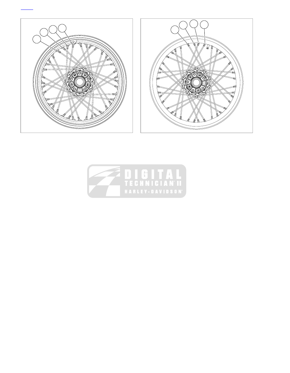
1

3

2

4

sm06506

Figure 2-14. Side Valve Rim

1

3

2

4

sm06507

Figure 2-15. Center Valve Rim

HOME

2-22 2011 Touring Service: Chassis

2.8

WHEEL LACING: 16 INCH REAR RIM

WHEEL LACING: 16 IN. REAR WHEEL

1.

See

Figure 2-16

. Divide spokes into two groups.

a.

Outer spokes (short heads) (1).

b.

Inner spokes (long heads) (2).

NOTE

See

Figure 2-17

. The spoke holes in the wheel hub are

staggered, alternating between inner holes (2) (nearer hub
center) and outer holes (1) (nearer hub edge).

1

2

sm06086

1. Short head (outer spoke)
2. Long head (inner spoke)

Figure 2-16. Spoke Heads

2

1

sm01786

1. Outer spoke hole
2. Inner spoke hole

Figure 2-17. Spoke Hole Pattern

2.

Lubricate all spoke threads and nipple shoulders with tire
mounting lubricant.

3.

See

Figure 2-18

Place hub on bench with the brake disc

side down. Insert outer spokes (1) (short-head) into the
outer holes and inner spokes (2) (long-head) in the inner
holes.

4.

See

Figure 2-19

. After spokes are installed, flip wheel hub

over. Swing outer spokes counterclockwise and inner
spokes clockwise as shown. Each inner spoke should
cross four outer spokes, and each outer spoke should
cross four inner spokes.

5.

Install all outer spokes, then all inner spokes on brake-
side flange. Swing inner spokes counterclockwise and
outer spokes clockwise on brake-side flange, each
crossing four of the opposite type.

1

2

sm06031

1. Outer spoke (short head)
2. Inner spoke (long head)

Figure 2-18. Lacing Wheel Hub

sm06032

Figure 2-19. Arrange Spokes

NOTE

See

Figure 2-20

. Tape placed across brake disc flange and

spoke heads will hold spokes up away from lower row of
spokes, making it easier to gather upper spokes.

6.

See

Figure 2-20

. Group upper spokes (brake-side) into

bundles of two as shown. Join an outer spoke (1) with the
inner spoke (2) that is located four places clockwise and

HOME

2011 Touring Service: Chassis 2-23

secure with tape (3) approximately 1 in. (25 mm) from
threaded end.

1

2

3

4

3

1

2

sm06033

1. Outer spoke (short head)
2. Inner spoke (long head)
3. Tape

Figure 2-20. Bundling Spokes

7.

Make sure all spokes on compensator-side flange are still
arranged properly and pointing in the correct direction:

a.

All outer spokes (short-head) point counterclockwise,
crossing four inner spokes.

b.

All inner spokes (long-head) point clockwise, crossing
four outer spokes (short-head).

c.

Angle all spokes as far as they will go without overlap-
ping the next LIKE spoke.

NOTES

Verify all inner spokes lay inboard and outer spokes lay
outboard.

See

Figure 2-21

The valve stem hole location (1) is

centered on the rim so rim orientation is not important.

8.

See

Figure 2-21

Center the rim over the hub/spoke

assembly and support on wooden blocks (2) approximately
1.5 in (38.1 mm) thick. Rotate so valve stem hole (1) is
near a pair of taped spokes.

1

2

2

3

sm06034

1. Valve stem location
2. Wooden blocks
3. Beginning spoke location

Figure 2-21. Place Rim

NOTE

See

Figure 2-22

It is recommended that the first spoke be

installed near the valve stem hole (5). Place spoke nipples
through several rim holes to determine the hole direction. Only
one spoke will fit into the spoke nipple correctly. When con-
necting the spoke to the spoke nipple, finger tighten two to
three threads.

9.

See

Figure 2-22

. Begin with the outer spokes (short-head)

of the lower (compensator) flange. Using the spoke align-
ment method discussed previously, locate a spoke hole
(1) just left of the valve stem hole (5) that points toward
an outer spoke.

a.

Secure spoke to nipple. Skip three rim holes and
repeat with the next outer spoke. Follow pattern to
complete lower (compensator) flange outer spokes
(short-head).

b.

Once completed, check for three empty holes between
each spoke.

10. Install the lower (compensator) flange inner spokes (long-

head) next. Choose a beginning spoke (2) near the valve
stem hole (5).

a.

Each inner spoke (long-head) points clockwise and
crosses four outer spokes (short-head).

b.

Secure spoke to nipple. Complete installing lower
flange inner spokes (long-head).

HOME

2-24 2011 Touring Service: Chassis

3

1

5

4

2

3

1

4

2

5

sm06010

1. Compensator-side outer spoke
2. Compensator-side inner spoke
3. Brake-side inner spoke
4. Brake-side outer spoke
5. Valve stem hole

Figure 2-22. Begin Lacing

NOTE

Use care not to move outer spokes (short-head) under inner
spokes (long-head) when removing the tape or they will become
trapped underneath the inner row of spokes.

11. See

Figure 2-21

Remove tape from each upper bundle

and fan the spokes out toward the rim.

NOTE

All upper flange inner spokes (long-head) should point counter-
clockwise and outer spokes (long-head) clockwise.

12. See

Figure 2-22

Choose a beginning spoke near the valve

stem hole (5). Start with a top flange inner spoke (3) (long-
head) first.

a.

Secure spoke to nipple. Follow pattern to complete
upper (brake-side) flange inner spokes (long-head).

b.

Once completed, check for one empty hole after every
third spoke.

13. Install upper flange outer spoke (4) (short-head).

14. Secure spoke to nipple. Complete upper flange outer

spokes (short-head).

sm06011

Figure 2-23. Completed 16 Inch Rear Wheel

15. Verify that completed wheel resembles

Figure 2-23

.

16. Verify spoke heads are seated. Evenly hand-tighten spoke

nipples until snug. Only tighten until slack is removed.
Proper torque will be applied when the wheel is trued.
Adjust offset and true the wheel. See

2.9 CHECKING AND

TRUING WHEELS

.

HOME

2011 Touring Service: Chassis 2-25

2.9

CHECKING AND TRUING WHEELS

GENERAL

Wheels should be checked for lateral and radial runout before
installing a

new

tire or tube. Checking cast or laced wheels is

performed using the same procedure.

Laced wheels having excess runout can be trued however,
cast wheels must be replaced. Never attempt to straighten cast
wheels.

Always check condition of the wheel bearings before checking
or adjusting wheel runout. See

1.8 TIRES AND WHEELS,

Wheel Bearings

.

CHECKING WHEEL RUNOUT

TOOL NAME

PART NUMBER

WHEEL TRUING AND BALANCING
STAND

HD-99500-80

Checking Lateral Runout

See

Figure 2-24

. Mount wheel in WHEEL TRUING AND BAL-

ANCING STAND (Part No. HD-99500-80).

NOTE

To more accurately measure runout, use a dial indicator in
place of the gauge rod.

To check lateral runout, place a gauge rod near, or dial indicator
on the rim bead flange and measure distance at several loca-
tions. Lateral runout must not exceed 0.030 in (0.76 mm).

sm02465

Figure 2-24. Checking Lateral Runout

Checking Radial Runout

See

Figure 2-25

Adjust truing stand gauge to the rim's tire

bead safety hump. Rotate wheel and measure distance at
several locations. Runout must not exceed 0.030 in (0.76 mm).

3

4

1

2

sm03117

1. Wheel truing and balancing stand
2. Radial runout
3. Gauge rod
4. Bead safety hump

Figure 2-25. Checking Radial Runout

If either measurement is not within specification:

Cast wheel: Replace the wheel.

Laced wheel: Adjust spokes to true the wheel. See steps
in this section.

LACED WHEEL RIM OFFSET

TOOL NAME

PART NUMBER

SPOKE WRENCH

HD-94681-80

WHEEL TRUING STAND

HD-99500-80

1.

See

Figure 2-26

Place a piece of tape to mark the center

of each group of four spokes as shown. The groups should
be directly opposite one another and approximately 90
degrees apart. Using different colors of tape or numbering
each group is helpful.

HOME

2-26 2011 Touring Service: Chassis

2

1

4

3

sm01235

Figure 2-26. Marking Spoke Groups

2.

See

Figure 2-27

. Mount wheel in WHEEL TRUING

STAND (Part No. HD-99500-80) using truing arbor. Tighten
arbor nuts so hub will turn on its bearings.

NOTE

The primary brake disc side of the hub can be identified by
having one or two grooves cut into the disc mounting surface.

3.

Lay a straightedge across the primary brake disc mounting
surface of hub and one of the marked spoke groups.

4.

See

Figure 2-28

Measure the distance from the

straightedge to the location shown, based on rim design,
to determine distance A. Refer to

Table 2-12

.

NOTES

Always loosen the appropriate spokes before tightening
the other two. Reversing this procedure will cause the rim
to become out-of-round.

Tighten or loosen spokes one flat at a time and recheck
measurement.

Always work on groups that are opposite each other to
maintain radial runout.

5.

If the dimension is not correct, adjust the four spokes using
SPOKE WRENCH (Part No. HD-94681-80). For example,
If the measurement on the rim

right

side is

less

than it

should be,

loosen

the two spokes attached to the hub

right

side and

tighten

the two spokes attached to the hub

left

side. Turn all four spokes an equal number of turns

until offset dimension is correct.

6.

Repeat the previous step for all groups on the wheel.

7.

Once offset is verified, proceed to

2.9 CHECKING AND

TRUING WHEELS, Truing Laced Wheels

.

sm03223

Figure 2-27. Checking Wheel Hub Offset Dimension

(typical)

Table 2-12. Offset Dimensions

OFFSET (A)

Rim Size

Rim Type

MM.

IN.

Steel Laced (1)

39.4-39.9

1.551-1.571

16 x 3

Front

27.9-28.4

1.098-1.118

16 x 5

Rear

Chrome Aluminum Laced Profile (2)

32.19-32.69

1.267-1.287

16 x 3

Front

32.19-32.69

1.267-1.287

17 x 3

Front

21.1-21.6

0.831-0.850

16 x 5

Rear

HOME

2011 Touring Service: Chassis 2-27

1

2

sm04390

1. Steel rim
2. Chrome aluminum profile rim

Figure 2-28. Laced Wheel Hub Offset Dimensions

TRUING LACED WHEELS

TOOL NAME

PART NUMBER

SPOKE NIPPLE WRENCH

94681-80

SPOKE TORQUE WRENCH

HD-48985

WHEEL TRUING STAND

HD-99500-80

NOTES

To more accurately measure runout, a dial indicator can
be used in place of the gauge rod.

Radial truing should be performed before lateral truing.

Radial Runout

1.

See

Figure 2-29

With the wheel mounted in WHEEL

TRUING STAND (Part No. HD-99500-80), adjust the truing
stand gauge (3) near to the rim's tire bead safety hump
(4). If using a dial indicator, place the tip on the safety
bead hump.

2.

If working with a straight flange hub, seat each spoke head
in the hub flange using a flat nose punch and mallet.

NOTES

Always loosen the appropriate spokes, using SPOKE
NIPPLE WRENCH (Part No. 94681-80), before tightening
the other two. Reversing this procedure will cause the rim
to become out-of-round.

Tighten or loosen spoke, one flat at a time, and recheck
measurement. Small changes in the spokes can make
large changes in the runout.

Always work on groups that are opposite each other to
maintain radial runout.

3.

Spin the rim slowly and check distance (2). The rim should
be true within 0.030 in (0.76 mm).

a.

If the rim contacts the gauge on or near a marked
group of spokes, loosen the spokes in the group on
the opposite side of the rim. Then tighten the spokes
in the group where the rim makes contact an equal
number of turns.

b.

If the rim contacts the gauge between two marked
groups, loosen the spokes in both groups on the
opposite side of the rim. Then tighten the spoke
groups on the side of the rim that makes contact an
equal number of turns.

4.

When the wheel is centered and trued, start at the valve
stem hole and tighten any loose spoke nipples one turn
at a time until they are snug.

5.

Working alternately across the wheel, use SPOKE
TORQUE WRENCH (Part No. HD-48985) evenly tighten
all spokes to specification listed in

Table 2-13

.

6.

If working with a straight flange hub, verify each spoke
head is seated in the hub flange using a flat nose punch
and mallet.

7.

Verify radial runout is still within specification.

8.

After you have verified that radial runout is still within
specification, proceed to lateral runout.

Spokes that are too tight can draw nipples through the rim
or distort hub flanges. Spokes that are too loose can
continue to loosen when put in service. Either condition
can adversely affect stability and handling, which could
result in death or serious injury. (00286a)

HOME

2-28 2011 Touring Service: Chassis

3

4

1

2

sm03117

1. Wheel truing and balancing stand
2. Radial runout
3. Gauge rod
4. Bead safety hump

Figure 2-29. Checking Radial Runout

Table 2-13. Spoke Nipple Torque Specification

MINIMUM TORQUE

RIM TYPE

55

in-lbs

(6.2 Nm)

All

Lateral Runout

NOTE

To more accurately measure runout, a dial indicator can be
used in place of the gauge rod.

1.

See

Figure 2-30

With the wheel mounted in WHEEL

TRUING STAND (Part No. HD-99500-80), adjust the
gauge rod (3) near the rim bead flange.

2.

Rotate the rim slowly and check lateral runout (2). If runout
exceeds 0.030 in (0.76 mm), adjust spokes as follows.

NOTES

Always loosen the appropriate spokes before tightening
the other two. Reversing this procedure will cause the rim
to become out-of-round.

Tighten or loosen spoke, one flat at a time, and recheck
measurement. Small changes in the spokes can make
large changes in the runout.

3.

Again working in groups of four, loosen two spokes on the
tight side and tighten the two spokes on the loose side.

4.

Repeat with each group until wheel is within specification.

5.

Verify all spoke nipples are tightened to the specification.
Refer to

Table 2-13

.

6.

If the tire is removed from the rim, file or grind off ends of
spokes that protrude through the nipples to prevent
puncturing tube when tire is mounted.

NOTE

After installation of the front wheel, visually check that it is
approximately centered between the fork fender bosses.

3

1

2

sm03115

1. Wheel truing and balancing stand
2. Lateral runout
3. Gauge rod

Figure 2-30. Checking Lateral Runout

HOME

2011 Touring Service: Chassis 2-29

2.10

SEALED WHEEL BEARINGS

INSPECTION

1.

Turn the wheel through several rotations.

NOTE

If ABS equipped, keep magnetic base dial indicator as far away
from wheel speed sensor and ABS encoder bearing as pos-
sible, or damage will occur.

2.

Check end play as follows:

a.

See

Figure 2-31

Mount a magnetic base dial indicator

to the brake disc. Set the indicator contact point on
the end of the axle.

b.

Firmly push the wheel to one side and zero the dial
indicator gauge.

c.

Firmly pull the wheel back as far as it will go and note
the reading of the dial indicator.

d.

Repeat the procedure to verify the reading.

e.

Bearings pass end play inspection if the reading is
less than 0.002 in. (0.051 mm).

f.

Replace the bearings if end play exceeds specifica-
tion, or if there is drag, rough rotation, abnormal noise
or anything unusual.

sm02234

Figure 2-31. Wheel Bearing Inspection (Front Wheel

Shown)

REMOVAL

TOOL NAME

PART NUMBER

WHEEL BEARING
REMOVER/INSTALLER

HD-44060C

1.

Remove wheel. See

2.4 FRONT WHEEL

or

2.5 REAR

WHEEL

.

3

1

6

2

4

5

sm01685

1. Forcing screw
2. Nut
3. Washer
4. Bearing
5. Bridge
6. Collet with ball bearing inside

Figure 2-32. Wheel Bearing Removal Tool

2.

If servicing rear wheel, remove the sprocket.

NOTES

On front wheel, remove the primary brake disc side (left)
bearing first.

ABS equipped motorcycles use both a special encoder
bearing (greenish tan in color) on the primary brake disc
side and a standard bearing (black) on the opposite side.
Select (Part No. HD-44060-11) if the motorcycle is ABS
equipped, or (Part No. HD-44060-10) for non-ABS
equipped motorcycles.

3.

See

Figure 2-32

Sparingly apply graphite lubricant to

threads of forcing screw (1) of WHEEL BEARING
REMOVER/INSTALLER (Part No. HD-44060C).

4.

Install nut (2), washer (3) and bearing (4) on forcing screw.
Insert assembly through hole in bridge (5).

5.

Place steel ball inside collet and install collet at end of
forcing screw.

6.

Insert collet into bearing. Hold forcing screw (1) and turn
hex on collet (6) until lip makes firm contact with inside
edge of bearing.

7.

See

Figure 2-33

Turn hex nut (2) until bearing is free.

Discard bearing.

8.

See

Figure 2-34

Remove spacer sleeve (6) from hub.

9.

Repeat steps to remove remaining bearing from opposite
side of wheel.

HOME

2-30 2011 Touring Service: Chassis

2

1

sm01686

1. Forcing screw
2. Nut

Figure 2-33. Removing Bearing

4

1

6

2

3

6

4

5

3

5

4

5

sm04499

1. Front wheel
2. Rear wheel
3. Brake disc (primary)
4. ABS encoder bearing
5. Standard bearing
6. Spacer sleeve

Figure 2-34. Wheel Bearing Assemblies

INSTALLATION

TOOL NAME

PART NUMBER

WHEEL BEARING
REMOVER/INSTALLER

HD-44060C

NOTES

Keep ABS encoder bearings away from magnetic fields
(such as magnetic parts trays, magnetic base dial indic-
ators, alternator rotors, etc.) or damage will occur.

Always replace both bearings as a complete set.

1.

See

Figure 2-35

Sparingly apply graphite lubricant to

threads of threaded rod (1) of WHEEL BEARING
REMOVER/INSTALLER (Part No. HD-44060C).

NOTE

Install the primary brake disc side bearing first. ABS equipped
motorcycles use a special encoder bearing (greenish tan in
color) on the primary brake disc side and a standard bearing
(black) on the opposite side.

2.

Install support plate (2) onto rod (1) and slide rod through
hub from the side opposite the primary brake side.

HOME

2011 Touring Service: Chassis 2-31

NOTE

Bearing orientation is important.

3.

See

Figure 2-36

. Place the bearing on the rod.

a.

Standard bearing with the lettered side against
installer (5).

b.

ABS bearing with greenish tan side against installer
(5).

4.

Install 1 inch installer (Part No. HD-44060-8) (5), bearing
(4), flat washer (3) and nut (2) onto rod.

5.

Hold hex on rod and turn nut (2) until bearing is fully
seated.

6.

Install spacer sleeve in hub.

7.

Reverse tool and install opposite side bearing until bearing
contacts spacer sleeve.

8.

Install wheel. See

2.4 FRONT WHEEL

or

2.5 REAR

WHEEL

.

1

2

sm01783

1. Threaded rod
2. Support plate

Figure 2-35. Assembling Installation Tool

4

5

6

1

2

3

sm01688

1. Threaded rod
2. Nut
3. Washer
4. Bearing
5. Installer
6. Wheel bearing

Figure 2-36. Installing Bearing

HOME

2-32 2011 Touring Service: Chassis

2.11

TIRES

GENERAL

Use only Harley-Davidson approved tires. See a Harley-
Davidson dealer. Using non-approved tires can adversely
affect stability, which could result in death or serious
injury. (00024a)

Be sure tires are properly inflated, balanced and have
adequate tread. Inspect your tires regularly and see a
Harley-Davidson dealer for replacements. Riding with
excessively worn, unbalanced or under-inflated tires can
adversely affect stability and handling, which could result
in death or serious injury. (00014a)

NOTES

Check runout on all cast or spoke wheels before installing
new tire. See

1.8 TIRES AND WHEELS

.

Store new tires on a horizontal tire rack. Avoid stacking
new tires in a vertical stack. The weight of the stack
compresses the tires and closes down the beads.

Inspect tires for punctures, cuts, breaks and wear at least
weekly.

See

Figure 2-37

The tread wear indicator bars will appear

on tire tread surfaces when 1/32 in (0.8 mm) or less of
tread remains. Always remove tires from service before
they reach the tread wear indicator bars.

New tires are needed if any of the following conditions exist.
See

1.8 TIRES AND WHEELS

.

1.

Tire wear indicator bars are visible on the tread surfaces.

2.

Tire cords or fabric are visible through cracked sidewalls,
snags or deep cuts.

3.

A bump, bulge or split in the tire.

4.

Puncture, cut or other damage to the tire that cannot be
repaired.

1

2

sm02177a

1. Sidewall
2. Tread surface

Figure 2-37. Tread Wear Indicators (Typical)

REMOVAL

NOTE

Care must be taken when removing and installing tire to prevent
cosmetic damage to wheel. This is especially true with wheels
that feature painted surfaces.

1.

Remove wheel from motorcycle:

a.

Front wheel:

See

2.4 FRONT WHEEL, Removal

.

b.

Rear wheel:

See

2.5 REAR WHEEL, Removal

.

2.

Deflate tire.

NOTE

On tube type wheels, it is not necessary to completely remove
tire from rim to replace the tube only. Removing one side allows
the tube to be replaced and allows for inspection of tire.

3.

Loosen both tire beads from rim flange. In most cases, a
bead breaker machine will be required to loosen the beads
from the rim.

4.

Remove tire.

HOME

2011 Touring Service: Chassis 2-33

CLEANING, INSPECTION AND REPAIR

1.

Clean the inside of tire and outer surface of tube.

2.

If rim is dirty or rusty, clean with a stiff wire brush.

3.

Check wheels for lateral and radial runout before installing
a

new

tire. See

2.9 CHECKING AND TRUING WHEELS

.

4.

Inspect the tire for wear and damage. Inspect tread depth.
Replace worn tires. Replace tube prior to reinstalling tire.

Replace punctured or damaged tires. In some cases, small
punctures in the tread area may be repaired from within
the demounted tire by a Harley-Davidson dealer. Speed
should NOT exceed 50 mph (80 km/h) for the first 24 hours
after repair, and the repaired tire should NEVER be used
over 80 mph (130 km/h). Failure to follow this warning
could result in death or serious injury. (00015a)

5.

Tubeless tires may be repaired in the tread area only if
the puncture is 1/4 in (6.4 mm) or smaller. All repairs must
be made from inside the tire.

6.

Acceptable repair method involves the use of a patch and
plug combination.

INSTALLATION

Harley-Davidson front and rear tires are not the same.
Interchanging front and rear tires can cause tire failure,
which could result in death or serious injury. (00026a)

Do not exceed manufacturer's recommended pressure to
seat beads. Exceeding recommended bead seat pressure
can cause tire rim assembly to burst, which could result
in death or serious injury. (00282a)

Do not inflate tire beyond maximum pressure as specified
on sidewall. Over inflated tires can blow out, which could
result in death or serious injury. (00027a)

For tire pressures, see

1.8 TIRES AND WHEELS, Tires

.

Some tires have arrows molded into the tire sidewall. These
tires should be mounted on the rim with the arrow pointing in
the direction of forward rotation. The colored dot on the sidewall
is a balance mark and should be located next to the valve stem
hole.

Tube Type Tires

Match tires, tubes, rim seals, air valves and caps to the
correct wheel rim. Contact a Harley-Davidson dealer. Mis-
matching can result in damage to the tire bead, allow tire
slippage on the rim or cause tire failure, which could result
in death or serious injury. (00023b)

Use inner tubes on laced (wire spoked) wheels. Using
tubeless tires on laced wheels can cause air leaks, which
could result in death or serious injury. (00025a)

NOTES

For correct tire and tube types, see

2.2 SPECIFICATIONS

.

Whenever a tube type tire is replaced, the tube should
also be replaced. Inner tubes should be patched only as
an emergency measure. Replace a damaged or patched
tube as soon as possible. Rim bands must be used on all
laced wheels.

1.

See

Figure 2-38

. On laced wheels, install a rim strip into

the rim well. Make sure no spokes protrude through
nipples, and be sure to align the valve stem hole in rim
strip with valve stem hole in rim.

2.

Install tube and tire.

sm02466

Figure 2-38. Installing Rim Strip

Tubeless Tires

Only install original equipment tire valves and valve caps.
A valve, or valve and cap combination, that is too long or
too heavy can strike adjacent components and damage
the valve, causing rapid tire deflation. Rapid tire deflation
can cause loss of vehicle control, which could result in
death or serious injury. (00281a)

1.

See

Figure 2-39

On tubeless wheels, damaged or leaking

valve stems must be replaced. Install rubber grommet (3)
on valve stem.

2.

Insert valve stem into rim hole.

HOME

2-34 2011 Touring Service: Chassis

3.

Install metal washer (2).

4.

Install nut and tighten to 12-15

in-lbs

(1.4-1.7 Nm).

5.

Install tire.

1

3

2

sm02467

1. Nut
2. Metal washer
3. Rubber grommet

Figure 2-39. Tubeless Tire Valve Stem

CHECKING TIRE RUNOUT

Lateral Runout

1.

Verify that the tire is inflated to the proper pressure.

2.

See

Figure 2-40

Turn the wheel on the axle and measure

tire lateral runout from a fixed point to a smooth area on
the tire sidewall. Avoid measuring on raised letters or
vents.

3.

Tire lateral runout should not exceed 0.090 in (2.29 mm).
If tire runout exceeds specification, remove tire from rim
and check rim lateral runout. See

2.9 CHECKING AND

TRUING WHEELS

If necessary, replace cast wheel.

4.

If rim lateral runout is within specification, the tire is at fault
and must be replaced. If rim lateral runout is not within
specification, correct by adjusting selected spokes on
laced wheels (see

2.9 CHECKING AND TRUING

WHEELS

) or replace cast wheels.

5.

Install the tire and recheck tire lateral runout.

sm01803

Figure 2-40. Checking Tire Lateral Runout

Radial Runout

1.

Verify that the tire is inflated to the proper pressure.

2.

See

Figure 2-41

. Turn the wheel on the axle and measure

tire radial runout at the tread centerline.

3.

Tire radial runout should not exceed 0.090 in (2.29 mm).
If tire runout exceeds this specification, remove tire from
rim. and check rim radial runout. See

2.9 CHECKING AND

TRUING WHEELS

. If necessary, replace cast wheel.

4.

If rim radial runout is within specification, the tire is at fault
and must be replaced. If rim bead radial runout is not within
specification, correct by adjusting selected spokes on
laced wheels (see

2.9 CHECKING AND TRUING

WHEELS

or replace cast wheels.

5.

Install the tire and recheck tire radial runout.

sm01804

Figure 2-41. Checking Tire Radial Runout

HOME

2011 Touring Service: Chassis 2-35

WHEEL BALANCING

TOOL NAME

PART NUMBER

WHEEL TRUING STAND

HD-99500-80

Wheel balancing is recommended to improve handling, and to
reduce vibration, especially at high road speeds.

Static balancing using WHEEL TRUING STAND (Part No. HD-
99500-80) will produce satisfactory results for normal highway
speeds. Dynamic balancing can produce better results for high
speed operation but is not typically required.

The maximum weight permissible to accomplish balance is 3.5
oz (99.2 g) (total weight applied to the rim). If more than 3.5
oz (99.2 g) of weight is required to accomplish balance, rotate
the tire 180 degrees on the rim and again balance the
assembly. Wheels should be balanced to within 0.5 oz (14 g).

Weights

Use self-adhesive wheel balance weights for all Harley-Dav-
idson wheels, placed as indicated in

Figure 2-42

depending

on wheel style.

NOTES

If 1.5 oz (43 g) or more of weight must be added at one
location, divide the amount so that half is applied to each
side of rim.

See

Figure 2-42

On cast wheels without a flat area near

the bead, it is acceptable to place them crosswise through
the opening.

1.

See

Figure 2-42

Place weights on a smooth surface of

the wheel rim such that centrifugal force will help keep
them in place. Make sure the area of application is com-
pletely clean, dry, and free of oil and grease.

2.

Remove paper backing from the weight. Press firmly in
place and hold for ten seconds.

1

2

3

4

sm06487

3.

1.

Cast (typical with flat bead area)

Laced steel

2.

4.

Laced profile

Cast (special with no flat bead area)

Figure 2-42. Wheel Weight Placement

HOME

2-36 2011 Touring Service: Chassis

2.12

FRONT BRAKE MASTER CYLINDER

GENERAL

Do not allow dirt or debris to enter the master cylinder
reservoir. Dirt or debris in the reservoir can cause improper
operation and equipment damage. (00205c)

Direct contact of D.O.T. 4 brake fluid with eyes can cause
irritation. Avoid eye contact. In case of eye contact flush
with large amounts of water and get medical attention.
Swallowing large amounts of D.O.T. 4 brake fluid can cause
digestive discomfort. If swallowed, obtain medical atten-
tion. Use in well ventilated area. KEEP OUT OF REACH OF
CHILDREN. (00240a)

D.O.T. 4 brake fluid will damage painted and body panel
surfaces it comes in contact with. Always use caution and
protect surfaces from spills whenever brake work is per-
formed. Failure to comply can result in cosmetic damage.
(00239b)

NOTE

Immediately wipe up any brake fluid spillage with a clean, dry,
soft cloth. Follow up by thoroughly wiping affected area with a
clean, damp, soft cloth (small spills) or washing with a large
quantity of soapy water (large spills).

REMOVAL AND DISASSEMBLY

Removal

1.

Turn front wheel to the left until the master cylinder reser-
voir is level.

2.

Thoroughly clean the master cylinder cover before removal
to prevent contamination.

3.

Remove cover from master cylinder reservoir.

NOTE

Wrap banjo fitting with a shop towel to absorb any loss of brake
fluid.

4.

Remove banjo bolt. Hold suitable container under banjo
bolt bore to allow reservoir to drain. Discard copper
washers.

5.

Wipe out remaining fluid in the master cylinder reservoir
using a clean shop cloth.

Do not remove or install the master cylinder assembly
without first positioning a 5/32-inch (4 mm) thick insert
between the brake lever and lever bracket. Removing or
installing the master cylinder assembly without the insert
in place may result in damage to the rubber boot and
plunger on the front stoplight switch. (00324a)

6.

Place a 5/32 in. (4 mm) thick cardboard insert between
brake lever and lever bracket. Use the eyelet of a small
cable strap if the cardboard insert is not available.

7.

See

Figure 2-43

Remove clamp and master cylinder

reservoir/brake lever assembly from handlebar.

8.

Remove cardboard insert.

9.

Remove retaining ring from pivot pin groove and discard.

10. Remove pivot pin and brake lever from brake lever bracket.

1

4

5

3

2

sm05016

1. Tab
2. Groove
3. Switch housing assembly
4. Brake lever bracket
5. Cardboard insert

Figure 2-43. Remove Master Cylinder/Brake Lever

Assembly

Disassembly

NOTE

Exercise care to avoid scratching or nicking banjo sealing
surface during handling. Damage to the sealing surface
requires replacement of the master cylinder reservoir.

1.

See

Figure 2-44

. Remove dust boot (11) and pushrod (10)

from piston bore. Remove dust boot from pushrod.

2.

Hold pressure against piston assembly (13) and remove
retaining ring (12).

3.

Remove piston assembly and spring from piston bore and
discard.

HOME

2011 Touring Service: Chassis 2-37


Content      ..     10      11      12      13     ..