Harley Davidson 2011 Touring Models. Service Manual - page 15
 

  Главная      Harley Davidson     Harley Davidson 2011 Touring Models. Service Manual


Search            copyright infringement  


Content      ..     13      14      15      16     ..


Harley Davidson 2011 Touring Models. Service Manual - page 15


2.23

HANDLEBARS

ADJUSTMENT

To prevent accidental vehicle start-up, which could cause
death or serious injury, remove main fuse before pro-
ceeding. (00251b)

1.

Remove the main fuse.

2.

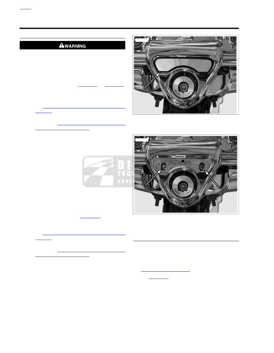
Gain access to upper handlebar clamp:

a.

Road King models:

See

Figure 2-81

and

Figure 2-82

.

Remove decorative plate from handlebar clamp
shroud.

b.

Fork mounted fairing models:

Remove fairing cap.

See

2.35 FAIRING CAP: FORK MOUNTED FAIRING

MODELS

.

c.

Frame mounted fairing models:

Remove instrument

bezel. See

2.39 INSTRUMENT BEZEL: FRAME

MOUNTED FAIRING MODELS

.

3.

Loosen rear screws on the upper handlebar clamp. On
frame mounted fairing models, loosen the front screws
instead.

4.

Position handlebars for rider posture and comfort.

5.

Verify that the knurled area on the outboard side of the
left side handlebar clamp is equal to that on the right side.

6.

Snug upper handlebar clamp screws.

7.

Slowly turn handlebars to the full right fork stop and full
left fork stop to be sure there is no contact with the fuel
tank and adjust as necessary.

8.

Tighten the upper handlebar clamp screws to 16-20 ft-lbs
(21.7-27.1 Nm).

9.

Reassemble:

a.

Road King models:

See

Figure 2-81

Install decor-

ative plate onto handlebar clamp shroud.

b.

Fork mounted fairing Models:

Install fairing cap.

See

2.35 FAIRING CAP: FORK MOUNTED FAIRING

MODELS

.

c.

Frame mounted fairing Models:

Install instrument

bezel. See

2.39 INSTRUMENT BEZEL: FRAME

MOUNTED FAIRING MODELS

.

10. If necessary, reposition the controls for rider comfort.

Beginning with top screw, tighten clamp screws to 72-108

in-lbs

(8.1-12.0 Nm).

11. Install the main fuse.

sm03840

Figure 2-81. Remove Decorative Plate (FLHR/C)

sm03838

Figure 2-82. Loosen Upper Handlebar Clamp Screws

(FLHR/C)

REMOVAL

1.

Remove the main fuse.

2.

Remove outer fairing or headlamp nacelle to gain access
to harness connectors.

3.

Disconnect twist grip sensor jumper harness. See

4.10 TWIST GRIP SENSOR

.

4.

See

Figure 2-83

Disconnect heated handgrip harness (3)

if equipped. It is not necessary to disconnect the handgrip
interconnect harness (2).

NOTE

Cover painted surfaces to prevent scratches or other damage.

HOME

2-70 2011 Touring Service: Chassis

5.

Gain access to upper handlebar clamp:

a.

Road King models:

Remove handlebar clamp

shroud. See

2.44 HEADLAMP NACELLE: ROAD

KING MODELS

.

b.

Fork mounted fairing models:

Remove fairing cap.

See

2.35 FAIRING CAP: FORK MOUNTED FAIRING

MODELS

. Remove radio (or storage box). See

7.33 ADVANCED AUDIO SYSTEM

.

c.

Frame mounted fairing models:

Remove instrument

nacelle. See

2.40 INSTRUMENT NACELLE: FRAME

MOUNTED FAIRING MODELS

.

6.

Remove right and left handlebar switch controls. See

7.40 HANDLEBAR SWITCH ASSEMBLIES

.

7.

Cut cable straps as necessary.

8.

Remove upper handlebar clamp screws, upper handlebar
clamp and handlebar.

2

3

1

sm06630

1. TGS jumper harness
2. Heated handgrip interconnect harness
3. Heated handgrip power

Figure 2-83. Handlebar Harness Connectors (FLHTK)

INSTALLATION

1.

Place handlebars on lower handlebar clamps. Install upper
handlebar clamp and loosely install clamp screws.

2.

Verify that the handlebars are centered, and snug upper
handlebar clamp screws.

3.

Slowly turn handlebars to the full right fork stop and full
left fork stop to be sure there is no contact with the fuel
tank and adjust as necessary.

4.

Tighten handlebar clamp front screws until upper and
lower handlebar clamps make contact.

5.

Tighten clamp rear screws to 16-20 ft-lbs (21.7-27.1 Nm).

6.

Tighten clamp front screws to 16-20 ft-lbs (21.7-27.1 Nm).

NOTE

A slight gap will exist between the upper and lower clamps at
the rear of the handlebars after tightening.

7.

Install right and left handlebar switch controls. See

7.40 HANDLEBAR SWITCH ASSEMBLIES

.

8.

Reassemble:

a.

Road King models:

Install handlebar clamp shroud.

See

2.44 HEADLAMP NACELLE: ROAD KING

MODELS

.

b.

Fork mounted fairing models:

Install fairing cap.

See

2.35 FAIRING CAP: FORK MOUNTED FAIRING

MODELS

Install radio (or storage box). See

7.33 ADVANCED AUDIO SYSTEM

.

c.

Frame mounted fairing models:

Install instrument

nacelle. See

2.40 INSTRUMENT NACELLE: FRAME

MOUNTED FAIRING MODELS

.

9.

Connect

twist

grip

sensor

jumper

harness.

See

4.10 TWIST GRIP SENSOR

.

10. See

Figure 2-83

. Connect heated handgrip harness (3),

if equipped.

11. Secure harnesses as necessary with

new

cable straps.

12. Install outer fairing or headlamp nacelle.

13. Install the main fuse.

Be sure that all lights and switches operate properly before
operating motorcycle. Low visibility of rider can result in
death or serious injury. (00316a)

14. Turn ignition/light key switch to IGNITION and test each

handlebar switch for proper operation.

After repairing the brake system, test brakes at low speed.
If brakes are not operating properly, testing at high speeds
can cause loss of control, which could result in death or
serious injury. (00289a)

15. Apply front brake hand lever to test operation of brake

lamp.

HOME

2011 Touring Service: Chassis 2-71

8

10

9

1

4

5

4

7

3

6

2

sm02933

1. Screw
2. Upper clamp
3. Lower clamp
4. Cup washer
5. Spacer
6. Rubber bushing
7. Bolt
8. Ground cable (left clamp only)
9. Flat washer (right clamp only)
10. Large flat washer (right clamp only)

Figure 2-84. Handlebar Clamp Assemblies

LEFT HANDGRIP

Removal

NOTE

The following procedure is for a conventional left handgrip. If
equipped with heated handgrips, see

2.23 HANDLEBARS,

Heated Handgrips

.

1.

Remove

left

handlebar

switch

controls.

See

7.40 HANDLEBAR SWITCH ASSEMBLIES

.

2.

Use a sharp blade to cut rubber and peel off handlebar.

3.

Thoroughly clean handlebar to remove all residual
adhesive.

Installation

1.

Apply a coat of Harley-Davidson Adhesive (Part No.
99839-95) to the inside surface of the

new

grip 1.0 in.

(25.4 mm) from the open end. Apply a coat to the end of
the handlebar.

NOTE

Align the pattern with the pattern on the right grip (with the
throttle fully closed).

2.

Immediately push grip completely onto end of handlebar
using a twisting motion. Do not hesitate when installing
grip or adhesive may set before installation is complete.

3.

Allow adhesive to cure for 6-8 hours at 70 °F (21 °C).

4.

Install

left

handlebar

switch

controls.

See

7.40 HANDLEBAR SWITCH ASSEMBLIES

.

HEATED HANDGRIPS

Remove Left Handgrip

1.

Remove main fuse.

2.

Remove outer fairing.

3.

See

Figure 2-85

. Disconnect and remove terminals from

heated handgrip interconnect (1) and power (2) con-
nectors.

NOTE

For connector service, see

A.12 DEUTSCH DT SEALED

CONNECTORS, Deutsch DT Sealed Connector Repair

.

4.

Fabricate a chaser wire made of mechanic's wire,
approximately 3 ft (91.4 cm) long, and attach to the har-
nesses. Wrap two or three turns of chaser wire around
terminals and wire leads of the harnesses, and wrap
junction with electrical tape, covering terminals and end
of chaser wire.

5.

Bend last few inches of free end of chaser wire into an "L"
shape to prevent it from being pulled too far into the
handlebar.

6.

Remove left handlebar switch housing and clutch lever.
Allow to hang. See

7.40 HANDLEBAR SWITCH ASSEM-

BLIES

.

7.

Apply glass cleaner to harnesses to act as a lubricant.

NOTE

When pulling harnesses, feed opposite end of harnesses and
mechanic's wire into handlebar.

8.

Slide handgrip off end of handlebar. Grasp harnesses and
gently pull from handlebar until they can be detached from
chaser wire.

HOME

2-72 2011 Touring Service: Chassis

2

1

sm06636

1. Heated handgrip interconnect harness
2. Heated handgrip power

Figure 2-85. Heated Handgrip Connectors

Install Left Handgrip

1.

Attach chaser wire to harnesses. Make sure electrical tape
wrap extends over end of harness conduit.

2.

Lubricate wire harness conduits with glass cleaner.

3.

Carefully feed harnesses into handlebar with one hand as
they are pulled with the other.

4.

Slide handgrip onto end of handlebar and pull slack from
wiring harnesses. Remove chaser wire from harnesses.

5.

Install terminals into connector housing cavities. Refer to

Table 2-15

.

NOTE

For connector service, see

A.12 DEUTSCH DT SEALED

CONNECTORS, Deutsch DT Sealed Connector Repair

.

6.

Mate connectors and secure harnesses with

new

cable

straps.

7.

Install left handlebar switch housing and clutch lever. See

7.40 HANDLEBAR SWITCH ASSEMBLIES

. Make sure

rim of handgrip fits into grooves in switch housings.

8.

Install outer fairing. Install main fuse.

Table 2-15. Left Heated Grip Connectors

COLOR

CAVITY

CONNECTOR

Red

1

Power

Black

2

Black/white

1

Interconnect

Black/white

2

Remove Right Handgrip

NOTE

This procedure covers only removal and installation of the
handgrip. For service of the TGS, see

4.10 TWIST GRIP

SENSOR

.

1.

Remove main fuse.

2.

Remove outer fairing.

Do not remove or install the master cylinder assembly
without first positioning a 5/32-inch (4 mm) thick insert
between the brake lever and lever bracket. Removing or
installing the master cylinder assembly without the insert
in place may result in damage to the rubber boot and
plunger on the front stoplight switch. (00324a)

3.

Remove right switch housing and master cylinder from
handlebar. See

7.40 HANDLEBAR SWITCH ASSEM-

BLIES

. Suspend out of the way.

4.

Pry end cap from handgrip and pull connector out through
end of handgrip.

NOTE

To remove the throttle handgrip, a slight tug may necessary.

5.

Pull handgrip off end of handlebar.

Install Right Handgrip

1.

Verify twist grip sensor is properly installed in end of
handlebar.

2.

Seat handgrip onto twist grip sensor.

3.

Using needle nose pliers, insert prongs of connector into
connector holes located in end of twist grip sensor.

4.

Pull handgrip off until it disengages TGS and rotate
handgrip to allow wires to wrap around connector. Engage
handgrip on TGS and rotate handgrip to verify proper
engagement. Install end cap.

5.

Install right switch control housing and front brake master
cylinder. See

7.40 HANDLEBAR SWITCH ASSEMBLIES

.

6.

Install outer fairing. Install main fuse.

RUBBER MOUNTS

Removal

1.

See

Figure 2-84

. Before removing handlebars, loosen

bolts (7) securing lower clamps (3) to upper fork bracket.

2.

Remove the handlebars. See

2.23 HANDLEBARS,

Removal

.

3.

See

Figure 2-84

Remove bolts (7), washer (10) and cup

washers (4).

4.

Remove lower handlebar clamp (3), flat washer (9) and
cup washer from top of upper fork bracket.

5.

Pull bushings (6) from fork bracket bore and spacers (5).

6.

Discard bushings.

HOME

2011 Touring Service: Chassis 2-73

sm02935

Figure 2-86. Remove Flat Washer and Upper Cup Washer

(Right Side)

sm02936

Figure 2-87. Remove Upper Bushing (Right Side)

sm02937

Figure 2-88. Remove Bolt, Large Washer, and Lower Cup

Washer (Right Side)

sm02938

Figure 2-89. Remove Spacer from Lower Bushing

Installation

1.

See

Figure 2-89

. Insert spacers into

new

bushings until

flush with outboard side of collar.

2.

Insert bushing into bore at bottom of upper fork bracket
fitting collar of bushing over lip of boss.

3.

See

Figure 2-87

Insert bushing into bore.

4.

Install large flat washer (right only) and cup washer on
bolt. Insert bolt into bushing fitting concave side of cup
washer over collar of bushing.

5.

Install cup washer over threaded end of bolt fitting concave
side over collar of bushing. Install ground wire ring terminal
(left side) or small flat washer (right side).

6.

Apply two or three drops of Loctite Medium Strength
Threadlocker 243 (blue) to threads of bolt. Install lower
handlebar clamp and turn bolt until snug.

7.

Install handlebars and upper handlebar clamp. See

2.23 HANDLEBARS, Installation

.

8.

Tighten lower clamp bolts to 30-40 ft-lbs (40.7-54.2 Nm).

9.

Complete assembly of motorcycle. See

2.23 HANDLE-

BARS, Installation

.

HOME

2-74 2011 Touring Service: Chassis

2.24

MIRRORS

ALL MODELS EXCEPT FLHX

Removal

1.

See

Figure 2-90

Remove acorn nut (1) and lock washer

(2).

2.

Remove mirror (3).

Installation

1.

Insert threaded stem of mirror into hole in clutch or brake
lever bracket.

2.

Install lock washer (2) and acorn nut (1).

3.

Adjust mirror as necessary and tighten acorn nut to 60-96

in-lbs

(6.8-10.8 Nm).

1

2

3

sm04981

1. Acorn nut
2. Lock washer
3. Mirror

Figure 2-90. Mirror Assembly (All Models Except FLHX)

FLHX

Removal

1.

Remove outer fairing. See

2.34 UPPER FAIRING AND

WINDSHIELD: FORK MOUNTED FAIRING MODELS

.

2.

See

Figure 2-91

Remove flange nut and plastic washer.

Remove mirror.

Installation

1.

See

Figure 2-92

With the bar and shield logo right side

up, insert threaded stud and align index pin (2) on swivel
block with hole in inner fairing.

NOTE

The letters "L" or "R" are stamped on the swivel blocks and
posts of the washers to identifyn left and right side installation.

2.

Install the plastic washer (4) engaging the small hole in
washer with index pin (2).

3.

Install flange nut (6) and tighten to 30-40

in-lbs

(3.4-4.5

Nm).

4.

Adjust mirror as necessary.

5.

Install outer fairing. See

2.34 UPPER FAIRING AND

WINDSHIELD: FORK MOUNTED FAIRING MODELS

.

sm04982

Figure 2-91. Remove Outer Fairing (FLHX)

1

5

2

3

6

4

sm04983

1. Threaded stud
2. Index pin
3. Swivel block stamp
4. Plastic washer
5. Stamped post
6. Flange nut

Figure 2-92. Left Side Mirror Assembly (FLHX)

HOME

2011 Touring Service: Chassis 2-75

2.25

SEAT

SEAT: MODELS WITHOUT TOUR-PAK

Removal

Detach passenger seat strap before removing seat. Failure
to do so can result in damage to rear fender paint. (00225a)

1.

Open left side saddlebag.

2.

See

Figure 2-93

. Remove screw and release passenger

seat strap from seat strap bracket.

3.

Remove screw to release seat from top of rear fender.

4.

See

Figure 2-94

. Push seat rearward to free slot from

tongue on rear fuel tank bracket.

Installation

1.

Place seat in position.

2.

See

Figure 2-94

Firmly push front of seat downward and

then forward until slot (1) engages tongue (2).

3.

Secure seat to fender with screw and tighten to 48-72

in-

lbs

(5.4-8.1 Nm).

NOTE

If seat retention nut is damaged or lost, see

2.25 SEAT, Seat

Retention Nut Replacement

for instructions.

4.

See

Figure 2-93

Start screw to fasten passenger seat

strap to seat strap bracket. Feed end of strap into slot of
seat strap bracket and tighten screw to 48-72

in-lbs

(5.4-

8.1 Nm).

5.

Close left side saddlebag.

After installing seat, pull upward on seat to be sure it is
locked in position. While riding, a loose seat can shift
causing loss of control, which could result in death or
serious injury. (00070b)

sm05891

Figure 2-93. Seat Strap Bracket Screw

1

2

sm05893

1. Seat bottom slot
2. Fuel tank rear bracket tongue

Figure 2-94. Seat Mounting

SEAT: MODELS WITH TOUR-PAK

Removal

1.

Open left side saddlebag.

2.

See

Figure 2-93

Remove screw to release passenger

seat strap from seat strap bracket.

3.

Open Tour-Pak to move passenger seat backrest out of
the way.

NOTE

The seat mounting screw can not be accessed with the Tour-
Pak mounted in the forward position. If installed in the forward
position, temporarily install in the rearward position. Install back
in the original position after installing seat. See

2.28 TOUR-

PAK

for more information.

4.

Remove screw to release seat from top of rear fender.

5.

See

Figure 2-94

. While pushing seat forward, raise rear

of seat until bracket clears Tour-Pak. Push seat rearward
to free slot from tongue on rear fuel tank bracket.

6.

Remove seat.

HOME

2-76 2011 Touring Service: Chassis

Installation

1.

See

Figure 2-94

. Place seat in position.

NOTE

To protect finish of Tour-Pak, cover rear seat mounting bracket
with palm of hand.

2.

Hold rear of seat approximately 3 in. (76.2 mm) above
fender and use the other hand to push front of seat
downward and forward until slot (1) engages tongue (2).

3.

Secure seat to fender with screw and tighten to 48-72

in-

lbs

(5.4-8.1 Nm).

NOTE

If seat retention nut is damaged or lost, see

2.25 SEAT, Seat

Retention Nut Replacement

for instructions.

4.

See

Figure 2-93

Start screw to fasten passenger seat

strap to seat strap bracket. Feed end of strap into slot of
seat strap bracket and tighten screw to 48-72

in-lbs

(5.4-

8.1 Nm).

5.

Close left side saddlebag.

After installing seat, pull upward on seat to be sure it is
locked in position. While riding, a loose seat can shift
causing loss of control, which could result in death or
serious injury. (00070b)

SEAT: ROAD KING MODELS

Removal

1.

Remove left side saddlebag.

2.

Remove screw securing passenger seat strap and
saddlebag front mounting bracket.

3.

See

Figure 2-95

Draw passenger seat strap to right side

of motorcycle, passing through slots in seat on FLHRC
models.

4.

Remove screw to release seat from top of rear fender.

5.

See

Figure 2-94

. Push seat rearward to free slot (1) from

tongue (2).

6.

Remove seat.

Installation

1.

Place seat in position.

2.

See

Figure 2-94

Firmly push front of seat downward and

then forward until slot (1) engages tongue (2).

3.

Secure seat to fender with screw and tighten to 48-72

in-

lbs

(5.4-8.1 Nm).

NOTE

If seat retention nut is damaged or lost, see

2.25 SEAT, Seat

Retention Nut Replacement

for instructions.

4.

See

Figure 2-95

. Draw free end of passenger seat strap

to left side of motorcycle, passing through slots in seat on
FLHRC models.

sm04967

Figure 2-95. Route Passenger Seat Strap Through Slots

(FLHRC)

5.

Install passenger seat strap and saddlebag front mounting
bracket. Do not tighten screw at this time.

6.

Install left side saddlebag.

7.

Tighten saddlebag front mounting bracket screw to 60-96

in-lbs

(6.8-10.8 Nm).

After installing seat, pull upward on seat to be sure it is
locked in position. While riding, a loose seat can shift
causing loss of control, which could result in death or
serious injury. (00070b)

SEAT RETENTION NUT REPLACEMENT

1.

See

Figure 2-96

. Remove retention washer (4) and remove

retention nut from fender.

2.

See inset of

Figure 2-96

. Slide

new

retention nut onto a

cable strap as shown. Insert into fender hole and hold with
cable strap.

3.

Align tab (3) on retention nut and hold nut snug against
underside of rear fender. Orient the retention washer (4)
and install as shown. Remove cable strap.

HOME

2011 Touring Service: Chassis 2-77

1

2

4

3

sm04964

1. Rear fender
2. Retention nut
3. Tab
4. Retention washer

Figure 2-96. Install Seat Retention Nut

SEAT BUMPER

NOTE

FLHX, FLTRX and FLTRU models utilize a seat bumper to
minimize seat movement.

1.

See

Figure 2-97

Install a seat bumper to each upper frame

rail (1), in the orientation shown (arrows forward).

2.

Install a fastener (3) in each bumper and tighten to 80-120

in-lbs

(9.0-13.6 Nm).

1

2

3

sm06984

1. Upper frame rail
2. Seat bumper (2)
3. Fastener (2)

Figure 2-97. Seat Bumper Installation

HOME

2-78 2011 Touring Service: Chassis

2.26

SADDLEBAGS

REMOVAL

1.

Open saddlebag.

2.

See

Figure 2-98

. Rotate each stud (1) 1/4 turn counter-

clockwise. Remove studs and flat washers from grommets.

NOTE

Some HDI motorcycles have the bail wire removed from the
stud. Turn the stud with a screwdriver.

3.

Remove saddlebag.

1

2

3

sm05804

1. Stud
2. Lower support rail
3. Grommet

Figure 2-98. Saddlebag Quick-Release Fasteners

INSTALLATION

1.

Position saddlebag on motorcycle aligning holes in grom-
mets with those in front and rear mounting brackets.

NOTE

Replace grommets if torn or deteriorated. Moisten new
grommet with glass cleaner or soapy water and work smaller
OD through hole into saddlebag.

2.

Place flat washers on studs.

3.

Hold groove at end of stud horizontal and insert stud
through grommet. When groove engages wire form spring
in mounting bracket, turn stud clockwise 1/4 turn until it
locks in place.

NOTES

Some HDI motorcycles have the bail wire removed from
the stud. Turn the stud with a screwdriver.

See

Figure 2-98

. Molded rubber insert at bottom of

saddlebag must fit snugly on lower saddlebag support rail
(2). If saddlebag is not fully seated, loosen bolt securing
front mounting bracket and adjust saddlebag fit. Tighten
mounting bracket bolt to 12-15 ft-lbs (16.3-20.3 Nm).

4.

Close saddlebag.

HOME

2011 Touring Service: Chassis 2-79

2.27

SADDLEBAG SERVICE

SADDLEBAG HARDWARE

Removal

1.

Lay clean pad or blanket on work bench to protect painted
surfaces of saddlebag.

2.

Remove saddlebag from motorcycle leaving lid open. See

2.26 SADDLEBAGS

.

3.

Lay saddlebag flat on pad with the inboard side facing up
and the lid closest to you.

4.

Remove two screws to release check strap from lid.

5.

Remove two screws to release check strap from
saddlebag.

6.

Remove two remaining screws to remove latch from
saddlebag.

NOTE

This procedure assumes that the latch is NOT removed from
the saddlebag lid. If there is doubt as to whether the procedure
can be accomplished without scratching painted surfaces of
the lid, then remove the five remaining screws to completely
remove latch.

7.

Position lid right side up with latch closest to you.

8.

See upper frame of

Figure 2-99

Raise latch slightly and

rotate hinge on inboard side so that it is topside with the
two plastic rub bars pointed upward.

9.

See lower frame of

Figure 2-99

Rotate rub bar section of

hinge to expose hinge pin and spring. Using a flat tip
screwdriver, carefully bend crimped end link outward.

NOTE

The end link on opposite side of hinge has a weld spot that
prevents pin removal.

10. Reposition lid so that it is upside down with the latch

farthest from you. Rotate hinge so that plastic rub bars
are positioned beneath latch and spring is topside.

11. See upper frame of

Figure 2-100

Using a needle nose

pliers, grasp pin through opening just outboard of the
spring and push toward the crimped link side. Work pin in
this manner until end can be seen exiting crimped link. If
necessary, pry crimped link outward a little more to achieve
the desired result.

12. See lower frame of

Figure 2-100

Grasping end with needle

nose pliers, slowly pull pin from links until spring can be
slid off opposite end. Only pull pin as far as necessary to
remove spring.

sm03539

Figure 2-99. Lid Right Side Up With Latch on Near Side

HOME

2-80 2011 Touring Service: Chassis

sm03540

Figure 2-100. Lid Up Side Down With Latch on Far Side

Installation

1.

See lower frame of

Figure 2-100

. Slide

new

spring onto

end of pin and orient spring.

2.

Slide pin back through links. Using tapered end of needle
nose pliers, push end of pin into crimped link.

3.

See

Figure 2-99

Reposition lid so that it is right side up

with latch closest to you. As before, raise latch slightly and
rotate hinge on inboard side so that it is topside with plastic
rub bars pointing upward. Now rotate rub bar section of
hinge to expose hinge pin and spring.

4.

Holding lid down with elbow, if necessary, use a pliers to
bend crimped link back into its original position, so that
pin is captured and will not back out of hinge.

5.

Reposition lid so that it is upside down with the latch
farthest from you. Move saddlebag forward for reinstalla-
tion of lid. Align four holes in saddlebag with those in latch.

6.

Install two inboard screws to fasten latch to saddlebag.
Alternately tighten screws to 20-25

in-lbs

(2.3-2.8 Nm).

7.

Align holes in check strap with those in lid and saddlebag.
Orient check strap so that logo is topside with the bottom
of the bar and shield on the lid side.

8.

Install two screws to fasten check strap and latch to
saddlebag. Alternately tighten screws to 20-25

in-lbs

(2.3-

2.8 Nm).

9.

Install two screws to fasten check strap to lid. Alternately
tighten screws to 18-20

in-lbs

(2.0-2.3 Nm).

10. Close saddlebag and install on motorcycle. See

2.26 SADDLEBAGS

.

SADDLEBAG GUARD/SUPPORT RAIL

Removal

1.

Remove saddlebag. See

2.26 SADDLEBAGS

.

2.

See

Figure 2-101

. Remove fasteners (8) that secure

muffler mount to muffler.

3.

Disassemble saddlebag guard, support and/or rails as
necessary.

Installation

1.

See

Figure 2-101

. Assemble saddlebag guard, support

and/or rails as necessary. Install grab strap (9) along with
forward mounting bracket. Air suspension fitting (10) is
also secured on left side by fastener (2). Refer to

Table 2-16

for the correct fastener torque specifications.

2.

Secure muffler to lower rail (12 or 13). Install screws (8)
and tighten to 96-144

in-lbs

(10.8-16.3 Nm).

3.

Install saddlebag. See

2.26 SADDLEBAGS

.

Table 2-16. Saddlebag Support/Guard Fastener Torque

Specifications

TORQUE

ITEM

12-15 ft-lbs (16.3-20.3 Nm)

1

15-20 ft-lbs (20.3-27.1 Nm)

2

15-20 ft-lbs (20.3-27.1 Nm)

3

32-36 ft-lbs (43.4-48.8 Nm)

4

70-100

in-lbs

(7.9-11.3 Nm)

5

72-120

in-lbs

(8.1-13.6 Nm)

6

30-50

in-lbs

(3.4-5.6 Nm)

7

15-20 ft-lbs (20.3-27.1 Nm)

14

HOME

2011 Touring Service: Chassis 2-81

2

10

2

13

12

11

8

1

4

9

6

4

5

15

14

3

7

sm05806

9.

1.

Grab strap

Forward mounting bracket fastener

2.

10.

Support-to-fender fastener

Air suspension fitting

11.

3.

Side rails (FLHTC, FLHTCU)

Side rail-to-support fastener

4.

12.

Guard-to-frame fastener

Front and lower rails (All except FLTRU, FLHX,
FLTRX)

5. Support rail-to-guard fastener

13.

6.

Support assembly (FLTRU, FLHX, FLTRX)

Side guard-to-front guard fastener

7.

14.

Rail clamp fasteners

Rear fender support-to-saddlebag support fastener

15.

8.

Flange locknut

Muffler mount fasteners

Figure 2-101. Saddlebag Support

HOME

2-82 2011 Touring Service: Chassis

2.28

TOUR-PAK

REMOVAL/INSTALLATION

Removal

1.

Remove map pouch and inner liner or mat from Tour-Pak,
as equipped.

2.

See

Figure 2-102

Separate radio antenna cable connector

(8), Tour-Pak lights connector (1), and accessory power
outlet connector (2) if equipped.

3.

Pull grommet (3) into Tour-Pak and remove from harness.

4.

Feed harness and antenna cable through hole in Tour-
Pak.

5.

Release rear headset receptacle from bracket at bottom
of left side speaker box.

6.

Disconnect CB antenna cable connector (6).

7.

Pull right side grommet (4) into Tour-Pak and remove from
antenna cable. Feed CB antenna cable through hole in
Tour-Pak.

8.

Models with rear speakers:

See

Figure 2-103

Remove

three fasteners (1) and flat washers to release each
speaker box (2). Lay speakers on the seat.

NOTE

Make note of which set of locating holes are used to mount
Tour-Pak.

9.

Remove four screws and lock washers (4). Hold the Tour-
Pak as the bolts are removed to prevent it from accident-
ally tipping. Remove Tour-Pak.

1

8

2

3

4

7

6

5

sm06601

1. Tour-pak lights connector
2. Power outlet connector (if equipped)
3. Grommet
4. Grommet
5. Power outlet (if equipped)
6. CB antenna connector
7. Radio antenna ground
8. Radio antenna connector

Figure 2-102. Tour-Pak Connectors

2

3

4

1

sm05812

1. Speaker box fasteners
2. Speakers
3. Ground ring terminal
4. Screws and lock washers (4)

Figure 2-103. Tour-Pak Mounting Bolts

Installation

1.

Place Tour-Pak on luggage rack and open lid. Hold the
Tour-Pak to prevent it from accidentally tipping.

2.

See

Figure 2-103

Install four screws (4) with radio antenna

ground ring terminal (3) under lock washer of left-rear bolt.

3.

Tighten screws in a crosswise pattern to 96-120

in-lbs

(10.8-13.6 Nm).

NOTE

The lower screws that secure the right speaker box also secure
the power outlet (if equipped).

4.

Install speaker boxes and secure with screws and flat
washers (1). Tighten fasteners to 25-35

in-lbs

(2.8-4.0

Nm).

5.

FLHTCU:

See

Figure 2-102

Pass CB antenna cable

through right hole in Tour-Pak and install grommet (4) with
the larger OD facing inside.

6.

Install CB antenna cable connector (6). Capture cable in
clips at bottom of Tour-Pak.

7.

Capture rear headset receptacle in bracket at bottom of
left side speaker box.

8.

Feed Tour-Pak harness through left hole in Tour-Pak and
install grommet (3) with the larger OD facing inside.

9.

Mate connectors (1, 2).

10. Mate radio antenna cable connector (8) to antenna. Cap-

ture cable in clips at bottom of Tour-Pak.

HOME

2011 Touring Service: Chassis 2-83

11. Install molded liner and map pouch or rubber mat, as

equipped.

ADJUSTMENT

NOTE

The Tour-Pak can be moved forward or rearward approximately
1 in. (25.4 mm) for best passenger comfort.

1.

Remove map pouch and molded liner or rubber mat, as
equipped.

2.

See

Figure 2-103

. Remove four screws and lock washers

(4) from inside Tour-Pak. Hold the Tour-Pak to prevent it
from accidentally tipping.

3.

Move Tour-Pak to the desired position.

4.

Install four screws (4) with radio antenna ground ring ter-
minal (3) under lock washer of left-rear screw.

5.

Tighten screws in a crosswise pattern to 96-120

in-lbs

(10.8-13.6 Nm).

6.

Verify that wire harness to Tour-pak is not bunched or
stretched at any point. Rearrange wire harness if neces-
sary and install

new

cable straps.

7.

Install molded liner and map pouch or rubber mat as
equipped.

LUGGAGE RACK/TOUR-PAK SUPPORT

Removal

1.

Remove cable straps as required to free harnesses from
luggage rack. Take note of cable strap locations for reas-
sembly.

2.

See

Figure 2-104

. Remove fastener (5), seat strap (4),

and forward saddlebag bracket (3).

3.

Remove fastener (6) and remove cover (1).

4.

Remove two fasteners (2) from each side and remove
luggage rack.

6

5

4

3

1

2

sm05864

4.

1.

Seat strap

Cover (2)

2.

5.

Fastener, luggage rack to fender support (4)

Cover fastener, front (2)

6.

3.

Cover fastener, rear (2)

Forward saddlebag bracket (2)

Figure 2-104. Luggage Rack

Assembly and Installation

1.

See

Figure 2-104

. Install luggage rack and start fasteners

(2 and 6).

2.

Tighten fasteners (2) to 15-20 ft lbs (20.3-27.1 Nm).

3.

Remove fastener (6) and install cover (1). Secure cover,
front saddlebag bracket (3), and seat strap (4) with
fastener (5) and flat washer. Do not tighten at this time.

4.

Install fastener (6) and tighten to 15-20 ft lbs (20.3-27.1
Nm).

5.

Secure harnesses as necessary to the luggage rack.

6.

Secure saddlebags, rotating brackets (3) as necessary to
align with forward saddlebag fastener. Verify saddlebag
is securely engaged with lower support and tighten
fastener (5) to 12-15 ft lbs (16.3-20.3 Nm).

HOME

2-84 2011 Touring Service: Chassis

2.29

TOUR-PAK SERVICE

LOCKSET

Removal

NOTE

For replacement of the lockset catch, see

2.29 TOUR-PAK

SERVICE, Latches/Lockset Catch

.

1.

See

Figure 2-105

. Remove hex nut (7), internal tooth

lockwasher (6), cam hook (5) and cam washer (4).
Remove jam nut and lock guide.

2.

See

Figure 2-106

Remove lockset. Remove thin washer

(2) from threaded body of lockset.

1

4

5

7

6

3

2

sm03550

1. Lock guide
2. Jam nut
3. Lockset
4. Cam washer
5. Cam hook
6. Lockwasher
7. Hex nut

Figure 2-105. Lockset Assembly

2

1

4

3

6

5

sm03551

1. Lockset
2. Thin washer
3. Cam stop
4. Threaded stud
5. Cam washer
6. Cam hook

Figure 2-106. Lockset Mechanism

Installation

1.

See

Figure 2-106

Slide thin washer (2) down threaded

body of lockset.

2.

With cam stop (3) facing toward front of Tour-Pak lid, install
lockset into hole.

3.

See

Figure 2-105

. Install lock guide (1) as shown.

4.

Install jam nut and tighten to 30-45

in-lbs

(3.4-5.1 Nm).

5.

Verify that groove in threaded stud of lockset is facing rear
of Tour-Pak lid. Use key to rotate threaded stud, if neces-
sary.

6.

See

Figure 2-106

. Align cam hook (6) and cam washer

(5) as shown. With the cam hook toward the front of Tour-
Pak lid and cam washer on the inboard side, slide
assembly down threaded stud.

7.

Install internal tooth lockwasher and hex nut onto threaded
stud. Tighten hex nut to 25-35

in-lbs

(2.8-4.0 Nm).

HINGES

TOOL NAME

PART NUMBER

RIVET TOOL

HD-39787A

Removal

1.

Remove tether. See

2.29 TOUR-PAK SERVICE, Tether

.

2.

Remove screw.

3.

Remove hinge pin.

4.

Repeat previous steps to remove second hinge pin.
Remove Tour-Pak lid.

5.

Drill out rivets from inside Tour-Pak.

6.

Remove hinge and backplates.

Installation

1.

With the head of the

new

rivet on the outboard side of the

Tour-Pak, slide rivet through holes in hinge, Tour-Pak and
backplate.

2.

See

Figure 2-107

. Obtain RIVET TOOL (Part No. HD-

39787A).

3.

Orient tool so that head of rivet is seated in depression of
drive head. Turn adjuster thumbscrew in or out of handle
until both ends of rivet are captured.

4.

Slowly squeeze handle of tool to compress rivet. Turn
adjuster thumbscrew slightly in a clockwise direction and
then squeeze handle again to further compress rivet.
Repeat step as necessary until rivet is fully installed.

NOTE

Compress rivet in small increments only to provide best
retention and alignment of parts, and avoid possible damage
to tool and painted surfaces of Tour-Pak.

5.

Repeat previous steps to install remaining rivets.

6.

Install lid onto Tour-Pak engaging upper and lower hinges.

HOME

2011 Touring Service: Chassis 2-85


Content      ..     13      14      15      16     ..