Harley Davidson 2011 Touring Models. Service Manual - page 18
 

  Главная      Harley Davidson     Harley Davidson 2011 Touring Models. Service Manual


Search            copyright infringement  


Content      ..     16      17      18      19     ..


Harley Davidson 2011 Touring Models. Service Manual - page 18


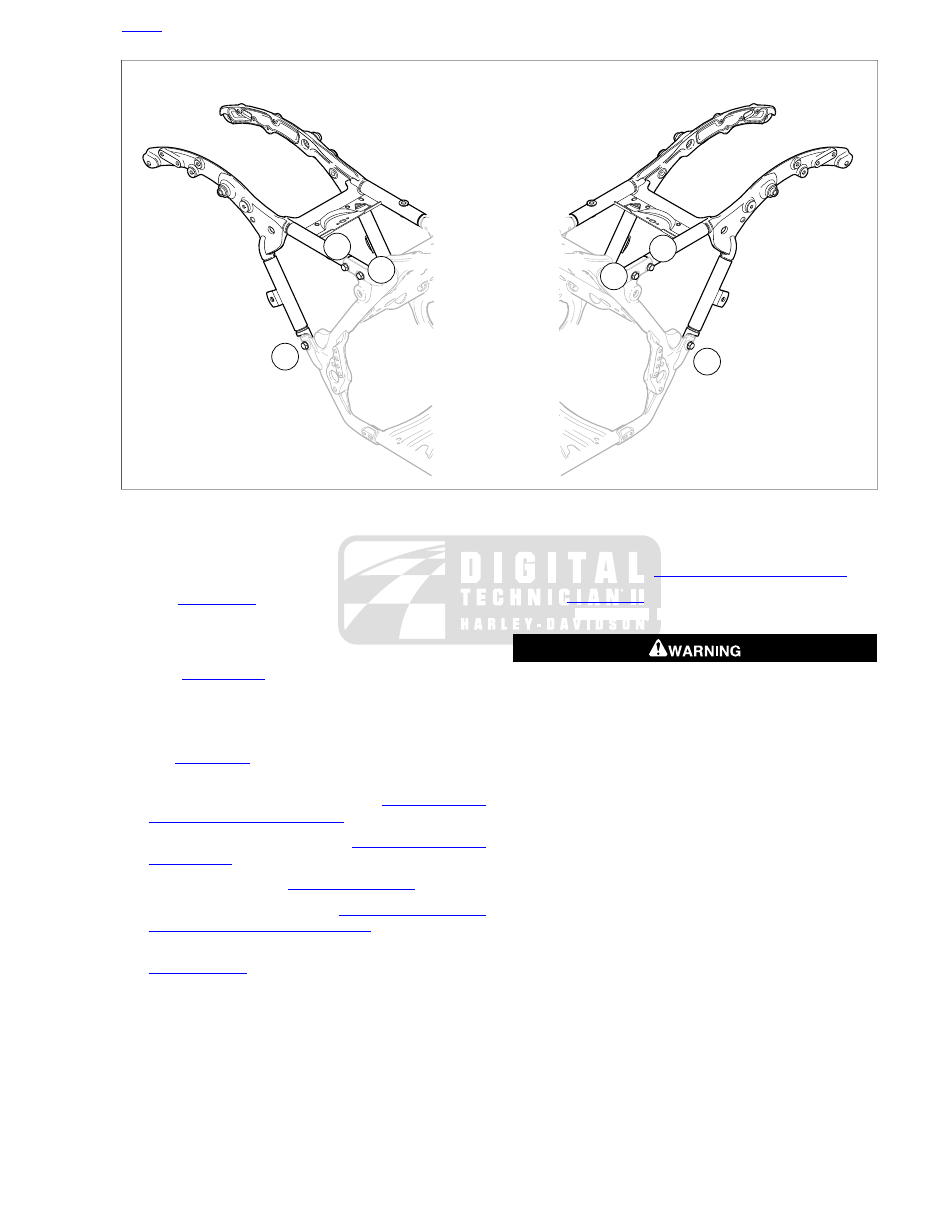
1

3

5

4

2

6

sm05877

Figure 2-159. Rear Frame Torque Sequence

Installation

1.

See

Figure 2-158

Fit the rear frame to the main frame

and start two lower fasteners (2) with hardened washers
(3). Install four remaining upper fasteners and hardened
washers.

2.

See

Figure 2-159

Tighten rear frame fasteners in

sequence shown to 40-45 ft-lbs (54.2-61.0 Nm).

3.

Secure left-side electrical caddy to rear frame and tighten
fastener to 72-96

in-lbs

(8.1-10.8 Nm).

4.

See

Figure 2-157

. Secure upper battery tray to rear frame.

Tighten fasteners (2) to 72-96

in-lbs

(8.1-10.8 Nm).

5.

Install luggage rack if equipped. See

2.28 TOUR-PAK,

Luggage Rack/Tour-Pak Support

.

6.

Install shock absorbers. See

2.20 REAR SHOCK

ABSORBERS

.

7.

Install rear fender. See

2.46 REAR FENDER

.

8.

Install saddlebag supports. See

2.27 SADDLEBAG SER-

VICE, Saddlebag Guard/Support Rail

.

9.

FLHTC/U,

FLHTK,

FLTRU:

Install

Tour-Pak.

See

2.28 TOUR-PAK

.

10. Secure harnesses to each side of rear frame and luggage

rack with cable straps. Position straps as noted during
disassembly.

11. Install saddlebags.

12. Install battery. See

1.23 BATTERY MAINTENANCE

.

13. See

Figure 2-157

Install top caddy and tighten fasteners

(1) to 72-96

in-lbs

(8.1-10.8 Nm).

After installing seat, pull upward on seat to be sure it is
locked in position. While riding, a loose seat can shift
causing loss of control, which could result in death or
serious injury. (00070b)

14. Install the seat.

Thread Repair

NOTES

Never re-tap the threaded holes in the rear frame to repair
damaged threads. Always use the following procedure to
provide repair.

If more than one threaded hole is damaged on a given
side, or if a thread repair has previously been done, the
rear frame must be replaced. Never repair more than one
hole per side.

1.

Remove the damaged fastener.

2.

Drill out damaged threads and install the appropriate size
thread repair insert.

3.

Install

new

fastener with hardened washer and tighten to

the proper torque.

HOME

2011 Touring Service: Chassis 2-127

2.49

FOOTBOARDS AND FOOTRESTS

RIDER FOOTBOARDS

Removal

When lifting a motorcycle using a jack, be sure jack con-
tacts both lower frame tubes where down tubes and lower
frame tubes converge. Never lift by jacking on cross-
members, oil pan or other housings. Failure to comply can
cause serious damage resulting in the need to perform
major repair work. (00586c)

1.

Left side footboard fasteners also secure the jiffy stand
bracket. If removing left side footboard, raise motorcycle

with a suitable lifting device to remove weight from jiffy
stand.

2.

See

Figure 2-160

Remove screw (5) and lockwasher (6).

3.

Remove screw (8), lockwasher (9) and flange nut (11).

4.

Remove footboard and bracket assembly from motorcycle.

Installation

1.

See

Figure 2-160

Install footboard and bracket assembly

and secure with screws (5, 8), lockwashers (6, 9), and
flange nut (11).

2.

Tighten screws to 36-42 ft-lbs (48.8-57.0 Nm).

1

3

12

4

3

5

6

5

8

9

14

13

6

7

8

9

11

10

4

11

2

sm05850

8.

1.

Socket head screw, long

Rubber pad

2.

9.

Footboard

Lockwasher

10.

3.

Right forward bracket

Pivot screw nut (2)

4.

11.

Pivot screw (2)

Flange nut

12.

5.

Left rear bracket

Socket head screw, short

6.

13.

Lockwasher

Jiffy stand bracket

14.

7.

Left forward bracket

Right rear bracket

Figure 2-160. Rider Footboards (Typical) (Quantities shown are for each footboard)

Disassembly

NOTE

If only replacing the rubber pad, refer to step 1 below and then
see steps 3-4 under ASSEMBLY.

1.

Tilt footboard upward. From bottom of footboard, use a
large flat blade screwdriver to push four rubber anchors
on pad up through holes in footboard.

2.

See

Figure 2-160

. Remove nuts (3) and pivot screws (4)

from underside of footboard.

3.

Remove footboard from brackets.

Assembly

1.

Place footboard into position between brackets and install
pivot screws (4) so that the nuts (3) will be on the inboard
side.

HOME

2-128 2011 Touring Service: Chassis

NOTE

The bottom of FLHX footboards are stamped L(eft) or R(ight)
to verify proper installation.

2.

Install nuts (3) onto pivot screws and tighten to 60-80

in-

lbs

(6.8-9.0 Nm).

3.

Moisten four rubber anchors on bottom of

new

pad (1)

with soapy water.

4.

Place pad into position on footboard. From bottom of
footboard, use pliers to pull rubber anchors through holes
in footboard.

PASSENGER FOOTBOARD

Removal

See

Figure 2-161

. Remove screw (2), lockwasher (3), screw

(7) and footboard/bracket assembly from frame.

Disassembly

1.

See

Figure 2-161

Use a small flat blade screwdriver to

push rubber beads on pad bottom through holes in foot-
board. Remove pad.

2.

Using a brass drift and mallet, tap two pivot pins (9) toward
center of footboard and remove.

3.

Remove footboard from footboard bracket.

4.

Remove steel ball (4) and spring (5).

Assembly

1.

See

Figure 2-161

Place spring (5) and ball (4) into hole

in footboard bracket.

2.

Place footboard into position on bracket and install pivot
pins (9) from the outboard side. Using a brass drift and
mallet, tap pins until centered in lugs of bracket.

6

3

4

9

7

8

1

5

2

sm02925a

1. Rubber pad
2. Upper screw
3. Lockwasher
4. Steel ball
5. Spring
6. Footboard bracket
7. Lower screw
8. Footboard
9. Pivot pin (2)

Figure 2-161. Passenger Footboard

3.

Moisten rubber beads on pad with soapy water. Use
needle nose pliers to pull rubber beads through holes in
footboard.

4.

Engage nubs on inboard corners of pad with holes in
footboard.

Installation

NOTE

Passenger footboards can be installed to one of three positions.
To install footboards in a new position, remove plastic plugs
from holes in frame.

1.

If reusing screws, apply a drop of Loctite Threadlocker
243 (blue) to the threads of each screw.

2.

See

Figure 2-161

. Secure bracket (6) with screw (2),

lockwasher (3) and screw (7).

a.

Tighten upper screw (2) to 36-42 ft-lbs (48.8-56.9
Nm).

b.

Tighten lower screw (7) to 48-72

in lbs

(5.4-8.1 Nm).

PASSENGER FOOTREST: FLHX, FLTRX

Removal

See

Figure 2-162

Remove screw (9) and lockwasher (10) to

remove footrest bracket from frame.

Disassembly

1.

See

Figure 2-162

. Remove screw (1). Remove rubber pad

(2) from footrest.

2.

Remove footrest (3) from footrest mount.

HOME

2011 Touring Service: Chassis 2-129

3.

Remove retaining ring (4) and pivot pin (5).

4.

Remove footrest mount (6) and wave spring (7).

Assembly

1.

See

Figure 2-162

Holding wave spring in place with con-

cave side against bracket, install footrest with the rounded
side of the pivot end up.

2.

Install pivot pin and secure with

new

retaining ring.

3.

Install footrest onto footrest mount and install rubber pad
into footrest.

4.

Apply a drop of Loctite Medium Strength Threadlocker
243 (blue) to threads of screw (1) and install.

5.

Rotate footrest so that the rubber pad is topside and
tighten screw to 15-20 ft-lbs (20-27 Nm).

4

1

8

10

9

5

2

3

6

7

sm02926

1. Socket screw
2. Rubber pad
3. Footrest
4. Retaining ring
5. Pivot pin
6. Footrest mount
7. Wave spring
8. Footrest bracket
9. Socket screw
10. Lockwasher

Figure 2-162. Passenger Footrest (FLHX, FLTRX)

Installation

1.

Locate pin on footrest bracket into hole in frame.

NOTE

Passenger footrests can be adjusted to one of three positions.
To move footrests to a new position, remove plastic plugs from
holes in frame as necessary.

2.

See

Figure 2-162

Install screw (9) and lockwasher (10).

Tighten screw to 36-42 ft-lbs (48.8-56.9 Nm).

HOME

2-130 2011 Touring Service: Chassis

2.50

JIFFY STAND

GENERAL

The jiffy stand locks when placed in the full forward (down)
position with vehicle weight on it. If the jiffy stand is not
in the full forward (down) position with vehicle weight on
it, the vehicle can fall over which could result in death or
serious injury. (00006a)

Always park motorcycle on a level, firm surface. An
unbalanced motorcycle can fall over, which could result
in death or serious injury. (00039a)

LEG REMOVAL

Block vehicle under frame such that vehicle will not fall
when jiffy stand is removed. Failure to properly block
vehicle could result in death or serious injury. (00462b)

When lifting a motorcycle using a jack, be sure jack con-
tacts both lower frame tubes where down tubes and lower
frame tubes converge. Never lift by jacking on cross-
members, oil pan or other housings. Failure to comply can
cause serious damage resulting in the need to perform
major repair work. (00586c)

1.

Support the motorcycle with a suitable lifting device so it
is upright and level. Jiffy stand should be able to move
through its full range of travel without the weight of the
motorcycle resting on it.

2.

See

Figure 2-165

. Move jiffy stand to the full forward

(down) position. Remove hex bolt (4), lockwasher (3), flat
washer (2) and leg stop (5).

3.

Swing jiffy stand forward beyond the normal down position
and remove end of spring (9) from jiffy stand. Remove leg
(8) from bracket. Remove other end of spring from frame
weldment.

4.

Inspect components for worn or damaged parts. Replace
parts as necessary.

LEG INSTALLATION

1.

Apply SILVER GRADE ANTI-SEIZE (part number 98960-
97) to area of leg that rotates within the bracket.

NOTE

See

Figure 2-164

Verify that end of spring enters hole from

front of leg weldment. If end of spring enters hole from rear of
weldment, spring coil will rub on leg when exercised.

2.

Install end of spring into hole in frame weldment. Insert
leg up through bracket. Swing jiffy stand forward beyond
the normal down position and install other end of spring
into hole in leg weldment.

If leg stop is incorrectly installed, excessive wear can allow
vehicle to fall when rested on jiffy stand, which could result
in death or serious injury. (00479b)

3.

See

Figure 2-163

Holding leg at the normal forward

(down) position, install stop (1) over threaded end with the
stamped side down. Verify that the longer side of the stop
faces the rear of the motorcycle. Install flat washer, lock-
washer and hex screw. Tighten hex screw to 15-20 ft-lbs
(20.3-27.1 Nm).

3

2

1

sm05949

1. Leg stop (longer side faces rear)
2. Hex screw, lockwasher and flat washer
3. Bracket

Figure 2-163. Leg Stop Orientation in Full Forward (Down)

Position

HOME

2011 Touring Service: Chassis 2-131

1

2

3

sm05859

1. Connector location
2. Cable strap
3. Sensor fastener

Figure 2-166. Jiffy Stand Interlock Sensor

Installation

1.

Move jiffy stand to full forward (down) position.

2.

See

Figure 2-166

. Install sensor into bore of jiffy stand

bracket.

3.

If reusing fastener (3), apply a small dab of Loctite Medium
Strength Threadlocker 243 (blue) to threads before
installation. Install fastener and tighten to 96-120

in-lbs

(10.8-13.6 Nm).

4.

Route connector and cable over top of frame weldment,
staying rear of front frame down tube, and to area below
voltage regulator.

5.

Connect jiffy stand interlock sensor connector and push
anchor into hole in front frame cross member.

6.

Install

new

cable strap (2) to capture cable. Cut any

excess cable strap material.

HOME

2011 Touring Service: Chassis 2-133

2.51

FRONT ENGINE MOUNT

REMOVAL

1.

Remove right lower fairing, if present. See

2.33 LOWER

FAIRING AND ENGINE GUARD

.

2.

Remove right side rider footboard. See

2.49 FOOT-

BOARDS AND FOOTRESTS

.

3.

Place a jack under the oil pan and use a block of wood
between the jack and the oil pan to distribute pressure
across the length of the casting. Raise the jack until firm
contact is made with the bottom of the oil pan.

4.

Remove rear brake pedal from master cylinder and engine
mount end cap. See

2.14 REAR BRAKE MASTER CYL-

INDER

.

5.

Remove rear master cylinder from engine mount end cap.

6.

See

Figure 2-167

. Loosen, but do not remove, front engine

mount fasteners (3).

7.

Remove engine mounts.

a.

Remove nuts (7), washers (8) and engine mount
bracket fasteners (6).

b.

Remove end cap fasteners (1) and end cap (2).

c.

Remove engine mount bracket (5) with attached
engine mounts (4).

8.

Remove front engine mount fasteners and engine mounts
from engine mount bracket.

INSTALLATION

NOTES

See

Figure 2-167

. Tapered end of engine mounts (4) face

engine mounting bracket (5).

Notches on engine mounts fit over tabs on engine mount
bracket.

1.

Install engine mounts (4) to engine mount bracket (5).
Verify the notches and tabs are aligned and install
fasteners (3) finger tight.

2.

Fit left side engine mount into frame weldment on left side
of motorcycle.

3.

Install end cap (2) over right engine mount and secure
with end cap fasteners (1) finger tight.

NOTE

Verify hollow dowels (9)are engaged in the mount bracket (5)
when installing fasteners (6).

4.

Align engine mount bracket to engine and install fasteners
(6).

5.

Apply Loctite Medium Strength Threadlocker 243 (blue)
to threads of nuts (7). Install washers (8) and nuts.

NOTE

See

Figure 2-168

Verify that the snubber (1) on each mount

is centered fore and aft with gap A (2) and gap B (3) approxim-
ately equal. Vertical centering can not be adjusted.

6.

See

Figure 2-167

Tighten engine mount bracket fasteners

(6) to 36-40 ft-lbs (48.8-54.2 Nm). Verify engine mount
snubbers are still centered and correct as necessary.

7.

Tighten end cap fasteners (1) to 42-48 ft-lbs (56.9-65.0
Nm).

8.

Tighten front engine mount fasteners (3) to 40-50 ft-lbs
(54.2-67.8 Nm).

9.

Install master cylinder to engine mount end cap. Install
rear brake pedal. See

2.14 REAR BRAKE MASTER

CYLINDER

.

10. Install right side rider footboard. See

2.49 FOOTBOARDS

AND FOOTRESTS

.

1

6

3

3

4

5

2

4

9

7

8

sm06065

1. End cap fastener
2. End cap
3. Front engine mount fastener (2)
4. Engine mount
5. Engine mount bracket
6. Engine mount bracket fasteners
7. Nut (2)
8. Washer (2)
9. Hollow dowel (2)

Figure 2-167. Front Engine Mount

HOME

2-134 2011 Touring Service: Chassis

2

1

3

sm06512

1. Snubber
2. Gap A
3. Gap B

Figure 2-168. Front Mount Centering

HOME

2011 Touring Service: Chassis 2-135

TABLE OF CONTENTS

SUBJECT

............................................................................................................................

PAGE NO.

3.1 FASTENER TORQUE VALUES.................................................................................................3-1
3.2 SPECIFICATIONS.....................................................................................................................3-3
3.3 SERVICE WEAR LIMITS...........................................................................................................3-5
3.4 ENGINE OIL FLOW...................................................................................................................3-7
3.5 OIL PUMP OPERATION..........................................................................................................3-13
3.6 BREATHER OPERATION........................................................................................................3-15
3.7 OIL PRESSURE......................................................................................................................3-16
3.8 TROUBLESHOOTING.............................................................................................................3-18
3.9 OIL COOLER...........................................................................................................................3-20
3.10 OIL COOLER ADAPTER.......................................................................................................3-21
3.11 HOW TO USE THIS SECTION..............................................................................................3-23
3.12 TOP END SERVICE..............................................................................................................3-24
3.13 CAM COMPARTMENT SERVICE.........................................................................................3-26
3.14 STRIPPING MOTORCYCLE FOR SERVICE........................................................................3-28
3.15 ASSEMBLING MOTORCYCLE AFTER SERVICE................................................................3-29
3.16 REMOVING ENGINE FROM CHASSIS................................................................................3-30
3.17 INSTALLING ENGINE IN CHASSIS......................................................................................3-31
3.18 TOP END OVERHAUL: DISASSEMBLY...............................................................................3-32
3.19 BREATHER ASSEMBLY........................................................................................................3-38
3.20 ROCKER ARM SUPPORT PLATE........................................................................................3-40
3.21 PUSH RODS, LIFTERS AND COVERS................................................................................3-43
3.22 CYLINDER HEAD..................................................................................................................3-45
3.23 CYLINDER.............................................................................................................................3-56
3.24 PISTON..................................................................................................................................3-60
3.25 TOP END OVERHAUL: ASSEMBLY.....................................................................................3-64
3.26 CAM COMPARTMENT AND COMPONENTS.......................................................................3-75
3.27 OIL PUMP..............................................................................................................................3-87
3.28 CRANKCASE DISASSEMBLY AND REPAIR........................................................................3-90
3.29 FLYWHEEL AND CONNECTING RODS...............................................................................3-99
3.30 CRANKCASE ASSEMBLY..................................................................................................3-101
3.31 OIL PAN...............................................................................................................................3-103

ENGINE

3.1

FASTENER TORQUE VALUES

FASTENER TORQUE VALUES IN THIS
CHAPTER

The table below lists torque values for all fasteners presented
in this chapter.

NOTES

TORQUE VALUE

FASTENER

3.25 TOP END OVERHAUL: ASSEMBLY, Breather
and Rocker Cover

13.6-17.6 Nm

120-156

in-lbs

Breather assembly screws

3.26 CAM COMPARTMENT AND COMPON-
ENTS, Cam Support Plate and Cover Installation

10.2-13.6 Nm

90-120

in-lbs

Cam chain tensioner fasteners

3.26 CAM COMPARTMENT AND COMPON-
ENTS, Cam Support Plate and Cover Installation

10.2-13.6 Nm

90-120

in-lbs

Cam cover screws

3.26 CAM COMPARTMENT AND COMPON-
ENTS, Cam Support Plate and Cover Installation

10.2-13.6 Nm

90-120

in-lbs

Cam support plate screws

3.26 CAM COMPARTMENT AND COMPON-
ENTS, Cam Support Plate and Cover Installation

10.2-13.6 Nm

90-120

in-lbs

Cam support plate screws

3.30 CRANKCASE ASSEMBLY, Crankcase
Assembly

20.3-25.8 Nm

15-19 ft-lbs

Crankcase bolt (final torque)

3.30 CRANKCASE ASSEMBLY, Crankcase
Assembly

13.6 Nm

120

in-lbs

Crankcase bolt (initial torque)

3.28 CRANKCASE DISASSEMBLY AND
REPAIR, Pipe Plug and Oil Fittings

13.6-16.3 Nm

120-144

in-lbs

Crankcase pipe plugs

3.26 CAM COMPARTMENT AND COMPON-
ENTS, Cam Support Plate and Cover Installation

32.5 Nm

24 ft-lbs

Crankshaft sprocket bolt, final torque

3.31 OIL PAN, Installation

9.5-14.9 Nm

84-132

in-lbs

Crossover pipe hanger bracket

3.23 CYLINDER, Inspection/ See procedure to
tighten

20.3-23.0 Nm

plus 90 degrees

15-17 ft-lbs plus

90 degrees

Cylinder head bolts, final

3.25 TOP END OVERHAUL: ASSEMBLY, Cylinder
Head/ See procedure to tighten

20.3-23.0 Nm

plus 90 degrees

15-17 ft-lbs plus

90 degrees

Cylinder head bolts, final

3.23 CYLINDER, Inspection

13.6-16.2 Nm

120-144

in-lbs

Cylinder head bolts, initial

3.25 TOP END OVERHAUL: ASSEMBLY, Cylinder
Head

13.6-16.3 Nm

120-144

in-lbs

Cylinder head bolts, initial

3.28 CRANKCASE DISASSEMBLY AND
REPAIR, Cylinder Studs

13.6-27.1 Nm

120-240

in-lbs

Cylinder stud

3.31 OIL PAN, Installation/Clean plug before
installation

19.0-28.5 Nm

14-21 ft-lbs

Engine oil drain plug

3.25 TOP END OVERHAUL: ASSEMBLY, Push
Rods, Lifters and Covers

10.2-13.6 Nm

90-120

in-lbs

Lifter cover screws

3.10 OIL COOLER ADAPTER, Assembly/Apply 1
drop LOCTITE 246 THREADLOCKER MEDIUM
STRENGH/HIGH TEMPERATURE to the fasteners

10.2-13.6 Nm

90-120

in-lbs

Oil cooler adapter inspection cover

3.9 OIL COOLER, Installation

27.1-29.8 Nm

20-22 ft-lbs

Oil cooler mounting screws

3.10 OIL COOLER ADAPTER, Installation

24.4-27.3 Nm

18-22 ft-lbs

Oil filter adapter

3.31 OIL PAN, Installation/Torque sequence; Loc-
tite Threadlocker 243 (blue) with used fasteners

14.9-17.6 Nm

132-156

in-lbs

Oil pan fasteners

3.31 OIL PAN, Installation/Apply Loctite Pipe
Sealant With Teflon 565 (P/N 99818-97)

24.4-29.8 Nm

18-22 ft-lbs

Oil pan tapered plug

3.26 CAM COMPARTMENT AND COMPON-
ENTS, Cam Support Plate and Cover Installation

4.5-5.1 Nm

40-45

in-lbs

Oil pump screws, initial torque

HOME

2011 Touring Service: Engine 3-1

NOTES

TORQUE VALUE

FASTENER

3.28 CRANKCASE DISASSEMBLY AND
REPAIR, Right Crankcase Half

2.8-3.9 Nm

25-35

in-lbs

Piston jet screws

3.26 CAM COMPARTMENT AND COMPON-
ENTS, Cam Support Plate and Cover Installation

46.1 Nm

34 ft-lbs

Primary cam sprocket flange bolts, final
torque

3.26 CAM COMPARTMENT AND COMPON-
ENTS, Cam Support Plate and Cover Installation

20.3 Nm

15 ft-lbs

Primary cam sprocket flange bolts, initial
torque

3.26 CAM COMPARTMENT AND COMPON-
ENTS, Cam Support Plate and Cover Installation

20.3 Nm

15 ft-lbs

Primary cam sprocket flange bolts, initial
torque

3.28 CRANKCASE DISASSEMBLY AND
REPAIR, Right Crankcase Half

4.5-7.9 Nm

40-70

in-lbs

Right main bearing retaining screws

3.25 TOP END OVERHAUL: ASSEMBLY, Rocker
Arm Support Plate

24.4-29.8 Nm

18-22 ft-lbs

Rocker arm support plate bolts

3.25 TOP END OVERHAUL: ASSEMBLY, Breather
and Rocker Cover

20.3-24.4 Nm

15-18 ft-lbs

Rocker cover screws

3.25 TOP END OVERHAUL: ASSEMBLY, Cylinder
Head

13.6-19.0 Nm

120-168

in-lbs

Rocker housing bolts

3.26 CAM COMPARTMENT AND COMPON-
ENTS, Camshafts

10.2-13.6 Nm

90-120

in-lbs

Secondary cam chain tensioner fastener

3.8 TROUBLESHOOTING, Compression Test

16.3-24.4 Nm

12-18 ft-lbs

Spark plug

3.15 ASSEMBLING MOTORCYCLE AFTER SER-
VICE, Procedure

41-48 Nm

30-35 ft-lbs

Top engine stabilizer bracket to cylinder
head bolts

3.17 INSTALLING ENGINE IN CHASSIS, Pro-
cedure

41-48 Nm

30-35 ft-lbs

Top engine stabilizer bracket to cylinder
head bolts

3.15 ASSEMBLING MOTORCYCLE AFTER SER-
VICE, Procedure

24.4-29.8 Nm

18-22 ft-lbs

Top stabilizer link bolt

3.17 INSTALLING ENGINE IN CHASSIS, Pro-
cedure

24.4-29.8 Nm

18-22 ft-lbs

Top stabilizer link bolt

3.31 OIL PAN, Installation/Clean plug before
installation

19.0-28.5 Nm

14-21 ft-lbs

Transmission drain plug

3.17 INSTALLING ENGINE IN CHASSIS, Pro-
cedure

46.1-52.9 Nm

34-39 ft-lbs

Transmission mounting bolts, final torque

3.17 INSTALLING ENGINE IN CHASSIS, Pro-
cedure

20.3 Nm

15 ft-lbs

Transmission mounting bolts, initial
torque

3.9 OIL COOLER, Installation

7.9-11.3 Nm

70-100

in-lbs

Voltage regulator locknuts

HOME

3-2 2011 Touring Service: Engine

3.2

SPECIFICATIONS

SPECIFICATIONS

Table 3-1. Engine: Twin Cam 96™

SPECIFICATION

ITEM

2

Number of cylinders

4-cycle, 45 degree

V-Type, air cooled

Type

9.2:1

Compression ratio

95.25 mm

3.750 in

Bore

111.12 mm

4.375 in

Stroke

1584 cm

3

96.0 in

3

Displacement

Pressurized, dry sump

Lubrication system

Table 3-2. Engine: Twin Cam 103™

SPECIFICATION

ITEM

2

Number of cylinders

4-cycle, 45 degree

V-Type, air-cooled

Type

9.6:1

Compression ratio

98.42 mm

3.875 in

Bore

111.12 mm

4.375 in

Stroke

1690 cm

3

103.0 in

3

Displacement

Pressurized, dry sump

with oil cooler

Lubrication system

Table 3-3. Oiling System

DATA

OIL PUMP

Twin geroter, dual scavenge, crank

mounted and driven, internal oil pump,

dry sump

Type

30-38 PSI (207-262 kN/m

2

) at 2000 RPM

and normal operating temperature of 230

°F (110 °C)

Pressure

5 micron media, filtered between pump

and engine

Filtration

Thermostat controlled oil cooler

Cooling: Twin Cam
103™

Table 3-4. Rocker Arms Specifications

MM

IN.

ROCKER ARMS

0.013-0.051

0.0005-0.0020

Shaft fit in bushing (loose)

0.08-0.33

0.003-0.013

End clearance

0.051-0.102

0.002-0.004

Bushing fit in rocker arm (tight)

Table 3-5. Rocker Arm Shaft Specifications

MM

IN.

ROCKER ARM SHAFTS

0.018-0.056

0.0007-0.0022

Shaft fit in rocker arm support
plate (loose)

Table 3-6. Hydraulic Lifter Specifications

MM

IN

HYDRAULIC
LIFTERS

0.002-0.066

0.0009-0.0026

Fit in crankcase
(loose)

Table 3-7. Cylinder Head Specifications

MM

IN.

CYLINDER HEAD

0.051-0.084

0.0022-0.0033

Valve guide in head (tight)

0.076-0.114

0.003-0.0045

Valve seat in head (tight)

51.36

2.022

Valve stem protrusion (min)

0-0.152

0-0.006

Head gasket surface (flatness)

Table 3-8. Valve Specifications

MM

IN.

VALVES

0.0254-0.0762

0.001-0.003

Exhaust: fit in guide

0.0254-0.0762

0.001-0.003

Intake: fit in guide

1.02-1.58

0.040-0.062

Seat Width

51.10-51.61

2.012-2.032

Stem protrusion from cylinder
head boss

HOME

2011 Touring Service: Engine 3-3

Table 3-9. Valve Springs Specifications

MM

IN.

VALVE
SPRINGS

61.2 kg @ 47.0 mm

135 lbs @ 1.850 in.

Closed

141.5 kg @ 33.0 mm

312 lbs @ 1.300 in.

Open

59.1 mm

2.325 in.

Free length

Table 3-10. Piston: Twin Cam 96™

PISTON

MM

IN.

0.036-0.064

0.0014-0.0025

Fit in cylinder (loose)

0.005-0.013

0.0002-0.0005

Piston pin fit (loose)

0.254-0.508

0.010-0.020

Top compression

Ring end
gap

0.356-0.610

0.014-0.024

2nd compression

0.254-1.27

0.010-0.050

Oil control ring

0.030-0.094

0.0012-0.0037

Top compression

Ring side
clear-
ance

0.030-0.094

0.0012-0.0037

2nd compression

0.079-0.231

0.0031-0.0091

Oil control rails

Table 3-11. Piston: Twin Cam 103™

PISTON

MM

IN.

0.036-0.064

0.0014-0.0025

Fit in cylinder (loose)

0.005-0.013

0.0002-0.0005

Piston pin fit (loose)

0.305-0.559

0.012-0.022

Top compression

Ring end
gap

0.381-0.635

0.015-0.025

2nd compression

0.254-1.270

0.010-0.050

Oil control ring

0.030-0.094

0.0012-0.0037

Top compression

Ring side
clear-
ance

0.030-0.094

0.0012-0.0037

2nd compression

0.079-0.231

0.0031-0.0091

Oil control rails

Table 3-12. Connecting Rod Specifications

MM

IN.

CONNECTING ROD

0.018-0.030

0.0007-0.0012

Piston pin fit (loose)

0.13-0.38

0.005-0.015

Side play between fly-
wheels

0.0102-0.0432

0.0004-0.0017

Connecting rod to
crankpin (loose)

Table 3-13. Flywheel Specifications

MM

IN.

FLYWHEELS

0.0-0.254

0.000-0.010

Runout (shaft measured
in case)

0.0-0.102

0.000-0.004

Runout (measured in
truing stand)

0.076-0.330

0.003-0.013

End play

Table 3-14. Crankshaft/Sprocket Shaft Bearing

Specifications

MM

IN.

CRANK-
SHAFT/SPROCKET
SHAFT BEARINGS

0.005-0.038

0.0002-0.0015

Roller bearing fit (loose)

0.097-0.137

0.0038-0.0054

Bearing fit in crankcase
(tight)

0.010-0.036

0.0004-0.0014

Bearing inner race on
crankshaft (tight)

HOME

3-4 2011 Touring Service: Engine

3.3

SERVICE WEAR LIMITS

GENERAL

Wear limits are given here as a guideline for measuring used
engine components. Replace components when they exceed
values listed here.

Table 3-15. Rocker Arm/Rocker Arm Shaft

REPLACE IF WEAR EXCEEDS

ROCKER ARM/ROCKER
ARM SHAFT

MM

IN.

0.089

0.0035

Shaft fit in bushing (loose)

0.635

0.025

End clearance

0.089

0.0035

Shaft fit in rocker arm
support (loose)

Table 3-16. Hydraulic Lifter

REPLACE IF WEAR EXCEEDS

HYDRAULIC LIFTER

MM

IN.

0.076

0.003

Fit in crankcase

0.038

0.0015

Roller fit

0.559

0.022

Roller end clearance

Table 3-17. Cam Support Plate (Twin Cam 96™)

REPLACE IF WEAR EXCEEDS

ITEM

MM

IN.

1.52 min.

0.060 min.

Cam chain tensioner shoe
thickness

21.704

0.8545

Crankshaft bore max-
imum ID

27.998

1.1023

Camshaft bore

0.25

0.010

Flatness

Table 3-18. Cam Support Plate (Twin Cam 103™)

REPLACE IF WEAR EXCEEDS

ITEM

MM

IN.

1.52 min.

0.060 min.

Cam chain tensioner
shoe thickness

0.25

0.010

Flatness

0.0203-0.0254

0.0008-0.001

Crankshaft bore clear-
ance

Table 3-19. Oil Pump

REPLACE IF WEAR

EXCEEDS

OIL PUMP

MM

IN.

0.10

0.004

Rotor tip clearance

0.025

0.001

Rotor thickness variation

0.38-0.64

0.015-0.025

Rotor protrusion (pump
assembled)

Table 3-20. Cylinder Head

REPLACE IF

CYLINDER HEAD

MM

IN.

Less than 0.05

Less than

0.002

Valve guide press fit in head

Less than 0.05

Less than

0.002

Valve seat press fit in head

1.57

0.062

Valve seat width (max)

0.80

0.031

Valve margin (min)

52.55

2.069

Valve stem protrusion (max)

0.15

0.006

Head warpage (max)

Table 3-21. Cylinder

REPLACE IF WEAR EXCEEDS

CYLINDER

MM

IN.

0.051

0.002

Taper

0.051

0.002

Out of round

0.152

0.006

Warpage of gasket sur-
faces: top

0.102

0.004

Warpage of gasket or O-
ring surfaces: base

Table 3-22. Cylinder Bore (Twin Cam 96™)

REPLACE IF WEAR EXCEEDS

CYLINDER BORE

MM

IN.

95.301

3.752

Standard

95.428

3.757

0.005 in. oversize

95.555

3.762

0.010 in. oversize

HOME

2011 Touring Service: Engine 3-5

Table 3-23. Cylinder Bore (Twin Cam 103™)

REPLACE IF WEAR EXCEEDS

ITEM

MM

IN.

98.48

3.877

Standard

98.60

3.882

0.005 in. oversize

98.73

3.887

0.010 in. oversize

Table 3-24. Piston

REPLACE IF WEAR

EXCEEDS

PISTON

MM

IN.

0.076

0.003

Fit in cylinder (loose)

0.020

0.0008

Piston pin fit (loose)

0.762

0.030

Top compression

Ring end
gap

0.864

0.034

2nd compression

1.27

0.050

Oil control rails

0.114

0.0045

Top compression

Ring side
clearance

0.114

0.0045

2nd compression

0.254

0.010

Oil control rails

Table 3-25. Connecting Rod (Twin Cam 96™)

REPLACE IF WEAR

EXCEEDS

CONNECTING ROD

MM

IN.

0.051

0.002

Piston pin fit (loose)

0.508

0.020

Side play between flywheels

0.051

0.002

Fit on crankpin (loose)

Table 3-26. Connecting Rods (Twin Cam 103™)

REPLACE IF WEAR EXCEEDS

ITEM

MM

INCHES

0.025

0.001

Piston pin fit (loose)

Table 3-27. Breather Assembly

REPLACE IF WEAR

EXCEEDS

BREATHER ASSEMBLY

MM

IN.

0.13

0.005

Breather cover warpage

0.13

0.005

Breather baffle warpage

Table 3-28. Valve Stem to Guide (Twin Cam 96™)

REPLACE IF WEAR EXCEEDS

VALVE STEM TO GUIDE

MM

IN.

0.0965

0.0038

Intake

0.0965

0.0038

Exhaust

Table 3-29. Valve Stem to Guide Clearance (Twin Cam

103™)

REPLACE IF WEAR EXCEEDS

ITEM

MM

INCHES

0.089

0.0035

Intake

0.102

0.0040

Exhaust

Table 3-30. Flywheel

REPLACE IF WEAR EXCEEDS

FLYWHEEL

MM

IN.

0.305

0.012

Runout (shaft measured
in case)

0.127

0.005

Runout (measured in
truing stand)

0.330

0.013

End play

Table 3-31. Crankshaft Roller Bearing (Twin Cam 96™)

REPLACE IF

CRANKSHAFT ROLLER
BEARING

MM

IN.

More than 0.038

More than

0.0015

Roller bearing fit (loose)

Less than 0.097

Less than

0.0038

Bearing fit in crankcase
(tight)

Less than 0.010

Less than

0.0004

Inner race on crankshaft
(tight)

Table 3-32. Crankshaft/Sprocket Shaft Bearing (Twin Cam

103™)

REPLACE IF WEAR EXCEEDS

ITEM

MM

INCHES

Greater than

0.076

Greater than

0.003

Crankshaft runout

0.097-0.137

0.0038-0.0054

Bearing fit in crankcase
(tight)

Less than 0.0254

Less than 0.0001

Bearing inner race on
crankshaft (tight)

HOME

3-6 2011 Touring Service: Engine

3.4

ENGINE OIL FLOW

OIL FEED

NOTE

The oiling system is carefully designed for optimum efficiency.
All oil holes and passageways are specially sized. Exercise
caution to avoid enlarging oil holes during cleaning. Any
modification of the oiling system will adversely affect oil pres-
sure or cooling and lubrication efficiency.

Two illustrations accompany this explanation.

Cam support plate oil flow is shown in

Figure 3-1

.

Top end oil flow is shown in

Figure 3-2

.

Oil flows from the oil pan through an internal passageway at
the front of the transmission housing, and enters the lower
passageway (A1) cast into the rear right side of the crankcase.

Running through a passageway in the crankcase, oil exits a
hole in the crankcase flange (B2) and enters a hole on the
inboard side of the cam support plate. Passing through a
channel in the cam support plate (A3), the oil enters the feed
side of the oil pump. See

3.5 OIL PUMP OPERATION

. The

feed gerotors of the pump direct the flow up a second channel
in the cam support plate (A4).

A drilling in this channel connects to a pressure relief valve
mounted in the bypass port of the cam support plate (A5).
When the oil pressure exceeds the setting of the relief valve
spring 35 psi (241.3 kPa), the orifice opens to bypass excess
oil back to the feed side of the pump (A3).

Oil not returned to the feed side exits a hole on the inboard
side of the cam support plate and passes through a hole in the
crankcase flange (B6). Flowing through a passageway in the
crankcase, where a reading is taken by the oil pressure sending
unit (B7), the oil exits the lower off-center hole in the oil filter
mount (D8).

After circulating through the oil filter, the flow of oil is directed
back into the crankcase through the center hole in the oil filter
mount (D9). Exiting a passageway in the crankcase through a
hole in the crankcase flange (B10), the flow of oil reenters the
cam support plate.

Filtered oil is then routed to the top and bottom ends of the
engine as described in

3.4 ENGINE OIL FLOW, Top End

and

3.4 ENGINE OIL FLOW, Bottom End

which follow.

TOP END

Two illustrations accompany this explanation.

Cam support plate oil flow is shown in

Figure 3-1

.

Top end oil flow is shown in

Figure 3-2

.

Oil passes through a channel in the cam support plate exiting
the inboard side through two holes near the top (A11, A12).
Entering two holes in the crankcase flange (B13, B14), one
leading to the front cylinder and the other to the rear, the oil
travels through passageways in the crankcase to the hydraulic
lifter bores (D15).

Exiting a hole in each lifter bore (E16), the oil flows around the
lifter and enters a hole at the side of the lifter body. As the
chamber inside the lifter body is filled, the push rod socket rises

to achieve the no-lash fit of the valve train components. The
flow of oil then exits a hole centered in the lifter socket and
runs up the hollow push rods.

NOTE

Note that there is one additional hole drilled into the inside lifter
bores while the oblong hole circulates oil around the lifter body
as described, the round hole (E17) feeds oil to the piston jets
in the flywheel compartment.

Exiting holes at the top of the hollow push rods, oil enters a
hole at the bottom of the intake and exhaust rocker arms.
Lubricating the rocker arm bushings, oil flows down the rocker
arm shafts and exits a pin hole in the outboard side of each
rocker arm housing (F18) where it sprays the valve springs
and the top of the valve stem.

Oil runs down to the low side of the rocker housing and enters
the exhaust valve spring pocket where a drain hole (G19) leads
to a passageway in the cylinder head casting.

Oil exits the bottom of the cylinder head and passes through
a dowel pin (H20) on the "down side" of the cylinder flange.
The oil runs through a vertical passageway in the cylinder,
passes through a second dowel pin on the "down side" of the
cylinder deck (I21) and enters the left crankcase half.

Flowing through a horizontal passageway in the left crankcase
half (J22), oil runs through a third dowel pin (K23) to the right
crankcase half where it travels through another passageway
before emptying into the cam compartment (B23, B24).

Oil collecting in the cam compartment is picked up by one of
two scavenge lobes on the oil pump (B25).

HOME

2011 Touring Service: Engine 3-7


Content      ..     16      17      18      19     ..