Harley Davidson Softail 2000-2005. Service manual - page 35
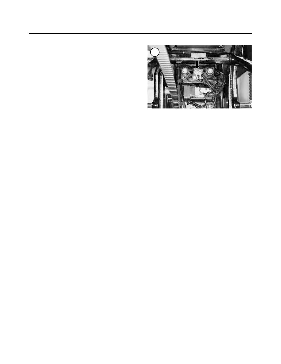
Do not consider a tripped circuit breaker a minor an-
noyance; it indicates something is wrong in the electrical
system and must be corrected immediately.
Replacement
The circuit breaker is located on the electrical pan for-
ward of the rear wheel.
1. Remove the seat as described in Chapter Fourteen.
2. Turn the ignition switch OFF.
3. Disconnect the negative battery cable as described in
this chapter.
4. Refer to
Electrical Panel
in this chapter to gain access
to the circuit breaker.
NOTE
Record the wire’s colors and the terminal to
which they are connected. The wires must be
reinstalled onto the correct terminal.
5. Remove the nuts and wire connections at the circuit
breaker (Figure 145).
6. Remove the circuit breaker from the mounting bracket
on the electrical panel.
7. Install the circuit breaker by reversing these steps.
ELECTRICAL CONNECTOR SERVICE
A variety of electrical connectors are used throughout
the electrical system. The following procedures are for
disassembly of the connector in order to replace an indi-
vidual electrical wire in the connector.
These connectors are designed for a superior seal to
prevent dirt and moisture from entering the connector and
damaging a pin connector.
Deutsch Electrical Connectors Socket Terminal
Removal/Installation
This procedure shows how to remove and install the
socket terminals from the socket housing connector half.
This procedure is shown on a 12-pin Duetsch connector
and is the same for two-, three-, four- and six-pin Duetsch
connectors.
Refer to Figure 146 and Figure 147.
1. Remove the seat as described in Chapter Fourteen.
NOTE
Always disarm the optional TSSM security
system prior to disconnecting the battery or
the siren will sound.
2. Disconnect the negative battery cable as described in
this chapter.
3. Disconnect the connector housing.
4. Remove the secondary locking wedge (7, Figure 147)
as follows:
a. Locate the secondary locking wedge in Figure 146
or Figure 147.
b. Insert a wide-blade screwdriver between the socket
housing and the locking wedge. Turn the screw-
driver 90
!
to force the wedge up (Figure 148).
c. Remove the secondary locking wedge (7, Figure
147).
5. Lightly press the terminal latches inside the socket
housing and remove the socket terminal (14, Figure 147)
through the holes in the rear wire seal.
6. Repeat Step 5 for each socket terminal.
7. If necessary, remove the wire seal (12, Figure 147).
8. Install the wire seal (12, Figure 147) into the socket
housing if it was removed.
9. Hold onto the socket housing and insert the socket ter-
minals (14, Figure 147) through the holes in the wire seal
so they enter their correct chamber hole. Continue until
the socket terminal locks into place. Then lightly tug on
the wire to make sure it is locked into place.
10. Set the internal seal (8, Figure 147) onto the socket
housing if it was removed.
NOTE
With the exception of the three-pin Duetsch
connector, all of the secondary locking
wedges are symmetrical. When assembling
the three-pin connector, install the connec-
tor so the arrow on the secondary locking
wedge is pointing toward the external latch
as shown in
Figure 149
.
NOTE
If the secondary locking wedge does not
slide into position easily, one or more of the
370
CHAPTER EIGHT
145