Harley Davidson Softail 2000-2005. Service manual - page 34
 

  Главная      Harley Davidson     Harley Davidson Softail 2000-2005. Service manual


Search            copyright infringement  


Content      ..     32      33      34      35     ..


Harley Davidson Softail 2000-2005. Service manual - page 34


Rear Turn Signal Bulb Replacement

1. Remove the screws securing the lens and remove the
lens.
2. Push in on the bulb, rotate it and remove it.
3. Install a new bulb and lens.
4. Install the screws and tighten them securely. Do not
overtighten the screws as the lens may crack.

Taillight/Brake and License Plate Light Replacement
(FXSTD Models)

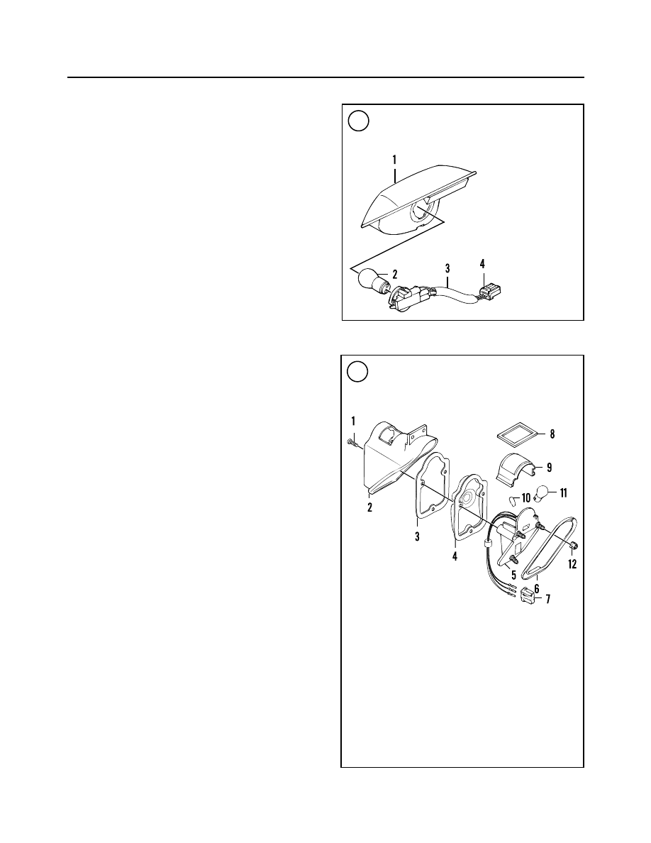
Refer to Figure 112.

1. Insert a small diameter screwdriver into the middle
hole in the license plate cover. Push in on the screwdriver
and release the internal clip.
2. Carefully pull the taillight/brake light assembly out
and away from the housing.
3A. To replace the taillight/brake light bulb, perform the
following:

a. Rotate the bulb housing and socket

counterclock-

wise

and pull straight out.

b. Rotate the bulb

counterclockwise

and pull straight

out of the socket.

c. Install a new bulb and rotate it

clockwise

into the

socket.

d. Rotate the bulb housing and socket

clockwise

and

push it straight in until it bottoms.

3B. To replace the license plate bulb, perform the following:

a. Rotate the bulb housing and socket

counterclock-

wise

. Pull it straight out and make sure the tabs clear

of the notches in the housing.

b. Pull the bulb straight out of the socket.
c. Install a new bulb and push it into the socket.
d. Align the socket tabs, push the socket into the hous-

ing and rotate it

clockwise

.

4. Correctly position the taillight/brake light assembly
routing the electrical wires to either side of the assembly.
5. Insert the top clip under the edge of the fender to lock it
into place.
6. Push the assembly toward the front of the motorcycle
and engage the lower clip with the lower edge of the bot-
tom opening in the fender.
7. Push down on the assembly until an audible click is
heard. Pull out on the assembly to make sure it is locked
into place in the housing.

Taillight/Brake Light Replacement
(FLSTS Models)

Refer to Figure 113.

1. Remove the three screws securing the lens.

354

CHAPTER EIGHT

112

TAILLIGHT/BRAKE LIGHT

(FXSTD MODELS)

1. Lens assembly
2. Bulb
3. Socket/wiring harness
4. Contact socket

113

TAILLIGHT/BRAKE LIGHT

(FLSTS MODELS)

1. Screw
2. Housing
3. Gasket
4. Lens
5. Base
6. Gasket
7. Socket housing
8. Gasket
9. Lens (license plate)

10. Bulb (license plate)
11. Bulb (taillight/brake light)
12. Nut

2. Pull the housing and lens off the base.
3. Rotate the bulb and remove it from the socket assembly.
4. Install a new bulb, then install the housing and lens
onto the base.
5. Install the screws and tighten them securely.
6. Replace the light base as follows:

a. Remove both seats as described in Chapter Fourteen.
b. Disconnect the negative battery cable as described

in this chapter.

c. Remove the right side saddlebag as described in

Chapter Fourteen.

d. Disconnect the light base three-pin Amp multi-lock

connector. Refer to

Electrical Connector Service

at

the end of this chapter.

e. From underneath the rear fender, disconnect the

wiring harness from the backside of the fender.
Note the harness routing prior to disconnect it from
the fender clips.

f. Remove the three nuts securing the base to the un-

derside of the rear fender.

g. Carefully pull the light base and rubber grommets

from the rear fender. Pull the wiring harness out of
the rear fender and remove the light base assembly.

h. Install by reversing these steps.

Taillight/Brake Light Replacement
(All Models Except FLSTS and FXSTD)

Refer to Figure 114.

1. Remove the screws securing the lens (Figure 115).
2. Pull the lens off the base and disconnect the four-pin
electrical connector.
3. Pull the bulb/socket assembly (Figure 116) out from
the backside of the lens.
4. Rotate the bulb and remove it from the socket assem-
bly (Figure 117).
5. Install a new bulb, then install the socket assembly into
the lens.

ELECTRICAL SYSTEM

355

8

114

TAILLIGHT/BRAKE LIGHT

(ALL MODELS EXCEPT

FLSTS & FXSTD)

1. Screw
2. Lens
3. Bulb
4. Socket/harness
5. Screw
6. Circuit board/cover assembly
7. Base
8. Cage nut

116

115

117

6. Connect the electrical connector, and install the lens
onto the base.

7. Install the screws and tighten them securely. Do not
overtighten the screws as the lens may crack.

8. Replace the base as follows:

a. From underneath the rear fender, disconnect the

wiring harness from the backside of the base.

b. Remove the screw securing the printed circuit board

and base to the rear fender.

c. Remove the base.

d. Install by reversing these steps.

Front Fender Tip Light Replacement
(FLSTS Models)

Refer to Figure 118.

1. Remove the rear screw securing the light cover.

2. From underneath the front fender, secure the crimp nut
and loosen remove the front screw securing the light cover.

3. Remove the light cover.

4. Carefully pull the bulb straight back out of the socket.

5. Install a new bulb, then install the light cover. Make
sure it is seated correctly on the mounting pad.

6. Install the screws and tighten them securely.

7. Replace the light lens/socket assembly as follows:

a. Remove the light cover as previously described.

b. Remove both seats as described in Chapter Fourteen.

c. Disconnect the negative battery cable as described

in this chapter.

d. Remove the fuel tank as described in Chapter

Seven.

e. Disconnect the light lens/socket assembly two-pin

Amp multi-lock connector. Refer to

Electrical Con-

nector Service

at the end of this chapter.

f. Disconnect or cut all straps securing the wiring har-

ness to the frame and front fender.

g. From underneath the front fender, disconnect the

wiring harness from the backside of the fender.
Note the harness routing prior to disconnect it from
the fender clips.

h. Use a long screwdriver and carefully pry the metal

clips away from the fender.

i. Carefully pull the lens/socket and rubber grommet

from the front fender. Pull the wiring harness out of
the front fender and remove the light base assembly.

j. Install by reversing these steps.

SWITCHES

Testing

Test switches for continuity by using an ohmmeter (see

Chapter One) or a self-powered test light at the switch
connector plug and operating the switch in each of its op-
erating positions. Compare the results with the switch op-
erating diagrams included in the wiring diagrams located
at the end of the manual.

For example, Figure 119 shows the continuity diagram

for a typical ignition switch. It shows which terminals
should show continuity when the switch is in a given posi-
tion. When the ignition switch is in the IGNITION posi-
tion, there should be continuity between the red/black, red
and red/gray terminals. Note the line on the continuity dia-
gram. An ohmmeter connected between these three termi-
nals should indicate little or no resistance, or a test light
should light. When the starter switch is OFF, there should be
no continuity between the same terminals. Replace the
switch or button if it does not perform properly.

When testing the switches, note the following:

1. Check the battery as described under

Battery

in this

chapter. Charge or replace the battery if necessary.
2. Disconnect the negative battery cable as described in
this chapter before checking the continuity of any switch.
3. Detach all connectors located between the switch and
the electrical circuit.

CAUTION

Do not attempt to start the engine with the
battery disconnected.

4. When separating two connectors, pull on the connector
housings and not the wires.

356

CHAPTER EIGHT

118

FENDER LAMP

(FLSTS MODELS)

1. Screw
2. Lamp
3. Screw
4. Cover
5. Lens/socket

assembly

6. Contact socket
7. Mounting pad
8. Nut

5. After locating a defective circuit, check the connectors
to make sure they are clean and properly connected.
Check all wires going into a connector housing to make
sure each wire is positioned properly and the wire end is
not loose.
6. To reconnect connectors properly, push them together
until they click or snap into place.

Handlebar Switches

Left handlebar switch description

The left side handlebar switch housing (Figure 120) is

equipped with the following switches:

1. Headlight dimmer.

2. Horn.

3. Left side turn signal.

Right handlebar switch description

The right side handlebar switch housing (Figure 121) is

equipped with the following switches:

1. Engine stop/run.

2. Start.

3. Right side turn signal.

4. Front brake light.

ELECTRICAL SYSTEM

357

8

Switch

Position

Red/black

Red

Red/gray

Off

!

Accessory

!

!

Ignition

!

!

!

119

IGNITION SWITCH (TYPICAL)

120

HANDLEBAR SWITCH

(LEFT SIDE)

1. Upper housing
2. Screw
3. Switch—

headlight dimmer
and horn

4. Electrical connector
5. Switch—left turn

signal

6. Lower housing
7. Screw

121

HANDLEBAR SWITCH

(RIGHT SIDE)

1. Upper housing
2. Screw
3. Switch—engine

stop and
engine start

4. Clip (2002-on)
5. Switch—stop lamp
6. Spring clip
7. Electrical connector
8. Switch—right

turn signal

9. Lower housing

10. Screw

Handlebar switch replacement

1. Remove the screws securing the left side switch hous-
ing (Figure 122) to the handlebar. Then carefully separate
the switch housing to access the defective switch (Figure
123
).
2. Remove the screws securing the right side switch
housing (Figure 124) to the handlebar. Then carefully
separate the switch housing to access the defective switch
(Figure 125).

NOTE

To service the front brake light switch, refer
to

Front Brake Light Switch Replacement

in this chapter.

3A. On models without splices, remove the screw and
bracket.
3B. On models with splices, remove the cable strap.
4. Pull the switch(es) out of the housing.
5. Cut the switch wire(s) from the defective switch(es).
6. Slip a piece of heat shrink tubing over each wire cut in
Step 2.
7. Solder the wire end(s) to the new switch. Then shrink
the tubing over the wire(s).
8. Install the switch by reversing these steps. Note the
following:

a. When clamping the switch housing onto the handle-

bar, check the wiring harness routing position to
make sure it is not pinched between the housing and
handlebar.

b. To install the right side switch housing, refer to

Throttle and Idle Cable Replacement

in Chapter

Seven.

WARNING

Do not ride the motorcycle until the throttle
cables are properly adjusted. Also, the ca-
bles must not catch or pull when the handle-
bars are turned. Improper cable routing and

358

CHAPTER EIGHT

122

123

124

Upper housing with splices

Upper housing without splices

adjustment can cause the throttle to stick
open. This could cause loss of control.

Front Brake Light Switch Replacement

The front brake light switch (Figure 126) is mounted in

the right side switch lower housing.
1. Separate the right side switch housing as described un-
der

Handlebar Switch Replacement

in this chapter.

2. If the wedge between the switch and the switch hous-
ing is still in place, remove it.
3. Cut the switch wires 1.0 in. (25.4 mm) from the defec-
tive switch.
4. While depressing the switch plunger, slowly rotate the
switch upward, rocking it slightly, and remove it from the
switch housing.
5. Check that the plunger is square in the bore and that the
boot is not compressed, collapsed or torn. Work the
plunger in and out until the boot is fully extended.
6. Slip a piece of heat shrink tubing over each wire cut in
Step 3.
7. Solder the wire ends to the new switch. Then shrink the
tubing over the wires.
8. Install the switch by reversing these steps. Note the
following:

a. When clamping the switch housing onto the handle-

bar, check the wiring harness routing position to
make sure it is not pinched between the housing and
handlebar.

b. To install the right side switch housing, refer to

Throttle and Idle Cable Replacement

in Chapter

Seven.

WARNING

Do not ride the motorcycle until the throttle
cables are properly adjusted. The cables
must not catch or pull when the handlebars
are turned. Improper cable routing and ad-
justment can cause the throttle to stick open.
This could cause a loss of control. Recheck
the work before riding the motorcycle.

Ignition/Light Switch Removal/Installation

Refer to Figure 127 and Figure 128.

1. Remove the fuel tank console as described under

Fuel

Tank Console

in Chapter Seven.

2. Turn the fuel tank console over onto towels on the
workbench.
3. Remove the four screws securing the ignition switch
(Figure 129) to the bottom surface of the fuel tank console.
4. Remove the ignition switch.

ELECTRICAL SYSTEM

359

8

125

126

Upper housing without splices

Upper housing with splices

5. Install the new ignition switch with the electrical con-
nector terminal facing toward the rear of the fuel console.
Tighten the screws securely.
6. Install the fuel tank console as described under

Fuel

Tank Console

in Chapter Seven.

Oil Pressure Switch

Operation

The oil pressure switch is located on the front right side

of the crankcase.

A pressure-actuated diaphragm-type oil pressure switch

is used. When the oil pressure is low or when oil is not cir-
culating through a running engine, spring tension inside
the switch, holds the switch contacts closed. This com-
pletes the signal light circuit and causes the low oil pres-
sure indicator lamp to light.

The oil pressure signal light should turn on when any of

the following occurs:
1. The ignition switch is turned on prior to starting the en-
gine.
2. The engine speed idle is below of 950-1050 rpm.
3. The engine is operating with low oil pressure.
4. Oil is not circulating through the running engine.

NOTE

The oil pressure indicator light may not
come on when the ignition switch is turned
off then back on immediately. This is due to
the oil pressure retained in the oil filter
housing. Test the electrical part of the oil
pressure switch in the following steps. If the
oil pressure switch, indicator lamp and re-
lated wiring are in good condition, inspect
the lubrication system as described in
Chapter Two.

Testing/replacement

1. Remove the rubber boot (A, Figure 130) and discon-
nect the electrical connector from the switch.
2. Turn the ignition switch ON.
3. Ground the switch wire to the engine.
4. The low oil pressure indicator lamp on the instrument
panel should light.
5. If the indicator lamp does not light, check for a defec-
tive indicator lamp, and inspect all wiring between the
switch, or sender, and the indicator lamp.
6A. If the oil pressure warning light operates properly, at-
tach the electrical connector to the pressure switch. Make

360

CHAPTER EIGHT

127

FUEL TANK CONSOLE (FXSTD MODELS)

1. Trim insert
2. Seal
3. Speedometer
4. Reset switch boot
5. Reset switch
6. Indicator lamp bezel
7. Screw
8. Fuel tank console
9. T25 Torx screw

10. Washer
11. Screw
12. Mounting bracket
13. Trim
14. Ignition switch
15. Screw
16. Back lamp
17. Indicator lamp assembly

sure the connection is tight and free of oil. On models with
a switch, slide the rubber boot back into position.
6B. If the warning light remains on when the engine is
running, shut the engine off. Check the engine lubrication
system as described in Chapter Two.
7. To replace the switch, perform the following:

a. Use a 1-1/16 in. open-end wrench and unscrew the

switch (B, Figure 130) from the engine.

NOTE

If the original switch is going to be reinstalled,
perform sub step b. A new switch already has
a sealant contact path on the threads. Do not
add any additional sealant to a new switch.

b. If reinstalling the original switch, apply Teflon Loctite

pipe sealant to the switch threads prior to installation.

c. Install the switch and tighten it to 96-144 in.-lb.

(11-16 N•m).

d. Test the new switch as described in Steps 1-4.

Neutral Indicator Switch Replacement

The neutral indicator switch is located on the transmis-

sion top cover. The neutral indicator light on the instru-

ELECTRICAL SYSTEM

361

8

128

FUEL TANK CONSOLE (ALL MODELS EXCEPT FSXTD)

1. Speedometer
2. Seal ring
3. Fuel tank console
4. Back lamp
5. Indicator lamp bezel
6. Acorn nut
7. Washer
8. Name plate
9. Trim

10. Bolt
11. Indicator lamp assembly
12. Ignition switch
13. Screw
14. Trim
15. Ignition key
16. Odometer reset switch
17. Rubber boot

130

129

ment panel should light when the ignition is turned ON
and the transmission is in NEUTRAL.
1. Disconnect the electrical connector from the neutral
indicator switch.
2. Turn the ignition switch ON.
3. Ground the neutral indicator switch wire to the trans-
mission case.
4. If the neutral indicator lamp lights, the neutral switch is
defective. Replace the neutral indicator switch and retest.
5. If the neutral indicator lamp does not light, check for a
defective indicator lamp, faulty wiring or a loose or cor-
roded connection.

NOTE

The electrical connector can be attached to
either stud on the switch.

6A. If the neutral switch operates correctly, attach the
electrical connector to the neutral switch. Make sure the
connection is tight and free of oil.
6B. If the neutral switch is defective, replace the neutral
indicator switch.
7. To replace the old switch, perform the following:

a. Shift the transmission into NEUTRAL.
b. Disconnect the oil tank feed line (A, Figure 131) as

described in Chapter Four.

c. Unscrew and remove the old switch and O-ring (B,

Figure 131) from the transmission top cover.

d. Apply clean transmission oil to the

new

O-ring seal.

e. Install the new switch and tighten it to 120-180

in.-lb. (14-20 N•m).

Rear Brake Light Switch Testing/Replacement

A hydraulic, normally-open rear brake light switch is

used on all models. The rear brake light is attached to the
rear brake caliper brake hose assembly. When the rear
brake pedal is applied, hydraulic pressure closes the
switch contacts, providing a ground path so the rear brake
lamp comes on. If the rear brake lamp does not come on,
perform the following:

NOTE

Removal of the exhaust system is not neces-
sary, but it provides additional work room if
necessary for this procedure.

1. If necessary, remove the exhaust system from the right
side as described in Chapter Seven.
2. Turn the ignition switch OFF.
3. Disconnect the electrical connector (A, Figure 132)
from the switch.

4. Connect an ohmmeter between the switch terminals.
Check the following:

a. Apply the rear brake pedal. There should be conti-

nuity.

b. Release the rear brake pedal. There should be no

continuity.

c. If the switch fails either of these tests, replace the

switch.

5. Place a drip pan under the switch, as some brake fluid
will drain out when the switch is removed.

362

CHAPTER EIGHT

131

132

133

6. Loosen and remove the switch (B, Figure 132) from
the fitting on the rear brake line.
7. Thread the new switch into the fitting and tighten it to
96-120 in.-lb. (11-14 N•m).
8. Reconnect the switch electrical connectors.
9. Bleed the rear brake as described in Chapter Thirteen.
10. Check the rear brake light with the ignition switch
turned ON and the rear brake applied.

HORN

Testing

1. Remove the seat.
2. Refer to the following procedure and partially remove
the horn to gain access to the electrical connector.
3. Disconnect the electrical connector (Figure 133) from
the backside of the horn.
4. Connect a positive voltmeter test lead to the yel-
low/black electrical connector and the negative test lead
to ground.

5. Turn the ignition switch to the ON position.
6. Press the horn button. If battery voltage is present, the
horn is faulty or is not grounded properly. If there is no
battery voltage, either the horn switch or the horn wiring
is faulty.
7. Replace the horn or horn switch as necessary.

Replacement

1. Remove the seat as described in Chapter Fourteen.
2. Disconnect the negative battery cable as described in
this chapter.
3A. On FLSTS models, remove the screws securing the
horn assembly to the passing lamp mounting bracket.
3B. On all models except FLSTS, remove the acorn nut
and washer (A, Figure 134) securing the horn assembly
bracket (B) to the engine mounting bracket.
4. Move the horn assembly to the frame and engine, and
disconnect the electrical connector (Figure 133) from the
horn spade terminals.
5. Remove the large nut securing the horn to the mount-
ing bracket, and remove the horn.
6. Install the horn by reversing these removal steps. Note
the following:

a. Make sure the electrical connectors and horn spade

terminals are free of corrosion.

b. Connect the wires to the horn’s top spade terminals.
c. Make sure the horn operates correctly.

ELECTRICAL PANEL

The electrical panel is located in front of the rear wheel

behind the rear fender inner panel. The panel assembly
houses the main circuit breaker, the vehicle speed sensor,
turn signal module (2000 models) or turn signal security
module (2001-on models) and security siren connector
(models so equipped). Refer to Figure 135.

To gain access to the electrical panel, perform the fol-

lowing:
1. Remove the seat.

NOTE

Always disarm the optional TSSM security
system prior to disconnecting the battery or
the siren will sound.

2. Disconnect the negative battery cable as described in
this chapter.

NOTE

The rear wheel can remain in place, but re-
moval allows easier access to the components.

ELECTRICAL SYSTEM

363

8

135

134

1. Speedometer sensor
2. TSM or TSSM

3. Master circuit breaker
4. Optional siren

3. Remove the rear wheel as described in Chapter Nine.

4. Remove the two bolts (A, Figure 136) securing the
rear fender inner panel.

5. Move the inner panel up, unhook it from the upper
mounting tab (B, Figure 136) and remove the inner panel.

6. Install the inner panel and hook it onto the upper mount-
ing tab. Pull down and make sure it is attached correctly.

7. Install the two lower bolts and tighten securely.

8. Install the rear wheel as described in Chapter Nine.

9. Connect the negative battery cable.

10. Install the seat.

TURN SIGNAL MODULE (2000 MODELS)

The turn signal module (TSM) is an electronic micro-

processor that controls the turn signals and the four-way
hazard flasher. The turn signal module receives its infor-
mation from the speedometer and turn signal switches.

The turn signal module is located on the electrical panel

located in front of the rear wheel.

If the following tests do not solve or confirm the prob-

lem, refer TSM testing to a Harley-Davidson dealership.

Operation

Refer to Figure 137.

1. When the left turn signal switch is pressed, a momen-
tary 12 VDC pulse sent to Pin No. 8 (input) on the TSM
module. The module responds to this signal by sending a
series of 12 VDC pulses to Pin No. 4 (output) to flash the
left front and rear turn signal lamps.

2. The TSM module then monitors the number of motor-
cycle sensor pulses sent from the speedometer sending
unit to Pin No. 5. These pulses indicate the distance the
motorcycle has traveled. When the number of speedome-
ter pulses is equal to the quantity preset in the module pro-
gram, the turn signal is cancelled.

NOTE

If the turn signal switch is pressed and held
in, the turn signal will flash indefinitely until
the switch is released.

3. When the right turn signal switch is pressed, a momen-
tary 12 VDC pulse sent to Pin No. 7 (input) on the TSM
module and an output signal at Pin No. 3 (output). The re-
maining signal process is identical to the left turn signal
operation.

Preliminary Troubleshooting

If one of the turn signals does not flash perform the fol-

lowing:
1. Remove the lens and check for a defective bulb(s). Re-
place the bulb(s) if necessary.
2. If the bulb(s) is good, check for one of the following
problems:

a. Check the bulb socket contacts for corrosion. Clean

the contacts and recheck. If there is a problem with
corrosion building on the contacts, wipe the con-
tacts with a dielectric grease before reinstalling the
bulb.

b. Check for a broken wire within the circuit. Repair

the wire(s) or connector(s).

c. Check for a loose bulb socket where it is staked to

the housing. If the bulb socket is loose, replace the
light assembly.

d. Check for a poor ground connection. If the ground

is poor, clean the ground mounting area or replace
damaged ground wire(s), as required.

e. Stuck turn signal button.

3. Remove the TSM as described in this chapter.
4. Disconnect the electrical connector from the TSM.
5. Check the electrical connectors in the TSM and in the
wiring harness for corrosion. Clean off if necessary.

Distance Test

The turn signal module (TSM) recognizes four different

speed ranges and uses these distances to activate the can-
cellation action. Refer to the speed ranges listed in Table
6
.
1. Ride the motorcycle at the mid-point of speed range
No. 1.
2. Press and release the right turn button and closely
check the motorcycle speed and the odometer at the time

364

CHAPTER EIGHT

136

the button is released and the time the turn signal is can-
celled.
3. Repeat Step 1 and Step 2 for right and left turns at the
midpoint of speed ranges No. 2 through No. 4.
4. If the distances observed in Steps 1-3 are not correct,
check the following steps:

a. Check the TSM ground connection and module pin

connections for corrosion.

b. Check all lamps and lamp connections.
c. Check the motorcycle speed sensor connections and

ground for corrosion.

Time Test

This is an alternate test to the speed/distance test, to

check if the TSM module is operating correctly. Measure
the turn signal ON time at the four indicated constant
speeds listed in Table 7.

If the TSM fails this test, replace the TSM and repeat

with a good module.

Rider Preference Setting

If the rider desires the turn signals to flash for a longer

or shorter distance that the pre-set time, perform the fol-
lowing:
1. Longer distance cycle—hold the turn signal longer and
release it closer to the turning point.
2. Shorter distance cycle—press the button a second time
to cancel the turn signals.

Turn Signal Module (TSM)
Removal/Installation

Refer to Figure 135.

1. Remove the seat as described in Chapter Fourteen.
2. Disconnect the negative battery cable as described in
this chapter.
3. Turn the ignition switch OFF.
4. Refer to

Electrical Panel

in this chapter to gain access

to the TSM.

ELECTRICAL SYSTEM

365

8

137

TURN SIGNAL MODULE (TSM) (2000)

1. Module ground to motorcycle
2. 12 VDC input from accessory

circuit breaker

3. Pulsed 12 VDC for flashing

right signal lights

4. Pulsed 12 VDC for flashing

left signal lights

5. Speed sensor input from

speedometer

6. Not used
7. 12 VDC input from right side

handlebar switch

8. 12 VDC input from left side

handlebar switch

Speedometer

Module

Power

Left turn
signal
lights

Right turn
signal
lights

Left turn
signal
switch

Right turn
signal
switch

W/V

W/BN

W/G

B

V

BN

O/W

5. Disconnect the eight-pin Deutsch connector from the
module.
6. Remove the bolt securing the module to the electrical
panel.
7. Install the module by reversing these removal steps
while noting the following:

a. Make sure the electrical connectors are free of cor-

rosion.

b. Tighten the bolt securely. Be sure to install the rub-

ber washer.

c. Make sure the turn signal and flasher systems work

properly.

TURN SIGNAL MODULE AND

TURN SIGNAL/SECURITY MODULE

(2001-ON MODELS)

The turn signal module (TSM) is an electronic micro-

processor that controls the turn signals and four-way haz-
ard flasher. The turn signal module receives its
information from the speedometer and turn signal
switches. On models equipped with a security system
(TSSM), it is incorporated into the TSM module. The
bank angle sensor (BAS) provides motorcycle movement
signals to the module. TSM and TSSM modules are not
interchangeable.

The turn signal module, TSM or TSSM, is located on

the electrical panel located in front of the rear wheel.

When there is a problem with either system, a diagnos-

tic fault code(s) is set. The TSM or TSSM can only be
tested with Harley-Davidson diagnostic equipment. The
following information describes how the systems are de-
signed to operate. If any portion of the module is inopera-
tive, refer the testing to a Harley-Davidson dealership.

Turn Signal Operation

Automatic cancellation

NOTE

The TSM/TSSM will not cancel the signal
before the turn is actually completed.

1. When the turn signal button is pressed and released,
the system begins a 20 count. As long as the motorcycle is
moving above 7 MPH (11 KPH) and the ISM does not re-
ceive any additional input, the turn signals will cancel af-
ter 20 bulb flashes.
2. If the motorcycle’s speed drops to 7 MPH (11 KPH) or
less, the turn signals will continue to flash. The count re-
sumes when the motorcycle reaches 8 MPH (13 KPH) and

the turn signal will cancel when the total count equals 20
bulb flashes.
3. The turn signals will cancel two seconds after a turn of
45

!

or more is completed.

Manual cancellation

1. After the turn signal button is pressed and released, the
system begins a 20 count. To cancel the turn signal, press
the turn signal button a second time.
2. If the turn direction is changed, press the opposite turn
signal button. The primary signal is cancelled and the op-
posite turn signal will flash.

Four-way flashing

1. Turn the ignition key to the ON position. On models so
equipped, disarm the security system. Press the right and
left turn signal buttons at the same time. All four turn sig-
nals will flash at the same time.
2. On models with the security system, the system can be
armed so all four signals flash for up to two hours. Turn
the ignition key to the OFF position and arm the security
system. Press both the right and left turn signal buttons at
the same time.
3. To cancel the four-way flashing, disarm the security
system, on models so equipped, and press both the right
and left turn signal buttons at the same time.

Bank angle sensor (BAS)

The bank angle sensor automatically shuts off the engine

if the motorcycle tilts more than 45

!

for longer than one sec-

ond. The shutoff will occur even at a very slow speed.

To restart the motorcycle, return the motorcycle to ver-

tical. Turn the ignition key from OFF to ON, then restart
the engine.

366

CHAPTER EIGHT

138

Security System (TSSM) Operation

If a theft attempt is detected and the TSSM is in opera-

tion, it immobilizes the starting and ignition systems. It
also flashes the right and left turn signals alternately and
sounds the siren, if so equipped. The following conditions
activate the armed security system:

1. Small motorcycle movement—the turn signals flash
three times and the optional siren chirps once. If the mo-
torcycle is not returned to its original position, the warn-
ings will reactivate after four seconds. This cycle will
repeat a maximum of 255 times.

2. Large motorcycle movement—the system will acti-
vate for 30 seconds, then turn off. If the motorcycle is not
returned to its original position, the warnings will reacti-
vate after ten seconds. This cycle may repeat a maximum
of ten times.

3. Tampering of the security lamp circuit—system acti-
vates for 30 seconds. The cycle will repeat for each tam-
pering incident.

4. A battery ground or ground disconnect has occurred
while the system is armed—the siren will sound, if so
equipped, but the turn signals will not flash.

NOTE

Always disarm the optional TSSM prior to
disconnecting the battery or the siren will
sound. If the TSSM is in auto-alarming
mode, disarm the system with two clicks of
the key fob, and disconnect the battery or re-
move the TSSM fuse before the 30 second
arming period expires.

Turn Signal Security Module (TSSM)
Removal/Installation

1. Remove the seat as described in Chapter Fourteen.

2. Turn the ignition switch OFF.

3. Disconnect the negative battery cable as described in
this chapter.
4. Refer to

Electrical Panel

in this chapter to gain access

to the TSSM.
5. Carefully pull the TSSM (Figure 138) from the
bracket on the electrical panel.
6. Disconnect the twelve-pin electrical Deutsch connec-
tor from the module and remove the module.
7. Install the module by reversing these removal steps.
Note the following:

a. Make sure the electrical connector is free of mois-

ture.

b. Make sure the protrusion on the module is secure in

the hole in the electrical panel bracket.

c. Make sure the turn signal and flasher systems work

properly.

SPEEDOMETER SPEED SENSOR

All models are equipped with an electronic speedome-

ter assembly that consists of the speedometer, speed sen-
sor and function switch.

The speed sensor mounts on top of the transmission

housing, directly over fourth gear.

Performance Check

The Harley-Davidson Speedometer Tester is required

to check the performance of the speedometer.

NOTE

This test cannot be used to verify the cali-
bration of the speedometer and will not ver-
ify the speedometer’s function for legal
proceedings. The test will verifies speedom-
eter function for service diagnosis or repair,
and verifies if the speedometer requires re-
placement.

Speedometer Speed Sensor
Removal/Installation

The speedometer speed sensor mounts on top of the

transmission case.
1. Remove the seat as described in Chapter Fourteen.
2. Disconnect the negative battery cable as described in
this chapter.
3. Remove the Allen screw and remove the speed sensor
(Figure 139) from the transmission case.
4. Disconnect the three-pin Mini-Deutsch connector con-
taining one red, one black and one white wire.

ELECTRICAL SYSTEM

367

8

139

5. Carefully pull the electrical connector out from under
the frame crossmember. Disconnect the secondary locks on
the Mini-Deutsch connector and disconnect the connector.
6. Tie a piece of string to the electrical connector. Tie the
other end of the string to the frame crossmember.
7. Carefully pull the wiring harness and connector out of
the frame on the right side. If the wire is tight or stuck, do
not force it. If necessary, make a drawing of the wire rout-
ing through the frame. It is easy to forget the routing path
after removing the wire.
8. Untie the string from the wiring harness.
9. Installation is the reverse of removal. Note the follow-
ing:

a. Tie the string to the wiring harness and connector.
b. Carefully pull the string and the wiring harness and

connector through the right side of the frame into
position under the seat. Untie and remove the string.

c. Apply a light coat of dielectric compound to the

electrical connector(s) prior to installing them.

d. Apply clean engine oil to the

new

O-ring on the

speedometer sensor prior to installation. Install the
sensor and tighten the Allen screw to 84-108 in.-lb
(10-12 N•m).

STARTER RELAY SWITCH REPLACEMENT

The starter relay switch is mounted under the fuse cover

on the left side of the frame.
1. Remove the seat as described in Chapter Fourteen.
2. Disconnect the negative battery cable as described in
this chapter.
3. Pull straight up and remove the fuse block cover (Fig-
ure 140
).
4. Unplug and remove the starter relay switch (A, Figure
141
) from the rear fuse block.
5. Install by reversing these steps.

SPEEDOMETER AND INDICATOR LIGHTS

Removal/Installation

Refer to Figure 127 and Figure 128.

1. Remove the seat.

NOTE

Always disarm the optional TSSM security
system prior to disconnecting the battery or
the siren will sound.

2. Disconnect the negative battery cable as described in
this chapter.

3. Remove the fuel tank console as described under

Fuel

Tank Console

in Chapter Seven.

4. Turn the fuel tank console over onto towels on the
workbench.
5. If still in place, remove the rubber boot from the reset
switch, then remove the nut securing the reset switch from
the side of the fuel tank console.
6A. On FSXST models, perform the following:

a. Unhook the retaining clip securing the indicator

lamp wire to the backside of the speedometer.

b. Disengage the clips securing the speedometer back

clamp to the fuel tank console.

c. Remove the speedometer and back clamp from the

fuel tank console.

d. If necessary, disengage the clips securing the back

clamp to the speedometer and remove the back
clamp.

6B. On all models except FXSTD, perform the following:

a. Use a flat blade screwdriver and carefully pry be-

tween the three locking tabs on the back clamp (A,
Figure 142) and the speedometer. Raise the back
clamp, release it from the speedometer and remove
the back clamp.

b. Remove the speedometer (Figure 143) from the

fuel tank console.

368

CHAPTER EIGHT

140

141

c. Remove the gasket from the speedometer.

7. To remove the indictor light assembly (B, Figure 142),
depress the locking tabs and remove the light assembly
from the fuel tank console.

8. Installation is the reverse of removal.

FUSES

All models are equipped with a series of 15 amp fuses to

protect the electrical system. The number of fuses varies

depending on the model. Refer to the wiring diagrams at
the end of the manual.

The fuse panel is located under the seat, behind the bat-

tery. If there is an electrical failure, first check for a blown
fuse. A blown fuse has a break in the element.

Whenever a fuse blows, find the reason for the failure

before replacing the fuse. Usually, the trouble is a short
circuit in the wiring. This may be caused by worn-through
insulation or a disconnected wire shorted to ground.
Check the circuit that the fuse protects.

Replacement

1. Remove the seat as described in Chapter Fourteen.

NOTE

Always disarm the optional TSSM security
system prior to disconnecting the battery or
the siren will sound.

2. Disconnect the negative battery cable as described in
this chapter.
3. Pull straight up and remove the fuse block cover (Fig-
ure 140
).

NOTE

Fuse description and location is printed on
the fuse block cover (

Figure 144

).

4. Locate the blown fuse (B, Figure 141) and install a
new fuse with the

same

amperage.

NOTE

Always carry spare fuses.

CIRCUIT BREAKER

All models use a single 30 amp circuit breaker to pro-

tect the electrical circuits.

Whenever a failure occurs in any part of the electrical

system, the circuit breaker is self-resetting and will auto-
matically return power to the circuit when the electrical
fault is found and corrected.

CAUTION

If the electrical fault is not found and cor-
rected, the circuit breaker will cycle on and
off continuously. This will cause the motor-
cycle to run erratically.

Usually the problem causing a short circuit is in the wir-

ing connected to the circuit breaker.

Determine the circuits protected by the circuit breaker

by following the wiring diagrams at the end of the manual.

ELECTRICAL SYSTEM

369

8

143

144

142


Content      ..     32      33      34      35     ..