Harley Davidson Softail 2000-2005. Service manual - page 33
 

  Главная      Harley Davidson     Harley Davidson Softail 2000-2005. Service manual


Search            copyright infringement  


Content      ..     31      32      33      34     ..


Harley Davidson Softail 2000-2005. Service manual - page 33


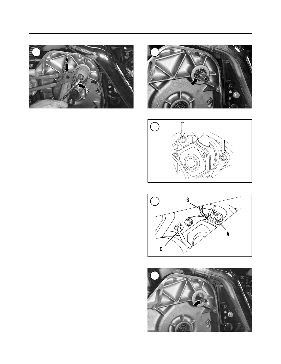
9. Remove the pinion gear (Figure 46) and spring from
the jackshaft.
10. Remove the jackshaft assembly and the coupling
from the inner housing.
11. Remove the starter mounting bolts and washers (Fig-
ure 47
).
12. Slide back the rubber boot, remove the nut (A, Figure
48
) and disconnect the positive cable from the starter ter-
minal. Note the location of the circuit breaker cable termi-
nal ring (B, Figure 48) under the front bolt and washer.
13. Disconnect the solenoid electrical connector (C, Fig-
ure 48
) from the starter.
14. Pull the starter straight out of the crankcase and re-
move it.
15. If necessary, service the starter as described in this
chapter.

Starter Installation

1. Install the starter into the crankcase. Push it in until it
bottoms.
2. Install the starter mounting bolts and washers (Figure
47
). Tighten the bolts to 13-20 ft.-lb. (18-27 N•m).
3. Connect the solenoid electrical connector (C, Figure
48
) onto the starter motor.
4. Install the circuit breaker cable terminal ring (B, Fig-
ure 48
) under the front bolt and washer.
5. Connect the positive cable onto the starter terminal and
install the nut (A, Figure 48). Tighten the nut securely,
then slide the rubber boot into position.
6. Install the cover onto the end of the starter and secure
with the bolt. Tighten the bolt securely.
7. Install the jackshaft (Figure 49) into the inner housing
if it was removed. Push it in until it stops.
8. Position the coupling with its counterbore facing to-
ward the jackshaft and install the coupling (Figure 50)
into the inner housing bushing.
9. Install the spring (Figure 51) onto the jackshaft.

338

CHAPTER EIGHT

45

46

47

48

49

10. Install the pinion gear (Figure 52) onto the jackshaft.

11. Push in on the pinion gear (A, Figure 53) and install
the bolt, lockplate and thrust washer (B) onto the
jackshaft.

12. Push the assembly on until it bottoms.

13. Align the lockplate tab with the thrust washer, then
insert the tab into the notch in the end of the jackshaft.

14. Screw the bolt into the starter shaft by hand.

15. Wrap the pinion gear with a cloth to protect the finish,
then secure it with pliers (A, Figure 45).

16. Tighten the starter jackshaft bolt (B, Figure 45) to
84-108 in.-lb. (9-12 N•m). Bend the outer lockplate tab
against the bolt head (Figure 44).

17. Ensure the components have been installed correctly
as follows:

a. Install the clutch shell onto the transmission

mainshaft.

b. With the starter not engaged, the pinion gear (A,

Figure 54) must not engage the clutch shell gear
(B).

c. To check for proper engagement, pull out on the

pinion gear and engage it with the clutch shell gear.
Then rotate the clutch shell in either direction and
make sure the pinion gear rotates with it.

d. If the engagement is incorrect, remove the clutch

shell and correct the problem.

e. Remove the clutch shell.

18. Install the oil tank as described in Chapter Four.

19. Install the cover and the bolt (B, Figure 43) onto the
end of the starter.

20. Install the oil tank (A, Figure 43) as described in
Chapter Four.

21. Install the primary drive outer cover as described in
Chapter Five.

22. Connect the negative battery cable.

23. Install the seat.

ELECTRICAL SYSTEM

339

8

51

52

53

54

50

Starter Disassembly

NOTE

If only the solenoid assembly requires ser-
vice, refer to

Starter Solenoid

in this chapter.

1. Clean all grease, dirt and carbon from the exterior of
the starter assembly (Figure 55).
2. Remove the two through bolts (Figure 56).
3. Remove the two drive housing Phillips screws (Figure
57
) and lockwashers.
4. Tap the drive housing and remove it from the starter as-
sembly (Figure 58).
5. Disconnect the C terminal field wire (A, Figure 59)
from the solenoid housing.
6. Separate the field coil (B, Figure 59) from the solenoid
housing (C).
7. Remove the end cap screws, washers and O-rings (A,
Figure 60). Then remove the end cap (B).
8. Pull the brush holder (A, Figure 61) away from the
commutator and remove the armature (B) from the field
coil assembly.
9. Remove the two field coil brushes from the brush
holder (Figure 62).

340

CHAPTER EIGHT

55

STARTER

1. Screw
2. Lockwasher
3. Drive housing
4. O-ring
5. Drive assembly
6. Idler gear bearing
7. Bearing rollers (5)
8. Idler gear
9. Drive spring

10. Clutch shaft
11. Ball
12. Return spring
13. Solenoid housing
14. Tab
15. Nut
16. Nut
17. Bearing
18. Armature
19. O-ring
20. Field coil assembly
21. Brushes
22. Brush springs
23. Brush holder
24. End cap
25. O-ring
26. Washer
27. Screw
28. Throughbolt

56

57

10. Clean all grease, dirt and carbon from the armature,
field coil assembly and end covers.

CAUTION

Be extremely careful when selecting a sol-
vent to clean the electrical components. Do
not immerse any of the wire windings in sol-
vent, because the insulation may be dam-
aged. Wipe the windings with a cloth lightly
moistened with solvent, then allow the solu-
tion to dry thoroughly.

11. To service the drive housing assembly, refer to

Drive

Housing

Disassembly/Inspection/Assembly

in

this

section.

12. To service the solenoid housing, refer to

Solenoid

Housing Disassembly/Inspection/Assembly

in this section.

Starter Inspection

1. Measure the length of each brush with a vernier caliper
(Figure 63). If the length is less than the minimum speci-

ELECTRICAL SYSTEM

341

8

58

59

60

61

62

63

fied in Table 3, replace all of the brushes as a set. See Fig-
ure 64 
for the field coil and Figure 65 for the brush holder.

NOTE

The field coil brushes (

Figure 64

) are sol-

dered into position. To replace them, un-
solder the brushes by heating their joints
with a soldering gun, then pull them out with
a pair of pliers. Position the new brushes
and solder them in place with rosin core sol-
der. Do not use acid core solder.

2. Inspect the commutator (A, Figure 66). The mica
should be below the surface of the copper commutator
segments (Figure 67). If the commutator bars are worn to
the same level as the mica insulation, have the commuta-
tor serviced by a dealership or electrical repair shop.

3. Inspect the commutator copper segments for discolor-
ation. If the commutator segments are rough, discolored
or worn, have the commutator serviced by a dealership or
electrical repair shop.

4. Measure the outer diameter of the commutator with a
vernier caliper (Figure 68). Replace the armature if it is
worn to the service limit in Table 3.

5. Use an ohmmeter to perform the following tests:

342

CHAPTER EIGHT

64

65

66

67

GOOD

WORN

68

69

a. Check for continuity between the commutator bars

(Figure 69); there should be continuity between
pairs of bars.

b. Check for continuity between any commutator bar

and the shaft (Figure 70). There should be no conti-
nuity.

c. If the unit fails either test, replace the armature.

6. Use an ohmmeter to perform the following tests:

a. Check for continuity between the starter cable ter-

minal and each field frame brush (Figure 71); there
should be continuity.

b. Check for continuity between the field frame hous-

ing and each field frame brush (Figure 72); there
should be no continuity.

c. If the unit fails either test, replace the field frame as-

sembly.

7. Use an ohmmeter to check for continuity between the
brush holder plate and each brush holder (Figure 73);
there should be no continuity. If the unit fails this test, re-
place the brush holder plate.
8. Service the armature bearings as follows:

a. Check the bearings (B, Figure 66) on the armature

shaft. Replace worn or damaged bearings.

b. Check the bearing bores in the end cover and sole-

noid housing. Replace the cover or housing if the
area is worn or cracked.

Starter Assembly

1. Assemble the drive housing as described in this chap-
ter if it was serviced.
2. Assemble the solenoid housing as described in this
chapter if it was serviced.
3. Lubricate the armature bearings (B, Figure 66) with
high-temperature grease.
4. Install two

new

O-rings onto the field coil shoulders

(Figure 74).

ELECTRICAL SYSTEM

343

8

70

71

72

Field frame

Starter terminal

Ohmmeter

Field frame

Ohmmeter

73

Insulated
brush
holders

Test leads

Brush holder plate

5. Install the two field coil brushes into the brush plate
holders (Figure 75).

6. Install the armature partway through the field coil as
shown in Figure 61. Then pull the brushes back and push the
armature forward, so when released, all of the brushes con-
tact the commutator as shown in Figure 76 and Figure 77.

7. Install the end cap (Figure 78) and the two screws,
washers and O-rings. Tighten the screws securely.

8. Align the field coil (A, Figure 79) with the solenoid
housing (B) and assemble both housings. Hold the assem-
bly together while installing the drive housing in Step 9.

9. Align the drive housing (Figure 80) with the field coil
and solenoid housing assembly, and install it. Install the
two drive housing screws and lockwashers (Figure 57).
Tighten them securely.

10. Install the two through bolts, washers and O-rings
(Figure 56). Tighten them securely.

11. Reconnect the C terminal field wire (C, Figure 79) at
the solenoid housing.

Drive Housing Disassembly/Inspection/Assembly

The drive housing was removed during starter disassembly.

344

CHAPTER EIGHT

74

75

76

77

78

79

1. Remove the return spring (A, Figure 81), ball, clutch
shaft (B) and drive spring (Figure 82) from the drive as-
sembly.
2. Remove the idler gear (Figure 83) from the drive
housing.
3. Remove the idler gear bearing and cage assembly (A,
Figure 84). There are five individual bearing rollers (Fig-
ure 85
).
4. Remove the drive assembly (B, Figure 84).
5. Replace the drive housing O-ring (Figure 86) if it is
worn or damaged. Lubricate the O-ring with high temper-
ature grease.

ELECTRICAL SYSTEM

345

8

80

81

82

83

84

85

86

6. Inspect the idler gear bearing and cage assembly (Fig-
ure 85
) for worn or damaged parts.

CAUTION

The drive assembly (

Figure 87

) is a sealed

unit. Do not clean or soak it in any type of
solvent.

7. Inspect the drive assembly and its bearings (Figure 87)
for worn or damaged parts. If the bearings are worn or
damaged, replace the drive assembly and bearings as a set.
8. Assemble the drive housing by reversing these steps.
Note the following:
9. Lubricate the following components with high temper-
ature grease.

a. Idler gear bearing and cage assembly (Figure 85).
b. Drive housing O-ring and shaft (Figure 86).

346

CHAPTER EIGHT

87

88

STARTER SOLENOID

1. Solenoid housing
2. Plunger
3. Gasket
4. Cover

5. Clip
6. Lockwasher
7. Bolt

89

90

91

92

c. Drive assembly (Figure 87).

d. Clutch shaft, drive spring, return spring and ball.

10. Install the idler gear bearing and cage assembly so the
open side of the cage (A, Figure 84) faces toward the so-
lenoid housing.

Solenoid Housing Disassembly/Inspection/Assembly

1. Remove the solenoid housing (Figure 88) as described
during starter disassembly.

2. Remove the screws, washers and clip securing the end
cover to the solenoid housing. Then remove the end cover
(Figure 89) and the gasket.

3. Remove the plunger assembly (Figure 90).

4. Inspect the plunger (Figure 91) for scoring, deep wear
marks or other damage.

5. Inspect the solenoid housing (Figure 92) for wear,
cracks or other damage.

6. The solenoid housing is a separate assembly and can-
not be serviced. If any part is defective, the solenoid hous-
ing must be replaced as an assembly.

7. Assemble the solenoid housing by reversing these steps.
Lubricate the solenoid plunger with high temperature grease.

LIGHTING SYSTEM

The lighting system consists of a headlight, passing lamps,

taillight/brake light combination and turn signals.

Always use the correct wattage bulb. The use of a larger

wattage bulb will give a dim light and a smaller wattage bulb
will burn out prematurely. Table 4 lists replacement bulb
specifications.

CAUTION

All models are equipped with a quartz-halo-
gen bulb. Do not touch the bulb glass.
Traces of oil on the bulb will drastically re-
duce the life of the bulb. Clean all traces of
oil from the bulb glass with a cloth moist-
ened in alcohol or lacquer thinner.

Headlight Bulb Replacement
(FXST and FXSTB Models)

Refer to Figure 93.

WARNING

If the headlight has just burned out or just
turned off, it will be hot. To avoid burned fin-
gers, allow the bulb to cool prior to removal.

ELECTRICAL SYSTEM

347

8

93

HEADLIGHT (FXST AND FXSTB MODELS)

1. Socket housing
2. Bolt
3. Washer
4. Mounting block
5. Washer
6. Lockwasher
7. Nut or acorn nut
8. Mounting plate
9. Lockwasher

10. Headlight case
11. Mounting ring
12. Connector boot
13. Clip
14. Headlight bulb
15. Headlight lens
16. Trim bezel
17. Screw
18. Nut

1. Loosen the screw (A, Figure 94) at the base of the trim
bezel (B) and remove the trim bezel from the headlamp
lens assembly.
2. Pull the lens assembly part way out of the headlight case.
3. Pull

straight out

on the electrical connector and dis-

connect it from the bulb (Figure 95). Remove the head-
light assembly.
4. Remove the connector cover (Figure 96) from the
back of the headlight lens. Check the rubber cover for
tears or deterioration; replace it if necessary.
5. Unhook the light bulb retaining clip (Figure 97) and
pivot it out of the way.
6. Remove and discard the blown bulb (Figure 98).
7. Align the tangs on the new bulb with the notches in the
headlight lens and install the bulb.
8. Securely hook the retaining clip onto the bulb (Figure
97
).
9. Install the connector cover (Figure 96) and make sure
it is correctly seated against the bulb and the retainer.
10. Correctly align the electrical plug terminals with the
bulb and connect the plug. Push it

straight on

until it bot-

toms on the bulb and the connector cover (Figure 95).
11. Check headlight operation.
12. Insert the lens into the headlight housing and seat it
correctly.
13. Install the trim bezel (B, Figure 94) into place and
tighten the screw (A) securely.
14. Check headlight adjustment as described in this chap-
ter.

Headlight Bulb Replacement
(FLSTS, FXSTD and FXSTS Models)

Refer to Figure 99.

WARNING

If the headlight has just burned out or just
turned off, it will be hot. To avoid burned

348

CHAPTER EIGHT

95

94

98

96

97

fingers, allow the bulb to cool prior to re-
moval.

1. Remove the screw at the base of the trim bezel and re-
move the trim bezel from the headlight lens assembly.

2. Pull the lens assembly part way out of the headlight
case.

3. Pull

straight out

on the electrical connector and dis-

connect it from the bulb. Remove the headlight assembly.

4. Remove the connector boot (Figure 96) from the back
of the headlight lens. Check the rubber boot for tears or
deterioration; replace it if necessary.

5. Squeeze the light bulb retaining clip (Figure 97) and
pivot it out of the way.

6. Remove and discard the blown bulb (Figure 98).

7. Align the tangs on the new bulb with the notches in the
headlight lens and install the bulb.

8. Securely hook the retaining clip onto the bulb.

ELECTRICAL SYSTEM

349

8

99

HEADLIGHT (FLTST, FXSTD AND FXSTS MODELS)

1. Socket housing
2. Terminal (female)
3. Terminal (spade)
4. Mounting bracket
5. Bolt
6. Washer
7. Acorn nut
8. Mounting bracket
9. Washer

10. Adapter ring
11. Gasket
12. Terminal (spade)

13. Socket housing
14. Pin housing
15. Connector boot
16. Clip
17. Headlight bulb
18. Headlight lens
19. Trim bezel
20. Screw
21. Headlight case

(FXSTS and FLSTS)

22. Headlight case (FXSTD)

9. Install the connector boot and make sure it is correctly
seated against the bulb and the retainer.
10. Correctly align the electrical plug terminals with the
bulb and connect the plug. Push it

straight on

until it bot-

toms on the bulb and the connector boot.
11. Check headlight operation.
12. Insert the lens into the headlight housing and seat it
correctly.
13. Install the trim bezel and screw. Tighten the screw se-
curely.
14. Check headlight adjustment as described in this chap-
ter.

Headlight Bulb Replacement
(FLSTC and FLSTF Models)

Refer to Figure 100.

WARNING

If the headlight has just burned out or just
turned off, it will be hot. To avoid burned

fingers, allow the headlight assembly to
cool prior to removal.

NOTE

On FLSTC and FLSTF HDI models, refer to

Headlight Bulb Replacement (FXST and
FXSTB Models)

in this chapter. These mod-

els are not equipped with a sealed beam
headlight assembly.

1. Remove the screw at the base of the trim bezel.

2. Carefully remove the trim bezel. Do not bend the two
top locating tabs at the top of the trim bezel.

3. Remove the three screws securing the retaining ring
and remove it while holding the headlight assembly in
place.

4. Pull the headlight assembly out of the headlight case.

5. Pull

straight out

on the electrical connector and dis-

connect it from the headlight assembly. Remove the head-
light assembly.

6. Remove and discard the blown headlight assembly.

350

CHAPTER EIGHT

100

HEADLIGHT (FLSTC AND FLSTF MODELS)

1. Headlight case
2. Sealed beam
3. Retaining ring
4. Screw
5. Trim bezel
6. Terminal (female)
7. Socket housing
8. Pin terminal

9. Bolt

10. Washer
11. Mounting block
12. Washer
13. Lockwasher
14. Nut or acorn nut
15. Lockwasher
16. Bolt

7. Correctly align the electrical plug terminals with the
bulb and connect the plug. Push it

straight on

until it bot-

toms on the headlight assembly.

8. Check headlight operation.

9. Insert the headlight assembly into the headlight case
and seat it correctly.

10. Install the retaining ring and three screws. Tighten
them securely.

11. Install the two top locating tabs on the trim bezel and
snap the trim bezel into place. Install the screw and tighten
it securely.

12. Check headlight adjustment as described in this chapter.

Headlight Adjustment

1. Park the motorcycle on a level surface approximately
25 ft. (7.6 m) from the wall.

2. Check tire inflation pressure. Readjust it if necessary,
as described in Chapter Three.

3A. On FLSTC and FLSTF models, draw a horizontal line
on the wall the same height as the center of the headlight
(Figure 101).

3B. On all models except FLSTC and FLSTF, draw a hori-
zontal line on the wall 35 in. (0.9 m) above the floor Fig-
ure 102
.

4. Have an assistant (with the same approximate weight
as the primary rider) sit on the seat.

5. Aim the headlight at the wall. Switch the headlight to
the HIGH beam. Point the front wheel straight ahead.

6. Turn the key switch to the IGNITION position.

7. Check the headlight beam alignment. The broad, flat
pattern of light (main beam of light) must be centered on
the horizontal line with an equal area of light above and
below line.

ELECTRICAL SYSTEM

351

8

101

HEADLIGHT ADJUSTMENT (FLSTC AND FLSTF MODELS)

25 ft.
(7.6 m)

102

HEADLIGHT ADJUSTMENT (ALL MODELS EXCEPT FLSTC AND FLSTF)

25 ft.
(7.6 m)

35 in.
(0.9 m)

8. Check the headlight beam lateral alignment. With the
headlight beam pointed straight ahead, there should be an
equal area of light to the left and right of center.
9. If the beam is incorrect, adjust it as follows:
10A. On FXSTS and FLSTS models, perform the follow-
ing:

a. Loosen the two vertical adjust bolts (Figure 103) to

move the headlight up and down. Tighten the bolts
to the specification in Table 5.

b. Loosen the horizontal adjust bolt (Figure 103) to

move the headlight beam from side-to-side. Then
move the headlight adjustment mechanism forward
to the end of the bracket slot. Tighten the bolt to the
specification in Table 5.

CAUTION

Move the headlight assembly as far forward
as possible (see substep b) to prevent the
headlight from making contact with the
front springs. Compress the front fork to en-
sure this adjustment is correct prior to rid-
ing the motorcycle.

10B. On all models except FXSTS and FLSTS, perform
the following:

a. Loosen the upper adjust bolt (Figure 104) to move

the headlight up and down. Tighten the bolts to the
specification in Table 5.

b. Loosen the lower horizontal adjust bolt (Figure

105) to move the headlight beam from side-to-side.
Then move the headlight adjustment mechanism
forward to the end of the bracket slot. Tighten the
bolt to the specification in Table 5.

352

CHAPTER EIGHT

103

Horizontal adjustment

Vertical adjustment bolts

105

104

106

PASSING LAMPS

(FLSTS MODELS)

1. Housing
2. Sealed beam
3. Trim bezel
4. Socket housing
5. Socket contact
6. Nut

7. Screw
8. Grommet
9. Screw

10. Clamp block
11. Bolt
12. Mounting bracket

11. Recheck headlight aim.

Passing Light and Front Turn Signal Bulb
Replacement (FLSTS and FLSTC Models)

Refer to Figure 106.

1. Remove the passing light bulb as follows:

a. Remove the screw (Figure 107) at the base of the

trim bezel and remove the trim bezel from the pass-
ing light housing.

b. Carefully pull the bulb/lens assembly partially out

of the housing.

c. Loosen the two screws securing the wiring harness

(Figure 108) to the bulb/lens assembly and remove it.

d. Connect the wiring harness to the

new

bulb/lens as-

sembly and tighten the screws securely.

e. Push the bulb/lens assembly into the housing and

install the trim bezel.

f. Tighten the screw securely.

2. On FLSTC models, remove the front turn signal bulb
as follows:

a. Remove the screws securing the lens (Figure 109).
b. Push in on the bulb, rotate it and remove it (Figure

110).

c. Install a new bulb and lens.
d. Tighten the screws securely. Do not overtighten the

screws as the lens may crack.

Front Turn Signal Bulb Replacement
(All Models Except FLSTS)

1. Remove the screws securing the lens and remove the
lens (Figure 111).
2. Push in on the bulb, rotate it and remove it.
3. Install a new bulb and lens.
4. Install the screws and tighten them securely. Do not
overtighten the screws as the lens may crack.

ELECTRICAL SYSTEM

353

8

107

108

109

110

111


Content      ..     31      32      33      34     ..