Harley Davidson Softail 2000-2005. Service manual - page 36
 

  Главная      Harley Davidson     Harley Davidson Softail 2000-2005. Service manual


Search            copyright infringement  


Content      ..     34      35      36      37     ..


Harley Davidson Softail 2000-2005. Service manual - page 36


brake caliper mount bushing and the axle are free of burrs
and nicks.
2. Apply an antiseize lubricant to the axle shaft prior to
installation.
3. Move the wheel into position between the fork rockers.
4. Install the left side bearing spacer into the hub.
5. On the right side of the wheel, perform the following:

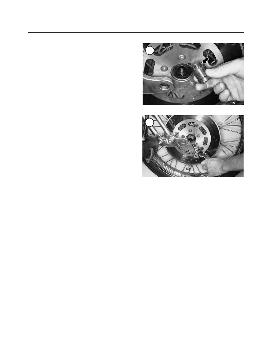
a. Correctly position the bearing spacer (Figure 20)

and install it into the hub.

b. Install the wave washer (Figure 18) onto the bear-

ing spacer.

c. Install the inside washer (large inner diameter)

(Figure 17) onto the bearing spacer.

d. Correctly position the brake caliper mount (Figure

21) and install it onto the bearing spacer.

6. On the right side,

slowly

install the front axle (A, Fig-

ure 15) through the right side fork rocker (C), the outside
washer (small inner diameter), brake caliper mount (B),
front wheel and left side fork rocker.
7. Push the front axle all the way through until it bottoms.
8. On the left side, install the flat washer (Figure 14) and

new

axle nut (Figure 13).

9. Hold the front axle stationery and tighten the axle nut
(Figure 13) to 60-65 ft.-lb. (81-88 N•m).
10. Make sure the front wheel is centered between the
fork rockers. If it is not, check the position of the left and
right bearing spacers.
11. Install the caliper as described in Chapter Thirteen.
12. Install the front fender as described in Chapter Four-
teen.
13. With the front wheel off the ground, rotate it several
times and apply the front brake to seat the brake pads
against the disc.
14. Remove the stand and lower the front wheel to the
ground.

Removal
(Springer Fork [FLSTS Models])

Refer to Figure 22.

1. Support the motorcycle with the front wheel off the
ground. See

Motorcycle Stands

in this chapter.

2. Remove the caliper mounting bolts and remove the
caliper as described in Chapter Thirteen.

NOTE

Place a plastic or wooden spacer between
the brake pads in place of the disc. Then, if
the brake lever is inadvertently applied, the
pistons will not be forced out of the caliper.
If the pistons are forced out, disassemble the
caliper to reseat the pistons.

3. Remove the hub cap and seal from each side. Use the
Harley-Davidson special tool, Hub Cap Remover/In-
staller (part No. HD-41494), or an equivalent.
4. On the left side, remove the retaining pin, then loosen
and remove the front axle nut.
5. Remove the left side outer spacer, nylon insert and
O-ring from the front axle.

NOTE

The front fender will remain attached to the
fork assembly after the front axle is re-
moved.

6. On the right side,

slowly

withdraw the front axle from

the left side fork rocker, rubber spacer, Teflon-coated
washer, brake caliper mount, left side bearing spacer,
front hub, right side bearing spacer and right side fork
rocker. As the front axle is withdrawn, catch the nylon in-
sert and right side outer spacer. The right side O-ring may
come off or stay with the front fender.
7. Pull the wheel away from the fork rockers and remove
it.

NOTE

The wheel bearing spacers are different. La-
bel the bearing spacers before removing them.

386

CHAPTER NINE

20

21

8. Remove the bearing spacers from the right side and the
left side of the wheel.

CAUTION

Do not set the wheel down on the brake disc
surface, as it may be damaged.

9. Inspect the front wheel assembly as described in this
chapter.

Installation
(Springer Fork [FLSTS Models])

1. Clean the axle in solvent and dry it thoroughly. Make
sure the axle bearing surfaces on both fork rockers, the

brake caliper mount bushing, the front fender mounts and
the axle are free of burrs and nicks.
2. Apply an antiseize lubricant to the axle shaft prior to
installation.
3. Install the spacer onto the right side and the left side of
the wheel.
4. Insert the front axle in from the right side as follows:

a. Right side spacer, nylon insert and O-ring.
b. Right side fender brace.
c. Right side rocker.
d. Right side bearing spacer.
e. Through the left side of the hub and the left side

bearing spacer.

f. Brake caliper mount and the Teflon-coated washer.

WHEELS, HUBS AND TIRES

387

9

22

FRONT WHEEL (FLSTS)

1. Hub cap
2. Seal
3. Front axle
4. Spacer (right side)
5. Nylon insert
6. O-ring
7. Retaining ring
8. Spacer (left side)
9. Axle nut

10. Rocker (right side)
11. Bearing spacer (right side)
12. Bearing spacer (left side)
13. Brake caliper mount
14. Teflon washer
15. Rubber spacer
16. Rocker (left side)

g. Rubber spacer and left side rocker.

h. Left side fender brace, O-ring, nylon washer.

5. Push the front axle all the way through until it bottoms.

6. Install a

new

axle nut.

7. Hold the front axle stationery and tighten the axle nut to
60-65 ft.-lb. (81-88 N•m). If necessary, tighten the rear axle
nut to align the nut slot with the axle retaining pin hole.

8. Install the retaining pin and make sure it seats correctly.

9. Make sure the front wheel is centered between the fork
sliders. If it is not, check the position of the left and right
axle spacers.

10. Install the right and left side hub caps and seals. Use
the same tool set-up and tighten the hub cap 1/4 turn after
it make contact with the fender boss.

11. Install the front brake caliper as described in Chapter
Fourteen.

12. With the front wheel off the ground, rotate it several
times and apply the front brake to seat the brake pads
against the disc.

13. Remove the stand and lower the front wheel to the
ground.

Inspection (All Models)

Replace worn or damaged parts as described in this sec-

tion.

1. Turn each bearing inner race by hand (Figure 23, typi-
cal). The bearing should turn smoothly. Some axial play
is normal, but radial play should be negligible. See Figure
24
. If one bearing is damaged, replace both bearings as a
set. Refer to

Front and Rear Hubs

in this chapter.

2. Clean the axle and axle spacers in solvent to remove all
grease and dirt. Make sure the axle contact surfaces are
clean and free of dirt and old grease.

388

CHAPTER NINE

23

24

Radial

Axial

25

3. On Springer fork models, inspect the Teflon-coated
washers. If the coating is worn through to expose the brass
underneath; replace the washer.
4. Check the axle runout with a set of V-blocks and a dial
indicator (Figure 25).
5. Check the spacers for wear, burrs and damage. Replace
as necessary.
6. Check the brake disc bolts for tightness. To service the
brake disc, refer to Chapter Twelve.
7. Check wheel runout and spoke tension (laced wheels)
as described in this chapter.

REAR WHEEL

Removal

1. On models so equipped, remove saddlebags as de-
scribed in Chapter Fourteen.
2. Remove both mufflers as described in Chapter Seven.
3. Support the motorcycle with an appropriate size jack
with the rear wheel off the ground.
4. On models equipped with the optional chrome cover,
perform the following:

a. Remove the bolts and the rear axle chrome cover

(Figure 26).

b. If necessary, remove the mounting bracket (Figure

27) from the drive belt adjuster.

5. Remove the bolts securing the drive belt guard (Figure
28
) and the debris deflector (Figure 29). Remove the belt
guard and the deflector.

NOTE

The rear wheel is heavy and can be difficult
to remove. Check the tire-to-ground clear-
ance before removing the rear axle. If neces-
sary, have an assistant help in the removal
or place wooden blocks under it.

6. On HDI models, remove the axle nut cover.
7. Remove the spring clip (Figure 30) and loosen the rear
axle nut.

NOTE

Prior to removing the axle nut, mark the
wheel bearing spacers and adjuster collars
with a R (right side) and L (left side). The
spacers and collars are unique and must be
reinstalled onto the correct side of the wheel
during installation.

8. Loosen and remove the axle nut and washer (Figure 31).
9. Remove the rear brake pads as described in Chapter
Thirteen.

WHEELS, HUBS AND TIRES

389

9

26

27

28

29

10. Loosen the jam nut (A, Figure 32) and completely
loosen the drive belt adjuster (B) on each side of the swing
arm to allow maximum slack in the drive belt.
11. On the left side, remove the adjuster collar (Figure
33
) from the rear axle.
12. On the left side, use a soft-faced mallet and gently tap
the rear axle toward the right side. Remove the left side
spacer.
13. From the right side, withdraw the rear axle (Figure
34
) while holding onto the rear wheel. Remove the right
side spacer. Lower the wheel to the wooden blocks or the
ground.
14. Move the rear wheel forward and lift the drive belt off
the driven sprocket.
15. Lift the rear caliper and move it toward the front of
the motorcycle until the caliper notch clears the tab on the
swing arm. Move the caliper out of the way and secure it
with a bungee cord.
16. Raise the motorcycle sufficiently to allow the rear
wheel to roll toward back and clear the rear fender.
17. Remove the rear wheel (Figure 35) and lower the
motorcycle to a safe level.
18. If still in place, remove the wheel spacers from the
right side and the left side of the wheel.

NOTE

Place a plastic or wooden spacer between
the brake pads in place of the disc. Then, if
the brake pedal is inadvertently depressed,
the pistons will not be forced out of the cali-
per. If the pistons are forced out, disassem-
ble the caliper to reseat the pistons.

CAUTION

Do not set the wheel down on the brake disc
surface, as it may be damaged.

19. Install the wheel bearing spacers, adjuster collars and
nut onto the axle in the same order of removal (Figure
36
).

390

CHAPTER NINE

31

32

33

34

30

20. Inspect the rear wheel as described in this chapter.

Installation

CAUTION

The rear wheel bearing spacer must be in-
stalled onto the correct side of the rear
wheel. If installed incorrectly, the wheel will
be off-set to the wrong side within the swing
arm. This will result in the drive belt being
out of alignment with the driven sprocket re-
sulting in rapid drive belt wear.

1. Remove the wheel bearing spacers, adjuster collars
and nut from the rear axle and keep them in the same order
(Figure 36).
2. Clean the axle in solvent and dry it thoroughly. Make
sure the bearing surfaces on the axle are free of burrs and
nicks.
3. Apply an antiseize lubricant to the axle shaft prior to
installation.
4. Raise the motorcycle sufficiently to allow the rear
wheel to roll forward and clear the rear fender.
5. Move the rear caliper into position and onto the locat-
ing tab on the swing arm (Figure 37).
6. Move the rear wheel forward (A, Figure 38) and in-
stall the drive belt onto the driven sprocket.
7. Lower the motorcycle to a level where the rear axle can
be installed.
8. Make sure the right side axle adjuster (A, Figure 39) is
in place on the rear axle.
9. Move the rear wheel into position and align it with the
swing arm.
10. Move the rear caliper (B, Figure 38) up into position
and align it with the rear axle receptacles in the swing arm.
11. Install the right side bearing spacer onto the wheel
and hold it in place.
12. From the right side, carefully install the rear axle
(Figure 34) through the right side of the swing arm, the

WHEELS, HUBS AND TIRES

391

9

35

36

37

38

39

rear caliper (B, Figure 38), the right side bearing spacer
(C) and rear hub.
13. Install the left side bearing spacer onto the wheel and
hold it in place.
14. Continue to push the rear axle through the left side
bearing spacer (A, Figure 40) and the swing arm.
15. Install the left side axle adjuster (B, Figure 40),
washer and axle nut (C). Tighten the axle nut finger-tight
at this time.
16. After the rear axle is installed, make sure both bearing
spacers and axle adjusters are in the correct location and
are still in place. The notch in the axle adjuster must align
with the tip of the drive belt adjuster (Figure 41). Reposi-
tion at this time if incorrect.
17. Install the rear brake pads as described in Chapter
Thirteen.
18. Check drive belt tension and adjustment as described
in Chapter Three.
19. Tighten the rear axle nut to 60-65 ft.-lb. (81-88 N•m).
If necessary, tighten the rear axle nut to align the nut slot
with the axle spring pin hole. Install the spring pin (Fig-
ure 42
) and snap it into place (Figure 30).
20. On HDI models, install the axle nut cover.
21. Install the drive belt debris deflector (Figure 29) and
guard (Figure 28) and tighten the bolts securely.
22. On models equipped with the optional chrome cover,
perform the following:

a. If removed, install the mounting bracket (Figure

27) onto the drive belt adjuster.

b. Install the rear axle chrome cover (Figure 26) and

bolts and tighten securely.

23. Install both mufflers as described in Chapter Seven.
24. Rotate the wheel several times to make sure it rotates
freely. Then apply the rear brake pedal several times to
seat the pads against the disc.
25. Remove the stand and lower the rear wheel to the
ground.
26. On models so equipped, install the saddlebags as de-
scribed in Chapter Fourteen.

Inspection

Replace worn or damaged parts as described in this sec-

tion.
1. Turn each bearing inner race by hand (Figure 43). The
bearing should turn smoothly. Some axial play is normal,
but radial play should be negligible. See Figure 24. If one
bearing is damaged, replace both bearings as a set. Refer
to

Front and Rear Hubs

in this chapter.

2. Clean the axle and axle spacers in solvent to remove all
grease and dirt. Make sure the axle contact surfaces are
free of dirt and old grease.

3. Check the axle runout with a set of V-blocks and a dial
indicator (Figure 25).

4. Check the bearing spacers and axle adjusters (Figure
36
) for wear, burrs and damage. Replace as necessary.

5. Check the brake disc bolts (Figure 44) for tightness.
To service the brake disc, refer to Chapter Twelve.

6. Check the final drive sprocket bolts (Figure 45) for
tightness. Service for the final drive sprocket is covered in
this chapter.

392

CHAPTER NINE

40

41

42

7. Check wheel runout and spoke tension as described in
this chapter.

FRONT AND REAR HUBS

Sealed ball bearings are installed on each side of the

hub. Do not remove the bearing assemblies unless they re-
quire replacement.

Preliminary Inspection

Inspect each wheel bearing prior to removing it from

the wheel hub.

CAUTION

Do not remove the wheel bearings for in-
spection as they will be damaged during the
removal process. Remove wheel bearings
only if they are to be replaced.

1. Perform Steps 1-3 of

Disassembly

in the following

procedure.
2. Turn each bearing by hand (Figure 46). The bearings
should turn smoothly with no roughness.
3. Inspect the play of the inner race of each wheel bear-
ing. Check for excessive axial play and radial play (Fig-
ure 24
). Replace the bearing if free play is excessive.

Disassembly

This procedure applies to both the front and rear wheel

and hub assemblies. Differences between the different
hubs are identified. Refer to Figures 47 and 48.
1A. Remove the front wheel as described in this chapter.
1B. Remove the rear wheel as described in this chapter.
2. Remove the axle spacers from each side of the hub if
they are still in place.
3. If necessary, remove the bolts securing the brake disc
(Figure 44) and remove the disc.
4. Before proceeding, inspect the wheel bearings as de-
scribed in this chapter. If they must be replaced, proceed
as follows.
5A. If the special tools are not used, perform the following:

a. To remove the right and left bearings and spacer

collar, insert a soft aluminum or brass drift into one
side of the hub.

b. Push the spacer collar over to one side and place the

drift on the inner race of the lower bearing.

c. Tap the bearing out of the hub with a hammer, work-

ing around the perimeter of the inner race (Figure
49
). Remove the bearing and distance collar.

WHEELS, HUBS AND TIRES

393

9

44

45

46

43

394

CHAPTER NINE

47

FRONT WHEELS

1. Front axle

(all models except FXSTD)

2. Hub cap spacer (FLSTC)
3. Hub cap (FLSTC)
4. Snap ring (FLSTC)
5. Acorn nut (FXSTD)
6. Front axle ( FXSTD)
7. Spacer—right side

(all models except FXSTD 2002-on)

8. Spacer—right side (FXSTD 2002-on)

9. Wheel bearing

10. Spacer sleeve
11. Hub (laced wheel)
12. Laced wheel
13. Cast wheel
14. Screw
15. Cover
16. Spacer (left side)
17. Brake disc
18. Bolt

19. Acorn nut (FXSTD)
20. Retaining pin (FLSTS)
21. Washer
22. Lockwasher
23. Nut (all models except FXSTD)
24. Valve stem cap
25. Balance weight (cast wheel)
26. Balance weight (laced wheel)
27. Valve stem
28. Valve stem nut (laced wheel)

WHEELS, HUBS AND TIRES

395

9

48

REAR WHEEL

1. Laced wheel
2. Hub (laced wheel)
3. Brake disc
4. Wheel bearing
5. Rear axle
6. Spacer (right side)
7. Disc wheel
8. Cast wheel

9. Seal ring

10. Driven sprocket
11. Washer
12. Bolt
13. Spacer sleeve
14. Wheel bearing
15. Spring clip
16. Spacer (left side)

17. Washer
18. Axle nut
19. Axle nut cover (HDI models)
20. Valve stem cap
21. Balance weight (cast wheel)
22. Balance weight (laced wheel)
23. Valve stem
24. Valve stem nut (laced wheel)

d. Repeat sub steps b and c for the bearing on the other

side.

NOTE

The Kowa Seiki Wheel Bearing Remover set
can be ordered through a K&L Supply Co.
dealer.

WARNING

Be sure to wear safety glasses while using
the wheel bearing remover set.

5B. To remove the bearings with the Kowa Seiki Wheel
Bearing Remover set, perform the following:

a. Select the correct size remover head tool and insert

it into the bearing.

b. Turn the wheel over and insert the remover shaft

into the backside of the adapter. Tap the wedge and
force it into the slit in the adapter (Figure 50). This
will force the adapter against the bearing inner race.

c. Tap the end of the wedge bar with a hammer (Fig-

ure 51) to drive the bearing out of the hub. Remove
the bearing and the distance collar.

d. Repeat substeps a-c for the bearing on the other

side.

6. Clean the inside and the outside of the hub with sol-
vent. Dry it with compressed air.

Assembly

CAUTION

The removal process will generally damage
the bearings. Replace the wheel bearings in
pairs.

Never

reinstall bearings after they

are removed. Always install

new

bearings.

1. Blow any debris out of the hub prior to installing the
new bearings.
2. Apply a light coat of wheel bearing grease to the bear-
ing seating areas of the hub. This will make bearing instal-
lation easier.

CAUTION

Install non-sealed bearings with the single
sealed side facing outward. Tap the bear-
ings squarely into place and tap on the outer
race only. Do not tap on the inner race or
the bearing might be damaged. Make sure
the bearings are completely seated.

3. Select a driver, or socket (Figure 52), with an outside di-
ameter slightly smaller than the bearing’s outside diameter.
4. Tap the right side bearing squarely into place and tap on
the outer race only. Tap the bearing into the hub bore until it
bottoms. Make sure the bearing is completely seated.

5. Turn the wheel over (right side up) on the workbench
and install the spacer collar.
6. Use the same tool set-up to drive in the left side bearing.
7. If the brake disc was removed, install it as described in
Chapter Thirteen.
8A. Install the front wheel as described in this chapter.
8B. Install the rear wheel as described in this chapter.

DRIVEN SPROCKET ASSEMBLY

Inspection

Inspect the sprocket teeth (Figure 53). If the teeth are

visibly worn, replace the drive belt and both sprockets.

Removal/Installation

1. Remove the rear wheel as described in this chapter.
2. Remove the bolts and washers (Figure 45) securing
the driven sprocket to the hub, and remove the sprocket.
3. Position the driven sprocket onto the rear hub.
4. Apply a light coat of ThreeBond TB1360, or an equiv-
alent, to the bolts prior to installation.
5. Install the bolts and washers and tighten the bolts to
55-60 ft.-lb. (75-81 N•m).

DRIVE SPROCKET

The drive sprocket is covered in Chapter Six under

Transmission Drive Sprocket

.

396

CHAPTER NINE

49

Distance collar

DRIVE BELT

CAUTION

When handling a new or used drive belt,
never wrap the belt in a loop smaller than 5
in. (130 mm) or bend it sharply. This will
weaken or break the belt fibers and cause
premature belt failure.

Removal

NOTE

If the existing drive belt is being reinstalled,
install it so it travels in the same direction.
Before removing the belt, draw an arrow on
the top surface of the belt facing forward.

1. Remove the exhaust system as described in Chapter
Seven.
2. Remove the compensating sprocket and clutch as de-
scribed in Chapter Five.
3. Remove the primary chain inner housing as described
in Chapter Five.
4. Remove the rear wheel as described in this chapter.
5. Remove the two bolts (A, Figure 54) securing the in-
ner fender panel. Move the inner fender up to release if
from the frame hook and remove the inner fender panel
(B).
6. Place wooden blocks or a floor jack under the trans-
mission and engine assembly to support it after the swing
arm pivot shaft is partially removed.
7. On the right side, secure the pivot shaft (Figure 55) to
keep it from rotating in the following step.
8. On the left side, loosen and remove the pivot shaft
flange nut and hardened washer (Figure 56).
9. Support the swing arm on a box and tap on the left side
of the pivot shaft with a drift.
10. Drive the pivot shaft from the left side of the frame
until the left side spacer collar (Figure 57) can be re-
moved, then remove it from between the swing arm and

WHEELS, HUBS AND TIRES

397

9

53

52

51

50

Bearing

Hub

Bearing

Remover shaft

Remover head

the transmission case. Do not drive the pivot shaft out any
farther than necessary.
11. Remove the drive belt (Figure 58) from the drive
sprocket and remove the drive belt from between the
swing arm and transmission case.
12. If the drive belt is going to remain off for a period of
time, install the left side spacer collar and tap the pivot
shaft back into place through the collar and the frame. In-
stall the nut and tighten securely.

Installation

NOTE

If the existing drive belt is being reinstalled,
install it so it travels in the same direction as
noted prior to removal. If a new drive belt is
being installed, it can be installed in either
direction.

1. Insert the drive belt through the space between the
swing arm and the transmission case.
2. Install the drive belt onto the drive sprocket.
3. If reinstalled, remove the nut from the pivot shaft and
drive the pivot shaft out until it is flush with the left side of
the transmission case.
4. Position the left side spacer collar (Figure 57) with the
flange side facing the transmission case and install it be-
tween the transmission case and the swing arm.
5. Push the pivot shaft through the left side spacer collar,
the swing arm bushing and left side of the frame pivot
area. Push the pivot shaft in until it bottoms.

NOTE

Do not substitute another type of washers in
place of the hardened washers.

6. Install the

L

marked hardened washer onto the pivot

shaft.
7. On the right side, secure the pivot shaft (Figure 55) to
keep it from rotating in the following step.
8. Apply ThreeBond No. 1360 (red) threadlocking com-
pound to the pivot shaft threads prior to installing the
flange nut.
9. On the left side, install the flange nut (Figure 56) and
tighten to 90-110 ft.-lb. (122-149 N•m).
10. Slowly raise and lower the swing arm to ensure ease
of movement. If binding occurs, repeat Step 9 and correct
the problem.
11. Install the inner fender and hook it onto the frame
hook. Install the two bolts (A, Figure 54) securing the in-
ner fender (B) and tighten securely.
12. Install the rear wheel as described in this chapter.

13. Remove the wooden blocks or floor jack from under
the transmission and engine assembly.

14. Install the primary chain inner housing as described
in Chapter Five.

15. Install the compensating sprocket and clutch as de-
scribed in Chapter Five.

16. Install the exhaust system as described in Chapter
Seven.

Inspection

Do not apply any type of lubricant to the drive belt. In-

spect the drive belt and teeth (Figure 59) for severe wear,
damage or oil contamination.

398

CHAPTER NINE

54

55

56

11. Install one of the caliper mounting bolts through the
upper hole (A, Figure 78) to correctly align the caliper
halves.
12. Install the two caliper body bolts (B, Figure 78) and
tighten them securely. They will be tightened to the speci-
fication after the caliper is installed on the front fork.
13. If the bleed valve assembly was removed, install it
and tighten it to 80-100 in.-lb. (9-11 N•m).
14. Install the caliper and brake pads as described in this
chapter.
15. Tighten the two caliper body mounting bolts (A, Fig-
ure 64
) to 28-38 ft.-lb. (38-52 N•m).
16. Bleed the brakes as described under

Bleeding the Sys-

tem

in this chapter.

FRONT MASTER CYLINDER

Removal

CAUTION

Cover the fuel tank and front fender with a
heavy cloth or plastic tarp to protect them
from accidental brake fluid spills. Wash
brake fluid off painted, plated, or plastic
surfaces immediately as it will destroy most
surfaces it contacts. Use soapy water and
rinse completely.

1. On models so equipped, remove the windshield as de-
scribed in Chapter Fourteen.
2. Remove the mirror (A, Figure 79) from the master cylinder.
3. Clean the top of the master cylinder of all dirt and debris.

CAUTION

Failure to install the spacer in Step 2 will re-
sult in damage to the rubber boot and plunger
on the front brake switch.

4. Insert a 5/32 in. (4 mm) thick spacer between the brake
lever and lever bracket. Make sure the spacer stays in place
during the following steps.
5. On models so equipped, remove the master cylinder
chrome cover (B, Figure 79).
6. Remove the screws securing the cover (A, Figure 80),
and remove the cover (B) and diaphragm.
7. Use a shop syringe to draw all of the brake fluid out of the
master cylinder reservoir. Temporarily reinstall the dia-
phragm and the cover. Tighten the screws finger-tight.
8. Remove the banjo bolt and sealing washers (C, Figure
79
) securing the brake hose to the master cylinder.
9. Place the loose end of the brake hose in a reclosable
plastic bag to prevent the entry of moisture and debris. Tie
the loose end of the hose to the handlebar.

10. Remove the screw securing the right side switch to-
gether and separate the switch.

11. Remove the bolts and washers securing the clamp and
master cylinder to the handlebar.

12. Remove the master cylinder assembly from the han-
dlebar.

13. Drain any residual brake fluid from the master cylin-
der and dispose of it properly.

14. If the master cylinder assembly is not going to be ser-
viced, reinstall the clamp and Torx bolts to the master cyl-

498

CHAPTER THIRTEEN

78

79

80

inder. Place the assembly in a reclosable plastic bag to
protect it from debris.

Installation

1. Insert the 5/32 in. (4 mm) thick spacer between the brake
lever and lever bracket if not in place. Make sure the spacer
stays in place during the following steps.

2. Position the front master cylinder onto the handlebar.
Align the master cylinder notch (Figure 81) with the lo-
cating tab on the lower portion of the right side switch.

CAUTION

Do not damage the front brake light switch
and rubber boot (

Figure 82

, typical) when

installing the master cylinder in Step 3.

3. Push the master cylinder all the way onto the handlebar
(A, Figure 83). Hold it in this position and install the up-
per portion of the right side switch (B, Figure 83). Install
the switch’s clamping screw and tighten it securely.
4. Position the clamp and install the bolts and washers.
Tighten the upper mounting bolt, then the lower bolt.
Tighten the bolts to 70-80 in.-lb (8-9 N•m).
5. Apply clean DOT 5 brake fluid to the rubber portions of
the new sealing washers prior to installation.
6. Install

new

sealing washers and the banjo bolt (C, Fig-

ure 79) securing the brake hose to the master cylinder.
Tighten the banjo bolt to 17-22 ft.-lb. (23-30 N•m).
7. Remove the spacer from the brake lever.
8. Install the mirror (A, Figure 79) onto the master cylinder.
9. On models so equipped, install the windshield or front
fairing.
10. Temporarily install the diaphragm and top cover (B,
Figure 80) onto the reservoir. Tighten the screws fin-
ger-tight at this time.
11. On models so equipped, install the master cylinder
chrome cover (B, Figure 79).
12. Refill the master cylinder reservoir and bleed the
brake system as described under

Bleeding the System

in

this chapter.
13. On models so equipped, install the windshield as de-
scribed in Chapter Fourteen.

Disassembly

1. Store the master cylinder components (Figure 84) in a
divided container, such as a restaurant-size egg carton, to
help maintain their correct alignment positions.
2. Remove the screws securing the top cover if they are
still in place. Remove the top cover and the diaphragm
from the master cylinder.
3. Remove the master cylinder assembly as described in
this chapter.
4. Remove the snap ring (A, Figure 85) and pivot pin se-
curing the hand lever to the master cylinder. Remove the
hand lever (B, Figure 85).
5. Remove the retainer (A, Figure 86) and the rubber
boot (B) from the area where the hand lever actuates the
piston assembly.
6. Remove the piston assembly (Figure 87) and the
spring.
7. Inspect all parts as described in this section.

BRAKES

499

13

82

83

81

Inspection

Replace worn or damage parts as described in this sec-

tion. It is recommended that a new piston kit assembly be
installed every time the master cylinder is disassembled.

1. Clean all parts in isopropyl alcohol or clean DOT 5
brake fluid. Inspect the body cylinder bore surface for
signs of wear and damage. If it is less than perfect, replace
the master cylinder assembly. The body cannot be re-
placed separately.

2. Inspect the piston cup (A, Figure 88) and O-ring (B)
for signs of wear and damage.

3. Make sure the fluid passage (Figure 89) in the bottom of
the master cylinder reservoir is clear. Clean it out if necessary.

4. Inspect the piston contact surface for signs of wear and
damage.

5. Check the end of the piston (C, Figure 88) for wear
caused by the hand lever.

6. Check the hand lever pivot lugs in the master cylinder
body for cracks or elongation.

7. Inspect the hand lever pivot hole and bushing (A, Figure
90
), and the pivot pin (B) for wear, cracks or elongation.

8. Inspect the piston cap and retainer (Figure 91) for wear
or damage.

500

CHAPTER THIRTEEN

84

85

86

FRONT MASTER CLYINDER

1. Screw
2. Sight glass
3. Top cover
4. Diaphram
5. Pivot pin
6. T27 Torx screw
7. Washer
8. Clamp
9. Body

10. Piston assembly
11. Bushing
12. Hand lever
13. Snap ring
14. Washer
15. Acorn nut


Content      ..     34      35      36      37     ..