Harley Davidson Softail 2000-2005. Service manual - page 18
 

  Главная      Harley Davidson     Harley Davidson Softail 2000-2005. Service manual


Search            copyright infringement  


Content      ..     16      17      18      19     ..


Harley Davidson Softail 2000-2005. Service manual - page 18


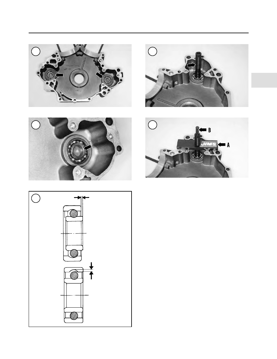
5. Insert the bearing puller onto the bearing and tap it into
place (Figure 401) with a plastic mallet. Make sure the
puller is seated correctly under the bearing inner race.
6. Install the plate (A, Figure 402) onto the puller and
rest it flush with the crankcase sealing surface.
7. Insert the rod (B, Figure 402) into the puller and push
it in until it bottoms.
8. Install the brass washer (A, Figure 403) and large nut
(B) onto the puller and plate.
9. Secure the puller with a 5/8 in. open end wrench to
keep it from rotating.

CAUTION

Do not turn the puller with the 5/8 in.
wrench, just keep it from rotating.

10. Using a 1 1/8 in. wrench on the large nut (B, Figure
403
), tighten the large nut until the bearing is pulled free
from the crankcase receptacle.
11. Place the left side crankcase half on towels or shop
cloths to protect the exterior finish. Place the crankcase on
wooden blocks on the press bed.
12. Apply a light coat of clean engine oil to the crankcase
bearing receptacle and to the bearing outer race surface.
13. Place the bearing onto the bearing receptacle.
14. Place the installer collar (Figure 404) onto the bearing.

ENGINE

197

4

400

401

399

398

Axial

Radial

402

15. Center the press ram directly over the installer collar and
slowly press the bearing into the crankcase until it is seated.
16. Remove the crankcase and special tools from the press.
17. Rotate the bearing to make sure it rotates freely.
18. Repeat Steps 3-17 for the other bearing if necessary.

Outer support bearing replacement

A crankcase bearing remover (part No. HD-44065) and hy-

draulic press are required to replace the outer support bearing.
1. Remove the balancer shaft support as described in this
chapter.
2. Thoroughly clean the support in solvent and dry with
compressed air.
3. Place the bearing remover (A, Figure 405) on the press bed.
4. Place the bearing shaft support (B, Figure 405) upside
down on the bearing remover.
5. Place a pilot (C, Figure 405) or suitable size socket
onto the bearing outer race.
6. Center the press ram (D, Figure 405) over the pilot or
socket.
7. Slowly apply pressure and remove the bearing and re-
taining ring from the support.
8. Release press pressure and remove the pilot or socket.
9. Discard the bearing and retaining ring.
10. Thoroughly clean the bore of the support and dry with
compressed air.
11. Apply clean engine oil to the support bore surface and
to the outer surface of the bearing.
12. Place the balancer shaft support (A, Figure 406) on a
piece of wood on the press bed.
13. Install a

new

retaining ring onto the

new

bearing and

make sure it seats correctly in the bearing groove.
14. Position the

new

bearing (B, Figure 406) and retain-

ing ring (C) with the bearing letters facing up.
15. Place the bearing onto the support.
16. Place a pilot (D, Figure 406) or suitable size socket
onto the bearing outer race.

198

CHAPTER FOUR

403

404

405

406

17. Center the press ram (E, Figure 406) over the pilot or
socket.
18. Slowly apply pressure and press the bearing and re-
taining ring into the support until the retaining (C, Figure
406
) fits flush against the housing surface.
19. Release press pressure and remove the pilot or socket.
20. Rotate the new bearing and make sure it rotates freely.

ENGINE BREAK-IN

Following cylinder service such as boring, honing and

installing new rings, or major lower end work, break-in

the engine as though it were new. The service and perfor-
mance life of the engine depends on the break-in.

1. For the first 50 mi. (80 km), maintain engine speed be-
low 2500 rpm in any gear. However, do not lug the engine.
Do not exceed 50 mph during this period.

2. From 50-500 mi. (80-804 km), vary the engine speed.
Avoid prolonged steady running at one engine speed. Dur-
ing this period, increase engine speed to 3000 rpm. Do not
exceed 55 mph.

3. After the first 500 mi. (804 km), the engine break-in is
complete.

Table 1  GENERAL ENGINE SPECIFICATIONS

Item

Specifications

Engine type

Four- stroke, 45 ° OHV V twin,

Twin Cam 88B (balanced)

Bore and stroke

3.75 × 4.00 in. (95.25 × 101.6 mm)

Displacement

88 cubic inch (1450 cc)

Compression ratio

9.0 to 1

Torque

82 ft. lb. (111 N•m) @ 3000 rpm

Maximum sustained engine speed

5600 rpm

Engine and transmission weight

204 lbs. (92.5 kg)

Cooling system

Air-cooled

Table 2  ENGINE SERVICE SPECIFICATIONS

New

Service limit

Item

in. (mm)

in. (mm)

Cylinder head

Warp

0.006 (0.15)

Valve guide fit in head

0.0020-0.0033 (0.051-0.084)

0.002 (0.051)

Valve seat fit in head

0.003-0.0045 (0.076-0.114)

0.002 (0.051)

Rocker arm

Shaft-to-rocker arm bushing

0.0005-0.0020 (0.013-0.051)

0.0035 (0.089)

Shaft-to-rocker arm support

0.0007-0.0022 (0.018-0.056)

0.0035 (0.089)

End clearance

0.003-0.0013 (0.076-0.033)

0.025 (0.635)

Valves

Valve stem-to-guide clearance

Intake

0.0008-0.0026 (0.020-0.066)

Exhaust

0.0015-0.0033 (0.038-0.084)

Seat width

0.040-0.062 (1.02-1.58)

ENGINE

199

4

(continued)

b. Inspect the release plate, left side pushrod and

locknut for wear or damage.

c. Inspect the snap ring groove for damage (Figure

21).

d. Position the release plate with the OUT mark facing

out (Figure 22) and install the assembly into the
pressure plate.

e. Install the snap ring and make sure it is correctly

seated in the pressure plate groove.

Installation

NOTE

The original equipment clutch (

Figure 10

)

has nine friction plates, eight steel plates,
one damper spring and one damper spring
seat. Make sure each part is installed. When
installing an aftermarket clutch plate as-
sembly, follow the manufacturer’s instruc-
tions.

1. Soak the clutch friction disc and clutch plates in new
primary drive oil for approximately five minutes before
installing them.

CLUTCH AND PRIMARY DRIVE

209

5

17

18

19

20

21

22

2. Install the damper spring seat (Figure 23) into the
clutch hub and push it in until it seats within the clutch
hub.
3. Position the damper spring with the dished side facing
out and install it onto the clutch hub against the damper
spring seat (Figure 24).

NOTE

There are two different types of clutch fric-
tion discs (

Figure 25

). The wider friction

disc A is the normal width disc. The narrow
width friction disc B is installed first, as it
works in conjunction with the damper
spring and damper spring seat.

4. Install the clutch friction disc

B

(Figure 26) onto the

clutch shell and clutch hub. Push it on until it bottoms
within the clutch hub and the damper spring and damper
spring seat.
5. Install a clutch plate (Figure 27), then a friction disc

A

(Figure 28). Continue to alternately install the clutch
plates and friction discs. The last part installed is a friction
disc

A

(Figure 29). Make sure it is locked into place in the

clutch shell (Figure 30).
6. Install the pressure plate onto the clutch hub (Figure
31
).

210

CHAPTER FIVE

23

24

25

26

27

28

7. Position the diaphragm spring with the dished side fac-
ing out and install it onto the pressure plate (Figure 32).
Hold the pressure plate in place.

8. Position the diaphragm spring retainer with the finger
side (Figure 33) facing in toward the diaphragm spring
and install the diaphragm spring retainer (Figure 34) and
bolts.

9. Tighten the bolts (Figure 35) in a crisscross pattern to
90-110 in.-lb. (10-12 N•m).

10. Make sure the left side pushrod and nut (A, Figure
36
) are in place, then install the release plate (B).

11. Secure the release plate with the snap ring (Figure
37
). Make sure the snap ring is seated correctly in the
pressure plate groove (Figure 38).

12. Install the primary chaincase cover as described in
this chapter.

13. Install the clutch mechanism inspection cover and
quad ring.

14. Connect the negative battery cable as described in
Chapter Eight.

CLUTCH AND PRIMARY DRIVE

211

5

29

30

31

32

33

34

CLUTCH SHELL, COMPENSATING SPROCKET

AND PRIMARY DRIVE CHAIN

Removal

This procedure describes clutch shell (Figure 39), pri-

mary chain and compensating sprocket removal (Figure
40
). These components must be removed from the engine
and transmission as an assembly.

NOTE

On models so equipped, always disarm the
optional TSSM security system prior to dis-
connecting the battery or the siren will
sound.

1. Disconnect the negative battery cable as described in
Chapter Eight.

2. Remove the primary chaincase cover as described in
this chapter.

3. If necessary, remove the diaphragm spring, pressure
plate, clutch plates and friction discs as described in this
chapter. This procedure is shown with these components
removed.

4A. If a special tool is available, such as a primary drive
locking tool (JIMS part No. 2234), place it onto the pri-
mary chain next to the clutch housing (Figure 41).

4B. If the special tool is not available, shift the transmis-
sion into fifth gear. Have an assistant apply the rear brake.

CAUTION

The clutch nut has

left-hand threads

. Turn

the clutch nut

clockwise

to loosen it.

5. Loosen the clutch nut with an impact wrench. Remove
the clutch nut (Figure 42).

6. Loosen the compensating sprocket nut with an impact
wrench.

7. Remove the compensating sprocket nut, cover assembly
(Figure 44) and sliding cam (A, Figure 45).

8. Loosen the primary chain shoe adjuster locknut (B, Fig-
ure 45
) and push the tensioner assembly down (C) to relieve
tension on the primary chain. Remove the locknut.

9. Remove the compensating sprocket (A, Figure 46), pri-
mary chain (B) and clutch assembly (C) at the same time.

10. Remove the shaft extension (Figure 47) and the
spacer (Figure 48).

11. Inspect the various components as described in this
chapter.

212

CHAPTER FIVE

36

37

38

35

Installation

1. Remove all threadlocking compound residue from the
crankshaft and mainshaft threads, and from the compen-
sating sprocket nut and the clutch nut.

2. Remove all gasket residue from the inner primary
housing gasket surfaces.

3. Install the spacer (Figure 48) and the shaft extension
(Figure 47) onto the crankshaft.

4. Assemble the compensating sprocket, primary chain
and clutch.

5. Install the compensating sprocket (A, Figure 46), pri-
mary chain (B) and clutch assembly (C) at the same time.

6. Install the sliding cam (A, Figure 45) and the cover as-
sembly (Figure 44).

7A. Install the same tool set-up (Figure 41) used during
removal to prevent the compensating sprocket and clutch
shell from rotating during the following steps.

CLUTCH AND PRIMARY DRIVE

213

5

39

CLUTCH ASSEMBLY

1. Snap ring
2. Clutch shell and sprocket
3. Bearing
4. Snap ring
5. Clutch hub
6. Clutch nut
7. Diaphragm spring seat
8. Diaphragm spring
9. Friction disc B

10. Clutch plates
11. Friction disc A
12. Pressure plate
13. Diaphragm spring
14. Diaphragm spring

retainer

15. Bolt
16. Release plate
17. Snap ring

18. Snap ring
19. Thrust washer
20. Radial bearing
21. Oil slinger
22. Pushrod (right side)
23. Pushrod (right side)
24. Pushrod (left side)
25. Locknut

CAUTION

When using the clutch holder in Step 7B,
make sure to secure it squarely onto the
clutch shell. If the clutch holder starts to
slip, stop tightening the clutch nut and repo-
sition the clutch holder. If the clutch holder
slips while tightening the clutch nut, it may
damage the clutch shell splines.

7B. If the special tool is not available, hold the clutch shell
with a clutch holder (A, Figure 49).

214

CHAPTER FIVE

40

COMPENSATING SPROCKET

1. Bolt
2. Anchor plate
3. Screw
4. Washer
5. Nut
6. Primary chain
7. Chain tensioner
8. Tensioner pad
9. Snap ring

10. Spacer
11. Shaft extensioner
12. Compensating sprocket
13. Sliding cam
14. Cover assembly

with spring

15. Nut

41

42

43

NOTE

The clutch nut has

left-hand threads

. Turn

the nut

counterclockwise

to tighten it.

8. Apply two drops of ThreeBond TB1360 or an equiva-
lent to the clutch nut threads. Install the nut (Figure 42) and
tighten it (B, Figure 49) to 70-80 ft.-lb. (95-108 N•m).

9. Apply two drops of ThreeBond TB1360 or an equiva-
lent to the compensating sprocket nut threads. Install the
nut (Figure 43) and tighten it (Figure 50) to 150-165
ft.-lb. (203-204 N•m).

10. If used, remove the special tool from the clutch shell.

11. Adjust the primary chain as described in Chapter Three.

12. If removed, install the clutch plates and friction discs,
pressure plate, and the diaphragm spring as described in
this chapter.

13. Install the primary chaincase outer cover as described
in this chapter.

14. Adjust the clutch as described in Chapter Three.

15. Connect the negative battery cable as described in
Chapter Eight.

CLUTCH AND PRIMARY DRIVE

215

5

45

44

46

47

48

49

CLUTCH SHELL, CLUTCH HUB

AND SPROCKET

Inspection

The clutch shell is a subassembly consisting of the clutch

shell, the clutch hub, the bearing and two snap rings.
1. Remove the clutch shell as described in this chapter.
2. Hold the clutch shell and rotate the clutch hub by hand.
The bearing is damaged if the clutch hub binds or turns
roughly.
3. Check the sprocket (A, Figure 51) and the starter ring
gear (B) on the clutch shell for cracks, deep scoring, ex-
cessive wear or heat discoloration.
4. If the sprocket or ring gear is worn or damaged, replace
the clutch shell. If the primary chain sprocket is worn, also
check the primary chain and the compensating sprocket as
described in this chapter.
5. Inspect the clutch hub for the following conditions:

a. The clutch plate teeth slide in the clutch hub splines

(A, Figure 52). Inspect the splines for rough spots,
grooves or other damage. Repair minor damage
with a file or oil stone. If the damage is severe, re-
place the clutch hub.

b. Inspect the clutch hub inner splines (Figure 53) for

galling, severe wear or other damage. Repair minor
damage with a fine cut file. If damage is severe, re-
place the clutch hub.

c. Inspect the bolt towers and threads (B, Figure 52)

for thread damage or cracks at the base of the tower.
Repair thread damage with the correct size metric
tap. If any of the towers are cracked or damaged, re-
place the clutch hub.

6. Check the clutch shell. The friction disc tangs slide in
the clutch housing grooves (C, Figure 52). Inspect the
grooves for cracks or galling. Repair minor damage with a
file. If the damage is severe, replace the clutch housing.
7. If the clutch hub, clutch shell or bearing is damaged,
replace them as described in the following procedure.

Disassembly/Assembly

Do not separate the clutch hub and shell unless either

part or the bearing is going to be replaced. If the two parts
are separated, the bearing will be damaged. Removal and
installation of the bearing requires a hydraulic press.
1. Remove the clutch as described in this chapter. Remove
the clutch shell assembly from the primary drive chain.
2. Remove the snap ring (Figure 54) from the clutch hub
groove.
3. Support the clutch hub and clutch shell in a press with
the primary chain sprocket side facing up (Figure 55).

216

CHAPTER FIVE

50

51

52

53

4. Place a suitable size arbor in the clutch hub surface and
press the clutch hub (A, Figure 56) out of the bearing.

5. Remove the clutch shell from the press (B, Figure 56).

6. On the inner surface of the clutch shell, remove the
bearing retaining snap ring (Figure 57) from the groove in
the middle of the clutch shell.

CAUTION

Press the bearing out through the primary
chain sprocket side of the clutch shell. The
bearing bore has a shoulder on the primary
chain side.

7. Support the clutch shell in the press with the primary
chain sprocket side

facing up

.

8. Place a suitable size arbor on the bearing inner race and
press the bearing out of the clutch shell (Figure 58).

9. Thoroughly clean the clutch hub and shell in solvent
and dry them with compressed air.

10. Inspect the bearing bore in the clutch shell for dam-
age or burrs. Clean off any burrs that would interfere with
new bearing installation.

11. Support the clutch shell in the press with the primary
chain sprocket side

facing down

.

CLUTCH AND PRIMARY DRIVE

217

5

55

56

57

Flat side against bearing

54

58

12. Apply chaincase lubricant to the clutch shell bearing
receptacle and to the outer surface of the bearing.
13. Align the bearing with the clutch shell receptacle.
14. Place a suitable size arbor on the bearing outer race
and slowly press the bearing into the clutch shell until it
bottoms on the lower shoulder. Press only on the outer
bearing race. Applying force to the bearing’s inner race
will damage the bearing. Refer to

Basic Service Methods

in Chapter One for additional information.
15. Position the new snap ring with the flat side against
the bearing and install the snap ring into the clutch shell
groove (Figure 57). Make sure the snap ring is seated cor-
rectly in the clutch shell groove.
16. Press the clutch hub into the clutch shell as follows:

CAUTION

Failure to support the inner bearing race
properly will cause bearing and clutch shell
damage.

a. Place the clutch shell in a press. Support the inner

bearing race with a sleeve as shown in Figure 59.

b. Align the clutch hub with the bearing and slowly

press the clutch hub into the bearing until the
clutch hub shoulder seats against the bearing inner
race.

c. Install a

new

snap ring (Figure 54) into the clutch

hub. Make sure the snap ring is seated correctly in
the clutch hub groove.

17. After completing assembly, hold the clutch shell (A,
Figure 60) and rotate the clutch hub (B) by hand. The
shell should turn smoothly with no roughness or binding.
If the clutch shell binds or turns roughly, the bearing was
installed incorrectly. Repeat this procedure until this prob-
lem is corrected.

PRIMARY CHAIN AND GUIDE INSPECTION

1. Remove the primary chain as described under the

Clutch, Compensating Sprocket and Primary Drive Chain

procedure in this chapter.
2. Clean the primary chain in solvent and dry it thoroughly.
3. Inspect the primary chain (Figure 61) for excessive
wear, cracks or other damage. If the chain is worn or dam-
aged, check both sprockets for wear and damage.

NOTE

If the primary chain is near the end of its ad-
justment level or if no more adjustment is
available, and the adjusting guide (

Figure

62

) is not worn or damaged, the primary

chain is excessively worn and must be re-

218

CHAPTER FIVE

60

61

59

Press

Sleeve

Bearing

Clutch hub

Clutch
shell

placed. Service specifications for chain
wear are not available.

4. Inspect the adjusting guide (Figure 62) for cracks, se-
vere wear or other damage. Replace the adjusting shoe if
necessary.

PRIMARY CHAIN ALIGNMENT

A spacer, installed behind the compensating sprocket,

aligns the compensating and clutch sprockets. Install the
original spacer when reinstalling the compensating
sprocket, primary chain and clutch assembly. However, if
the primary chain is showing wear on one side, or if new
components that could affect alignment have been in-
stalled, perform the following steps:
1. Remove the chaincase cover as described in this chap-
ter.
2. Adjust the primary chain tension so the chain is snug
against both the compensating sprocket and clutch shell
sprocket.
3. Push the primary chain toward the engine and trans-
mission (at both sprockets) as far as it will go.
4. Place a straightedge across the primary chain side
plates as close to the compensating sprocket as possible.
5. Close to the compensating sprocket, measure the dis-
tance from the chain link side plates to the primary
chaincase housing gasket surface (Figure 63). Record the
measurement.
6. Repeat Steps 4 and 5 with the end of the straightedge as
close to the clutch sprocket as possible (Figure 64). Re-
cord the measurement.
7. The difference between the two measurements should
be within 0.030 in. (0.76 mm) of each other. If the differ-
ence exceeds this amount, replace the spacer (Figure 65)
with a suitable size spacer. Refer to Table 3 for spacer
thickness and part numbers.
8. To replace the spacer, refer to

Clutch Shell, Compen-

sating Sprocket and Primary Drive Chain

in this chapter.

9. Install the primary cover as described in this chapter.
10. Check and adjust the primary chain tension as de-
scribed in Chapter Three.

COMPENSATING SPROCKET INSPECTION

Refer to Figure 40.

1. Remove the compensating sprocket assembly as de-
scribed in this chapter.
2. Clean all parts in solvent and dry them with com-
pressed air.
3. Check the cam surfaces (Figure 66) for cracks, deep
scoring or wear.

CLUTCH AND PRIMARY DRIVE

219

5

62

63

64

65

4. Check the compensating sprocket gear teeth (Figure
67
) for cracks or wear.

NOTE

If the compensating sprocket teeth are worn,
also check the primary chain and the clutch
shell gear teeth (B,

Figure 51

) for wear.

5. Check the compensating sprocket inner bushing (Fig-
ure 68
) for wear.
6. Check the sliding cam inner splines (Figure 69) for
wear.
7. Check the shaft extension splines for wear or galling.
8. Check the cover (Figure 70) for damage.
9. Inspect the inner threads (Figure 71) of the nut for
damage.
10. If any of these components were replaced, check the
primary chain alignment as described in this chapter.

PRIMARY CHAINCASE HOUSING

The primary chaincase housing (Figure 72) is bolted to

the engine and transmission. It houses the primary drive
assembly, flywheel, starter jackshaft, and the mainshaft
oil seal and bearing assembly.

Removal

Refer to Figure 73.

NOTE

On models so equipped, always disarm the
optional TSSM security system prior to dis-
connecting the battery or the siren will
sound.

1. Disconnect the negative battery cable as described in
Chapter Eight.
2. Remove the shift lever assembly as described under

External Shift Mechanism

in Chapter Six.

3. Remove the primary chaincase cover as described in
this chapter.
4. Remove the compensating sprocket, primary chain
and clutch assembly as described in this chapter.
5. Remove the starter motor as described in Chapter
Eight.
6. Pry the lockwasher tabs away from the front two pri-
mary housing bolts. Loosen the four primary hous-
ing-to-engine mounting bolts (Figure 74).
7. Pry the lockwasher tabs away from the rear four pri-
mary housing bolts. Loosen the four primary hous-
ing-to-transmission mounting bolts (Figure 75).

220

CHAPTER FIVE

69

68

67

66

CLUTCH AND PRIMARY DRIVE

221

5

72

PRIMARY CHAINCASE

1. Oil seal
2. Housing
3. Gasket
4. Cover
5. Oil seal
6. Retaining ring
7. Bearing
8. Retaining ring
9. Dowel pin

10. Oil seal
11. Bushing
12. Bolt

13. Quad ring
14. Clutch cover
15. Screw
16. O-ring
17. Washer
18. Lockwasher
19. Bolt
20. Drain plug

(magnetic)

21. Gasket
22. Inspection cover
23. Screw

13. Quad ring
14. Clutch cover
15. Screw
16. O-ring
17. Washer
18. Lockwasher
19. Bolt
20. Drain plug

(magnetic)

21. Gasket
22. Inspection cover
23. Screw

71

70


Content      ..     16      17      18      19     ..