Harley Davidson Softail 2000-2005. Service manual - page 19
 

  Главная      Harley Davidson     Harley Davidson Softail 2000-2005. Service manual


Search            copyright infringement  


Content      ..     17      18      19      20     ..


Harley Davidson Softail 2000-2005. Service manual - page 19


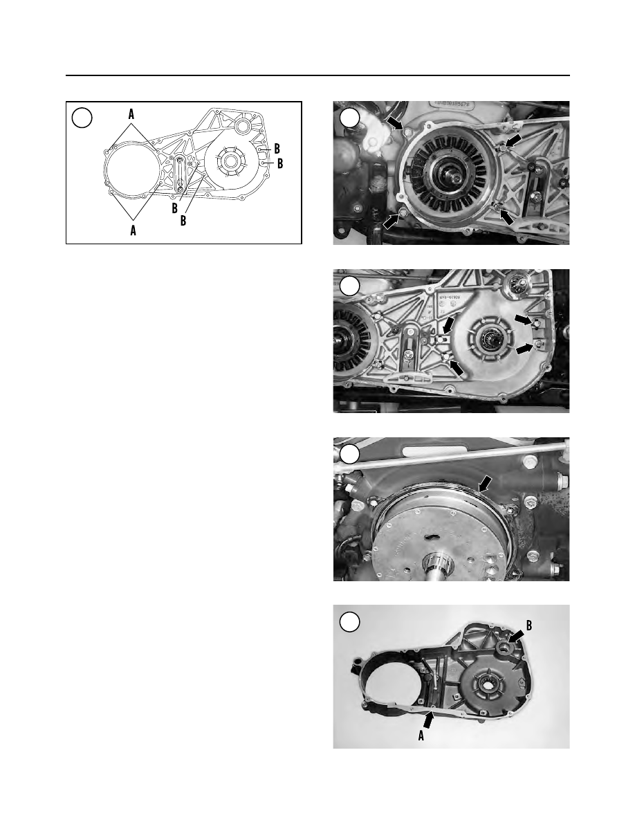
8. Remove all eight bolts securing the housing to the en-
gine and the transmission. Discard all lockwashers as new
ones must be installed.
9. Remove the starter jackshaft assembly from the hous-
ing as described in this chapter.
10. Tap the primary housing loose.
11. Remove the housing from the engine, transmission
and gearshift shaft.
12. Remove the O-ring (Figure 76) from the engine
crankcase shoulder.

Inspection

1. Remove all gasket residue from the housing gasket
surfaces (A, Figure 77).
2. Clean the housing in solvent and dry it thoroughly.
3. Check the housing (Figure 78) for cracks or other
damage.
4. Check the starter jackshaft oil seal for excessive wear
or damage. If necessary, replace the oil seal as follows:

a. Note the direction the oil seal lip faces in the housing.
b. Pack the new oil seal lips with grease.
c. Pry the oil seal out of the inner primary housing.
d. Carefully drive the

new

oil seal into the housing un-

til it seats against the housing shoulder.

5. Inspect the starter jackshaft bushing (B, Figure 77) for
wear, cracks or other damage. If necessary, replace the
bushing as follows:

a. Remove the bushing with a blind bearing removal

tool.

b. Clean the bushing bore in the housing.
c. Press the new bushing in until its outer surface is

flush with the edge of the bushing bore.

6. Turn the inner bearing race (Figure 79) by hand. Re-
place the bearing as follows:

a. Remove the oil seal (Figure 80) as described in

Step 7.

b. Remove the inner and outer bearing snap rings.

222

CHAPTER FIVE

73

74

75

76

77

c. Support the housing and press the bearing out.
d. Install the outer snap ring (clutch side). Make sure

the snap ring is correctly seated in the groove.

CAUTION

When pressing the bearing into the housing,
support the outer snap ring. The force re-
quired to press the bearing into the inner
primary housing may force the snap ring out
of its groove, damaging the housing.

e. Support the inner housing and outer snap ring.
f. Press the bearing into the inner housing until it seats

against the snap ring.

g. Install the inner snap ring. Make sure the snap ring

is seated correctly in the groove.

h. Install a

new

oil seal as described in Step 7.

7. Inspect the primary housing oil seal (Figure 80) for
excessive wear, tearing or other damage. If necessary, re-
place the oil seal as follows:

a. Remove the oil seal with a wide-blade screwdriver.
b. Clean the oil seal bore.
c. Pack the oil seal lip with a waterproof bearing

grease.

d. Position the oil seal with its closed side facing out.

Press the

new

oil seal in until its outer surface is

flush with the edge of the bearing bore.

8. Check the primary chain adjuster rack screws (Figure
81
) for looseness. Tighten the screws if necessary.

Installation

1. Thoroughly clean the

outer surface

of the eight bolt

holes of the inner cover. Apply a light coat of black RTV
sealant to the inner surfaces.
2. Install the

new

O-ring (Figure 76) onto the engine

crankcase shoulder.
3. To prevent the transmission mainshaft splines from
damaging the inner cover oil seal as it passes over, wrap
the mainshaft splines with tape.
4. If removed, install the drive belt prior to installing the
inner housing.
5. Align the inner housing with the engine and transmis-
sion, and install it. Push the inner housing on until it stops.
6. Install all eight bolts and

new

lockwashers securing the

inner housing to the engine and the transmission.
7. Tighten the inner housing bolts in the following order.

a. Tighten the four primary housing-to-engine mount-

ing bolts (Figure 74) to 17-21 ft.-lb. (23-29 N•m).
Bend the lockwasher tabs against the four bolt
heads.

b. Tighten the four primary housing-to-transmission

mounting bolts (Figure 75) to 17-21 ft.-lb. (23-29

CLUTCH AND PRIMARY DRIVE

223

5

78

79

80

81

N•m). Bend the lockwasher tabs against the four
bolt heads.

8. Install the starter jackshaft as described in this chapter.

9. Install the starter motor as described in Chapter Eight.

10. Install the compensating sprocket, primary chain and
clutch assembly as described in this chapter.

11. Install the primary chaincase cover as described in
this chapter.

12. Connect the negative battery cable as described in
Chapter Eight.

STARTER JACKSHAFT

Removal

Refer to Figure 82.

224

CHAPTER FIVE

82

STARTER JACKSHAFT

1. Bolt
2. Lockplate
3. Thrust washer

(with seal insert)

4. Pinion gear
5. Spring
6. Snap ring
7. Coupling
8. Jackshaft
9. Snap ring

10. Coupling

Snap ring groove

Snap ring groove

83

84

85

86

NOTE

On models so equipped, always disarm the
optional TSSM security system prior to dis-
connecting the battery or the siren will sound.

1. Disconnect the negative battery cable as described in
Chapter Eight.
2. Remove the primary chaincase cover as described in
this chapter.

NOTE

The pinion gear components (1-5,

Figure

82

) can be removed with the clutch/pri-

mary chain assembly in place. If only
these parts require service, do not per-
form Step 3.

3. Remove the compensating sprocket, primary chain
and clutch assembly as described in this chapter.
4. Straighten the tab on the lockplate (Figure 83).
5. Wrap the pinion gear with a cloth to protect the finish,
then secure it with pliers (A, Figure 84).
6. Loosen and remove the bolt (B, Figure 84), lockplate
and thrust washer from the starter jackshaft assembly and
the end of the starter motor.
7. Remove the pinion gear (Figure 85) and spring from
the jackshaft.
8. Remove the jackshaft assembly and the coupling from
the inner housing.

Inspection

1. Clean the jackshaft assembly (Figure 86) in solvent
and dry it with compressed air.
2. Check the snap ring installed in each coupling (Figure
87
) and (Figure 88). Replace any loose or damaged snap
rings.
3. Replace all worn or damaged parts.

Installation

NOTE

Before installing the coupling in Step 4,
note the snap ring (

Figure 87

) installed in-

side the coupling. The coupling side with
the snap ring closest to its end slides over
the jackshaft.

1. Install the jackshaft (Figure 89) into the housing. Push
it in until it stops.
2. Position the coupling with its counterbore facing to-
ward the jackshaft and install the coupling (Figure 90)
into the housing bushing.
3. Install the spring (Figure 91) onto the jackshaft.

CLUTCH AND PRIMARY DRIVE

225

5

87

88

89

90

4. Install the pinion gear (Figure 92) onto the jackshaft.

5. Push in on the pinion gear (A, Figure 93) and install
the bolt, lockplate and thrust washer (B) onto the
jackshaft.

6. Push the assembly on until it bottoms.

7. Align the lockplate tab with the thrust washer, then in-
sert the tab into the notch in the end of the jackshaft.

8. Screw the bolt into the starter motor shaft by hand.

9. Wrap the pinion gear with a cloth to protect the finish,
then secure it with pliers (A, Figure 84).

10. Tighten the starter jackshaft bolt (B, Figure 84) to
84-108 in.-lb. (9-12 N•m). Bend the outer lockplate tab
against the bolt head (Figure 83).

11. To ensure the components have been installed cor-
rectly, perform the following:

a. Install the clutch shell onto the transmission

mainshaft.

b. With the starter motor not engaged, the pinion gear

(A, Figure 94) must not engage the clutch shell gear
(B).

c. To check for proper engagement, pull out on the

pinion gear and engage it with the clutch shell gear.
Then rotate the clutch shell in either direction and
make sure the pinion gear rotates with it.

d. If engagement is incorrect, remove the clutch shell

and correct the problem.

e. Remove the clutch shell.

12. Install the compensating sprocket, primary chain and
clutch assembly as described in this chapter.

13. Install the primary chaincase cover as described in
this chapter.

14. Connect the negative battery cable as described in
Chapter Eight.

226

CHAPTER FIVE

91

92

93

94

95

CLUTCH CABLE REPLACEMENT

1. Before removing the clutch cable, make a drawing of
its routing path from the handlebar to the transmission
side door.

2. Disconnect the clutch cable from the clutch release
mechanism (Figure 95) as described under

Transmission

Side Cover

in Chapter Six.

3. Remove the snap ring from the base of the clutch lever
pivot pin.

4. Remove the pivot pin and slide the clutch lever out its
perch.

5. Remove the plastic anchor pin (Figure 96) and discon-
nect the clutch cable from the lever.

6. Check the clutch lever components (Figure 97) for
worn or damaged parts.

7. Make sure the anti-slack spring screw (Figure 98) on
the bottom of the clutch lever is tight.

8. Remove the screw and bracket (Figure 99) securing the
clutch cable to the frame front down tube cross member.

9. Carefully pull the clutch cable down through the steer-
ing stem upper and lower brackets (Figure 100, typical)
and out from behind the voltage regulator/rectifier (Fig-
ure 101
, typical).

CLUTCH AND PRIMARY DRIVE

227

5

96

97

98

99

100

101

10. Route the new clutch cable from the handlebar to the
transmission side cover following the drawing made in Step 1.
11. Fit the clutch cable into its lever and secure it with the
plastic anchor pin (Figure 96).
12. Slide the clutch lever into the perch and install the
pivot pin.

13. Secure the pivot pin with the snap ring.

14. Reconnect the clutch cable to the clutch release
mechanism as described under

Transmission Side Cover

in Chapter Six.

15. Adjust the clutch as described in Chapter Three.

Table 1  CLUTCH  SPECIFICATIONS AND SPROCKET SIZES

Item

Specification

Clutch type

Wet, multiplate disc

Clutch lever free play

1/16-1/8 in. (1.6-3.2 mm)

Clutch friction plate thickness

service limit

0.143 in. (3.62 mm)

Clutch plate warp

service limit

0.006 in. (0.15 mm)

Compensating sprocket

25 teeth

Clutch sprocket

36 teeth

Transmission sprocket

32 teeth

Table 2  CLUTCH AND PRIMARY CHAINCASE TORQUE SPECIFICATIONS

Item

ft.-lb.

in.-lb.

N•m

Diaphragm spring bolts

90-108

10-12

Clutch hub nut*

70-80

95-108

Compensating sprocket nut*

150-165

203-224

Primary chaincase cover bolts

108-120

12-14

Primary chaincase inspection cover

long and short screws

84-108

9-12

Primary chaincase

housing-to-engine and transmission bolts

17-21

23-29

Starter jackshaft bolt

84-108

9-12

*Apply threadlocking compound

Table 3  COMPENSATING SPROCKET ALIGNMENT SPACERS

Spacer part No.

in.

mm

35850-84

0.010

0.25

35851-84

0.020

0.51

35852-84

0.030

0.76

24032-70

0.060

1.52

24033-70

0.090

2.29

24034-70

0.120

3.05

24035-70

0.150

3.81

24036-70

0.180

4.57

24037-70

0.210

5.33

228

CHAPTER FIVE

CHAPTER SIX

TRANSMISSION

This chapter covers procedures for the transmission and

shift linkage. Specifications are in Tables 1-3 at the end of
the chapter. Special tool requirements are described in the
procedures. All of the special tools used in this manual and
their part numbers are listed in Table 12 of Chapter One.

All models are equipped with a five-speed transmission

that is separate unit attached to the rear of the engine. The
transmission shaft and shifter assemblies can be serviced
with the transmission case mounted in the frame.

SHIFTER ASSEMBLY

The shifter assembly (Figure 1) consists of the external

shift linkage and internal shift cam and shift arm compo-
nents. The internal components can be serviced with the
transmission case installed in the frame by removing the
top cover.

If a shifting problem is encountered, refer to the trou-

bleshooting procedures in Chapter Two and eliminate all
clutch and shifter mechanism possibilities

before

consid-

ering transmission repairs. Improper clutch adjustment
(Chapter Three) is often a cause of poor shifting.

Shift Linkage Adjustment

The shift linkage assembly connects the transmission

shift rod lever to the foot-operated shift levers. The shift
linkage does not require adjustment unless it is replaced or
the transmission gears do not engage properly.

CAUTION

On FLST models, the heal shift lever must
never touch the footboard when shifting
gears. To ensure proper gear engagement
and avoid possible transmission damage,
there must be a minimum clearance of 3/8
in. (9.5 mm) between the bottom of the heal
shift lever and the top of the footboard. If the
clearance is not correct, reposition the heal
shift lever as described under

External

Shift Mechanism

in this chapter.

NOTE

On models so equipped, always disarm the
optional TSSM security system prior to dis-
connecting the battery or the siren will sound.

1. Disconnect the negative battery cable as described in
Chapter Eight.

6

NOT

E: R

efer t

o the

Supp

leme

nt

at th

e ba

ck o

f this

man

ual

for

inform

ation

uniq

ue to

2004

-2005

mod

els,

inclu

ding

Scre

amin

Eagle

mod

els.

230

CHAPTER SIX

1

SHIFTER ASSEMBLY

1. Snap ring
2. Bearing
3. Bolt
4. Support—right side
5. Shift cam
6. Support—left side
7. Locating dowel
8. Cam follower
9. Sleeve

10. Spring
11. Bolt
12. Shift fork shaft
13. Shift fork No. 3
14. Shift fork No. 2

15. Shift fork No. 1
16. Set screw
17. Shift peg
18. Shift lever (FLST)
19. Bolt
20. Bolt
21. Washer
22. Outer shift lever

(FXST)

23. Shift rod
24. Shift lever
25. Washer
26. Acorn nut
27. O-ring

28. Bearing sleeve
29. Nylon washer
30. Shift rod lever
31. Bolt
32. Oil seal
33. Washer
34. Retaining ring
35. Centering pin
36. Transmission case
37. Spring
38. Shift lever

centering pin

39. Shift shaft lever/pawl

2. Loosen the two shift linkage rod locknuts (A, Figure 2).

3. Remove the acorn nut (Figure 3) and washers securing
the shift linkage rod to the inner shift lever.

4. Turn the shift linkage rod (B, Figure 2) as necessary to
change the linkage adjustment.

5. Reconnect the shift linkage rod to the front shift lever and
tighten the locknuts to 20-24 ft.-lb. (27-32 N•m).

6. Recheck the shifting. Readjust if necessary.

7. If this adjustment does not correct the shifting, check
the shift linkage for interference problems.

EXTERNAL SHIFT MECHANISM

Removal/Installation

Refer to Figure 1.

NOTE

On models so equipped, always disarm the
optional TSSM security system prior to dis-
connecting the battery or the siren will sound.

1. Disconnect the battery negative lead as described in
Chapter Eight.

2. Support the motorcycle with the front wheel off the
ground. See

Motorcycle Stands

in Chapter Eight.

3. On models so equipped, remove the front left side foot-
board as described in Chapter Fourteen.

4A. On FXST models, perform the following:

a. Make an alignment mark on the outer shift lever and

the end of the shift shaft lever.

b. Remove the clamp bolt and remove the outer shift

lever.

4B. On FLST models, perform the following:

a. Make an alignment mark on the heal shift lever and

the end of the shift shaft lever.

b. Remove the clamp bolt and remove the heal shift le-

ver.

c. Make an alignment mark on the toe shift lever that

relates to the end of the shift lever shaft.

d. Remove the clamp bolt and remove the toe shift le-

ver.

5. Remove the nylon washer from the inner shift lever.

6. Remove the acorn nut (Figure 3) and washers secur-
ing the shift linkage rod to the inner shift lever.

7. Remove the jiffy stand and mounting bracket assembly
as described in Chapter Fourteen.

8. Remove the primary chaincase assembly as described
in Chapter Five.

9. Remove the clamp bolt securing the shift rod lever
(Figure 4) to the transmission case.

10. Remove the shift rod lever, shift rod, inner and outer
shift levers (Figure 5) and shift lever shaft as an assembly.

11. Install by reversing these removal steps. Tighten the
clamp bolts securely.

TRANSMISSION TOP COVER

The transmission top cover assembly can be serviced

with the transmission case installed in the frame.

TRANSMISSION

231

6

2

3

4

Removal/Installation

1. Remove the exhaust system as described in Chapter
Seven.
2. Remove the battery as described in Chapter Eight.
3. Remove the oil tank (A, Figure 6) and oil lines as de-
scribed in Chapter Four.
4. Disconnect the wire from the neutral indicator switch.
5. Disconnect the vent hose from the top cover or the fit-
tings.

6. Remove the bolts and washers securing the transmis-
sion cover (B, Figure 6) to the transmission case. Remove
the top cover and the gasket.

7. Remove the gasket residue from the transmission
cover and transmission case gasket surfaces.

8. Install a

new

gasket onto the transmission case.

9. Install the transmission top cover, three bolts and
washers. Tighten the bolts in a crisscross pattern to 84-108
in.-lb. (9-12 N•m).

232

CHAPTER SIX

5

6

7

SHIFT CAM ASSEMBLY

1. Snap ring
2. Ball bearing
3. Support—right side
4. Shift cam
5. Support—left side

6. Retaining ring
7. Detent follower
8. Sleeve
9. Spring

10. Pivot screw

10. Reconnect the vent hose to the fitting and install a

new

hose clamp.

11. Connect the wire to the neutral indicator switch.
12. Install the oil tank as described in Chapter Four.
13. Install the battery as described in Chapter Eight.
14. Install the exhaust system as described in Chapter
Seven.

SHIFT CAM

The shift cam assembly (Figure 7) can be serviced with

the transmission case installed in the frame by removing
the battery, oil tank and transmission top cover.

Removal

1. Remove the transmission top cover as described in this
chapter.

2. Remove the shift cam support block mounting bolts
(Figure 8).
3. Lift the shift cam pawl off the cam pins to free the as-
sembly.
4. Carefully lift the shifter cam assembly up and out of
the transmission case.
5. Remove the four dowel pins from the transmission case.

Installation

1. Install the four dowel pins into the transmission case.
2. Lift the shift cam pawl up out of the way.
3. Carefully install the shift cam assembly into the transmis-
sion case. Align the shift fork pins with the shift cam slots.
4. Lower the shift cam pawl and engage it with the cam
pins.
5. Install the shift cam support block mounting bolts.
Tighten the bolts in a crisscross pattern to 84-108 in.-lb.
(9-12 N•m).
6. Install the transmission top cover as described in this
chapter.

Disassembly

1. On the right side, perform the following:

a. Slide the right side support block (A, Figure 9) off

the shift cam.

b. Remove the snap ring (B, Figure 9) and withdraw

the bearing (C) from the support block.

2. On the left side, perform the following:

a. Remove the small retaining ring (A, Figure 10)

from the shifter cam.

TRANSMISSION

233

6

8

9

10

b. Slide the left side support block (B, Figure 10) off

the shifter cam.

c. Remove the large retaining ring (C, Figure 10) and

withdraw the bearing from the support block.

3. To remove the detent follower, unscrew the pivot bolt
(A, Figure 11). Remove the spring (B), spring sleeve (C)
and the detent follower (D).

Inspection

1. Clean all parts, except the support block bearings, in
solvent and dry them thoroughly.
2. Check the shift cam grooves (Figure 12) for wear or
roughness. Replace the shift cam if the groove profiles are
excessively worn or damaged.
3. Check the shift cam ends where the cam contacts the
bearings. If the ends are worn or damaged, replace the
shift cam and both support block bearings.
4. Check the support block bearings for excessive wear,
cracks or other damage. See Figure 13, typical. If neces-
sary, refer to

Basic Service Methods

in Chapter One to re-

place the bearings

.

5. Check the support blocks for wear, cracks or other
damage. Replace the support blocks if necessary.

Assembly

1. Coat all bearing and sliding surfaces with assembly oil.
2. Install the detent follower as follows:

a. Slide the spring sleeve (C, Figure 11) into the

spring (B).

b. Insert the pivot bolt (A, Figure 11) through the

spring and sleeve.

c. Correctly position the detent follower onto the bolt

and place the spring end over the detent follower.

d. Install the detent follower assembly onto the right

side support and insert the spring’s other end into
the receptacle in the right side support. Screw the
bolt into place and tighten it to 84-108 in.-lb. (9-12
N•m).

3. On the left side, perform the following:

a. Position the bearing with the manufacturer’s num-

bers facing out. Install the bearing into the support
block.

b. Position a

new

snap ring (C, Figure 10) so the larger

tab will be on the right side when looking at the end
of the support block. Install the snap ring.

c. Make sure the snap ring is correctly seated in the

groove.

d. Slide the left side support block (B, Figure 10) onto

the shifter cam.

e. Install a

new

small retaining ring (A, Figure 10)

onto the shifter cam.

f. Make sure the retaining ring is correctly seated in

the groove.

4. On the right side, perform the following:

a. Position the bearing with the manufacturer’s numbers

facing out. Install the bearing into the support block.

234

CHAPTER SIX

12

13

11

b. Position a

new

snap ring (B, Figure 9) with the bev-

eled side facing out when looking at the end of the
support block. Install the large retaining ring.

c. Make sure the snap ring is correctly seated in the

groove.

d. Slide the right side support block (A, Figure 9) onto

the shifter cam.

SHIFT ARM ASSEMBLY

Removal/Disassembly

Refer to Figure 14.

1. Remove the transmission side door assembly as de-
scribed in this chapter.
2. Make an alignment mark on the shift rod lever and the
end of the shift shaft lever/pawl.
3. Remove the clamp bolt and remove the shift rod lever
from the shift shaft lever/pawl.
4. Remove the snap ring and washer from the shift lever
shaft.
5. Withdraw the shift shaft lever/pawl, sleeve and spring
from the inner surface of the transmission case.

Inspection

1. Check the shift pawl for wear. Replace the pawl if it is
damaged.
2. Check the springs for wear or damage.
3. Check the shift shaft lever for wear or damage. Check
the end splines for wear or damage.
4. Check the shift rod lever for wear or damage. Check
the internal splines for wear or damage.

Assembly/Installation

1. Check that the sleeve is still in place in the transmis-
sion case.
2. Slide the shift shaft lever spring over the shift shaft lever.
Align the opening on the spring with the tab on the lever.
3. Place the spring on the shift shaft lever/pawl.
4. Install the shift shaft lever assembly into the transmis-
sion case.
5. Align the spring with the screw in the case (Figure 15).
6. Install the washer and snap ring onto the shaft. Make
sure the snap ring is correctly seated in the shaft.
7. Refer to the alignment marks made in Step 1 of

Re-

moval/Disassembly

and instal the shift rod lever onto the

end of the shift shaft lever/pawl. Push it on until the bolt
hole aligns with the shaft lever/pawl groove.
8. Install the clamp bolt and tighten it to 18-24 ft.-lb.
(24-30 N•m).
9. Install the transmission side door assembly as de-
scribed in this chapter.

SHIFT FORKS

The shift forks can be serviced with the transmission

case installed in the frame by removing the battery, oil
tank and transmission top cover.

TRANSMISSION

235

6

15

14

SHIFT ARM ASSEMBLY

1. Spring
2. Washer
3. Screw
4. Clamp bolt
5. Shift shaft lever/pawl
6. Sleeve
7. Spring
8. Oil seal
9. Washer

10. Snap ring
11. Shift rod lever

Removal

Refer to Figure 1.
1. Remove the transmission top cover as described in this
chapter.
2. Remove the shift cam as described in this chapter.
3. Remove the transmission side cover as described in
this chapter.

NOTE

Use a waterproof felt-tip pen or scribe to
mark the installed position of each shift fork
in the transmission (

Figure 16

). All three

shift forks are unique and must be rein-
stalled in the correct position.

4. Slide the shift shaft (A, Figure 17, typical) out of the
transmission case and remove the shift forks (Figure 18)
from the transmission case.

Inspection

1. Inspect each shift fork (Figure 19) for excessive wear or
damage. Replace worn or damaged shift forks as required.
2. Measure the thickness of each shift fork finger (A, Fig-
ure 20
) where it contacts the sliding gear groove (Figure
21
). Replace any shift fork with a finger thickness worn to
the specification in Table 2.
3. Check the shift forks for arc-shaped wear or burn
marks (B, Figure 20). Replace damaged shift forks.
4. Roll the shift fork shaft on a flat surface and check for
bends. Replace the shaft if it is bent.

236

CHAPTER SIX

16

17

18

Shift shaft

Front

No. 1

No. 2

No. 3

No. 1

No. 2

No. 3

19

5. Install each shift fork on the shift shaft. The shift forks
must slide smoothly with no binding or roughness (Fig-
ure 22
).

Assembly

Refer to Figure 23 to identify the transmission gears.

1. Coat all bearing and sliding surfaces with assembly oil.
2. To install the shift forks and shaft (Figure 16), perform
the following:

a. Insert the No. 1 shift fork into the mainshaft first

gear groove.

b. Install the No. 2 shift fork into the countershaft third

gear groove.

c. Install the No. 3 shift fork into the mainshaft second

gear groove.

3. Insert the shift shaft (A, Figure 17) through each of the
three shift forks and into the transmission case.
4. Install the transmission side door as described in this
chapter.
5. Make sure the shift forks move smoothly when shift-
ing the gears by hand.
6. Install the shift cam as described in this chapter.

TRANSMISSION SIDE DOOR AND

TRANSMISSION SHAFT ASSEMBLIES

The transmission side door and transmission shaft as-

semblies can be serviced with the transmission case in-
stalled in the frame.

The following special tools are used during disassem-

bly and assembly:

TRANSMISSION

237

6

20

21

22

23

4th

1st 3rd

2nd 5th

Countershaft

Mainshaft


Content      ..     17      18      19      20     ..