Harley Davidson Softail 2000-2005. Service manual - page 17
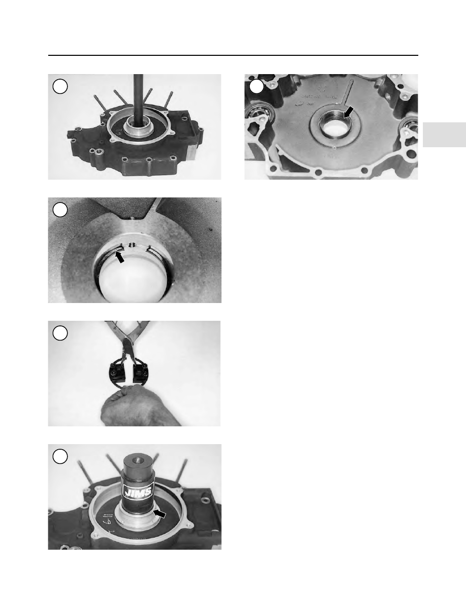
a. Place the crankcase on a workbench with the out-
board side facing up.
b. With the gap of the lock ring at the 12 o’clock posi-
tion, install the special tool clamps onto each side of
the lock ring at the 10 o’clock and 2 o’clock posi-
tions.
c. Securely tighten the 9/16 in. Allen screws securing
the clamps to the lock ring.
d. Use snap ring pliers to compress the lock ring and
withdraw it from the crankcase groove.
e. Remove the clamps from the old lock ring and in-
stall them onto the new lock ring.
f. Squeeze the pliers (Figure 351) and insert the lock
ring into the crankcase groove.
g. Make sure the lock ring gap is centered with the
crankcase oil hole.
NOTE
Install both races with their larger diameter
sides facing out. Install the bearing races
with the same tool used to remove the old
ones.
20. Apply clean engine oil, or press lube, to the bearing
receptacles in the crankcase and to the outer surface of the
inner bearing races.
NOTE
The large end of the installer base must con-
tact the crankcase outer surface as shown in
Figure 352
.
21. Place the installer base on the press bed with the large
end facing up.
22. Install the inboard outer race onto the crankcase re-
ceptacle (Figure 353).
23. Position the crankcase with the inboard surface fac-
ing up.
24. Install the crankcase onto the installer base so the
crankcase retaining ring rests on top of the installer base.
ENGINE
181
4
350
351
352
353
349