Harley Davidson Softail 2000-2005. Service manual - page 16
 

  Главная      Harley Davidson     Harley Davidson Softail 2000-2005. Service manual


Search            copyright infringement  


Content      ..     14      15      16      17     ..


Harley Davidson Softail 2000-2005. Service manual - page 16


9. Install the

install side

of the driver (Figure 279)

through the bushing and into the support tool until the
driver contacts the edge of the bushing.
10. Press the bushing into the support plate until the
driver collar contacts the support plate.
11. Remove the special tools and the support plate from
the press bed.

Camshaft Bearing Replacement

Ball bearings

A hydraulic press, camshaft bearing puller (JIMS part

No 1280), and camshaft remover and installer (JIMS part
No. 1277) are required to remove and install the camshaft
ball bearings.
1. Install the camshaft bearing puller tool onto the cam-
shaft ball bearing (Figure 280) and remove the camshaft
ball bearing following the manufacturer’s instructions.
2. Repeat Step 1 for the other camshaft bearing.

NOTE

The ball bearing is installed in the camshaft
support plate, not on the camshaft(s).

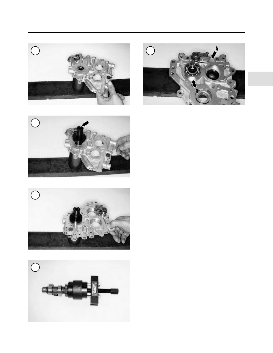
3. Install the ball bearing(s) into the camshaft support
plate using the camshaft remover and installer as follows:

a. Place the support block on the press bed.
b. Place the camshaft support plate onto the support

block (A, Figure 281). Make sure the support plate
is indexed correctly into the support block.

c. Apply a light coat of clean engine oil, or press lube,

to the outer surface of the ball bearing and to the
support plate bearing receptacle.

d. Place the ball bearing onto the support plate (B, Fig-

ure 281).

e. Install the bearing pilot (Figure 282) into the ball

bearing.

ENGINE

165

4

277

278

279

280

281

f. Press the bearing straight into the support plate until

it bottoms.

g. Remove the pilot from the bearing and remove the

support plate from the press bed.

Needle bearings

The inner cam bearing installer (JIMS part No. 1278) is

used in the following procedure:

NOTE

The camshaft needle bearings (

Figure 283

)

can be removed with the engine mounted in
the frame after the camshaft support plate is
removed.

NOTE

Replace both needle bearings as a set even if
only one requires replacement.

1. Remove the camshaft support plate assembly from the
engine as described in this chapter.

2. Install the puller portion of the tool set (A, Figure 284)
part way into the needle bearing. Install a small hose
clamp (B) onto the end that is closest to the needle bearing
and tighten it. This closes the end of the tool so it can pass
through the needle bearing. Push the puller all the way
through the needle bearing and remove the hose clamp.

3. Assemble the remainder of the tool components onto
the puller portion (Figure 285) following the manufac-
turer’s instructions.

4. Place a 5/8 in. wrench on the flats of the puller (A, Fig-
ure 286
).

5. Place a 1 1/8 in. wrench, or an adjustable wrench, on
the large nut (B, Figure 286).

CAUTION

Do not turn the 5/8 in. wrench as this will
damage the special tool and the crankcase
receptacle.

6. Hold onto the 5/8 in. wrench (A, Figure 286) to keep
the puller from rotating. Turn the 1 1/8 in. wrench B, Fig-
ure 286
)

clockwise

on the large nut. Tighten the large nut

and pull the needle bearing out of the crankcase recepta-
cle.

7. Disassemble the special tool and remove the needle
bearing from it.

8. Repeat Steps 2-7 for the other needle bearing.

9. Apply a light coat of clean engine oil, or press lube, to
the outer surface of the

new

needle bearings and to the

crankcase needle bearing receptacles (Figure 287).

166

CHAPTER FOUR

282

283

284

285

NOTE

The following photographs are shown with
the crankcase disassembled to better illus-
trate the steps.

10. Apply a light coat of clean engine oil to the threads of
the screw portion and to the installer plate.
11. Insert the screw portion of the special tool part way
into the installer plate.
12. Push the installer onto the screw until it locks into
place.
13. Position the new bearing with the manufacturer’s
marks facing out on the installer (Figure 288).
14. Install the installer plate onto the crankcase, aligning
the tool to the bearing receptacle (A, Figure 289).
15. Install the thumb screws through the installer plate
(B, Figure 289) and onto the crankcase threaded holes.
Tighten the thumb screws securely.
16. Slowly tighten the screw until the bearing starts to en-
ter the crankcase receptacle. Continue to tighten it until
the installer contacts the crankcase surface. This will cor-
rectly position the needle bearing within the crankcase.
17. Remove the special tools.
18. Repeat Steps 10-17 for the other needle bearing.

Oil Pressure Relief Valve Removal/Installation

NOTE

This procedure is shown with the camshaft as-
sembly removed to better illustrate the steps.

1. Remove the camshaft support plate assembly from the
engine as described in this chapter.
2A. If the camshaft assembly is still in place, secure the
camshaft support plate in a vise with soft jaws.
2B. If the camshaft assembly has been removed, place the
camshaft support plate on a piece of soft wood.
3. Use a 1/8 in. punch to drive out the roll pin (Figure
290
) securing the valve body and spring. Discard the roll
pin (A, Figure 291).
4. Remove the valve body (B, Figure 291) and spring (C)
from the bypass port of the camshaft support plate.
5. Inspect the valve body, spring and bypass port (Figure
292
) for wear or damage. Replace as necessary.
6. Apply a light coat of clean engine oil to the bypass port
and to the valve body.
7. Position the valve body (A, Figure 293) with the
closed end going into the bypass port first.
8. Install the spring (B, Figure 293) into the valve body.
9. Push the valve body and spring into the bypass port,
hold them in place and install a

new

roll pin (Figure 294).

Tap the roll pin in until it bottoms (Figure 290).

ENGINE

167

4

286

287

288

289

Cleaning Plug Removal/Installation

NOTE

This procedure is shown with the camshaft as-
sembly removed to better illustrate the steps.

1. Remove the camshaft support plate assembly from the
engine as described in this chapter.

2A. If the camshaft assembly is still in place, secure the
camshaft support plate in a vise with soft jaws.

2B. If the camshaft assembly has been removed, place the
camshaft support plate on piece of soft wood.

3. Use a pair of pliers to carefully remove the cleaning
plug (Figure 295) from the camshaft support plate. Re-
move the O-ring.

4. Thoroughly clean the cleaning plug receptacle and
support plate in solvent. Dry them with compressed air.

5. Apply low-pressure compressed air to the cleaning
plug receptacle (Figure 296) to blow out any debris.
Make sure the oil hole is clear.

6. Install a

new

O-ring onto the cleaning plug and install

the cleaning plug. Press it in until it bottoms.

168

CHAPTER FOUR

290

291

292

293

294

295

Camshaft Primary and Secondary Chain
Tensioner Removal/Inspection/Installation

NOTE

The following illustrations show the pri-
mary chain tensioner. They also apply to the
secondary chain tensioner.

1. Remove the camshaft primary and/or secondary chain
as described in this chapter.

2. Remove the snap ring (Figure 297) securing the chain
tensioner to the mounting post.

3. Slide the chain tensioner (A, Figure 298) off the
mounting post.

4. Inspect the chain tensioner pad (A, Figure 299) for
wear. If the pad surface is worn halfway through (A, Fig-
ure 
300) or chipped (B), replace the assembly.

5. Check the spring (B, Figure 299) for sagging or dam-
age. Replace the assembly if necessary.

6. Install the chain tensioner onto the mounting post and
insert the spring end into the receptacle in the cover (B,
Figure 298). Push the chain tension on until it bottoms.

7. Install a

new

snap ring (Figure 301). Make sure it is

correctly seated in the mounting post groove.

ENGINE

169

4

296

297

298

299

300

301

CRANKCASE AND CRANKSHAFT

Disassembly

A twin cam 88B engine stand (JIMS part No. 1142),

base stand (JIMS part No. 1138) and crankcase assembly
removing tool (JIMS part No. 1047-TP) are used in some
of the following procedures:

CAUTION

On 2000-2002 models, prior to disassem-
bling the crankcase, measure the crankshaft

end play as described in

Crankshaft End

Play Inspection.

Refer to Figure 302 and Figure 303.

1. Remove the engine from the frame as described in this
chapter.

CAUTION

Do not lift the crankcase assembly by the
cylinder studs. Bent or damaged cylinder
studs may cause the engine to leak oil.

170

CHAPTER FOUR

302

CRANKCASE ASSEMBLY (2000-2002)

1. Crankshaft assembly
2. Connecting rod bushing
3. Screw
4. Bearing retainer plate
5. Needle bearing—camshaft
6. Dowel pin
7. Right side main bearing
8. Plug
9. O-ring

10. Piston cooling jet
11. Screw
12. Locating dowel
13. O-ring
14. Crankcase assembly
15. Locating dowel
16. O-ring
17. Bolt
18. Bearing
19. Bearing race
20. Lock ring
21. Spacer ring
22. Bearing race
23. Bearing
24. Shim
25. Sprocket shaft spacer
26. Left side main

bearing assembly

2. Remove the following components as described in this
chapter:

a. Cylinder heads and cylinders.

b. Pistons.

c. Pushrods and valve lifters.

d. Camshaft assembly.

e. Oil pump.

f. Alternator rotor and stator assembly (Chapter Eight).

NOTE

Leave the bolts for the left side off so the
case halves can be separated in the follow-
ing steps.

3. If the special tool is available, attach the crankcase as-
sembly to an engine stand (Figure 304) following the
manufacturer’s instructions.

4. Secure the engine base stand to the workbench.

5. Using the torque pattern shown in Figure 305, loosen
the bolts in two to three stages and remove them from the
left side of the crankcase (Figure 306).

6. Place the crankcase assembly on wooden blocks with
the camshaft cover (left side) facing up. Use wooden
blocks thick enough so the right side of the crankshaft
clears the workbench surface.

ENGINE

171

4

303

CRANKCASE ASSEMBLY (2003)

1. Crankshaft assembly
2. Connecting rod bushing
3. Screw
4. Bearing retainer plate
5. Needle bearing—camshaft
6. Dowel pin
7. Right side main bearing
8. Plug
9. O-ring

10. Piston cooling jet
11. Screw
12. Locating dowel
13. O-ring
14. Crankcase assembly
15. Locating dowel
16. O-ring
17. Bolt
18. Thrust washer
19. Oil seal
20. Sprocket shaft spacer
21. Retaining ring
22. Bearing

7. Tap around the perimeter of the crankcase with a plas-
tic mallet and remove the left crankcase half (Figure
307
).
8. If the crankcase halves will not separate easily, per-
form the following:

a. Install a crankcase assembly removing tool (A, Fig-

ure 308) onto the left side of the crankcase follow-
ing the manufacturer’s instructions.

b. Apply clean engine oil, or press lube, to the end of

the center screw and install it into the tool.

CAUTION

Do not use a hand impact driver or air im-
pact wrench on the center screw. They will
damage the crankcase halves and the tool.

c. Slowly turn the center screw (B, Figure 308) with a

wrench 1/2 turn at a time. After each turn, tap on the
end of the center screw with a brass mallet to relieve
the stress on the center screw and the tool.

d. Repeat substep c until the center screw turns freely

and the crankcase halves begin to separate (C, Fig-
ure 308
).

e. If used, remove the crankcase from the engine

stand.

f. Separate the crankcase halves (Figure 309).
g. Remove the special tool from the left side crankcase

unless the crankshaft is going to be removed in Step
10.

9. Remove the locating dowels and O-rings (Figure 310)
from the right side crankcase.

CAUTION

On 2003 models, after the counterbalancer
assembly is removed, the crankshaft assem-
bly is no longer secure in the left side crank-
case. Be aware of this to avoid dropping the
crankshaft assembly.

10. Remove the counterbalancer assembly as described
under

Counterbalancer Assembly

in this chapter.

WARNING

Wear safety glasses to press out the crank-
shaft.

CAUTION

Do not drive the crankshaft out of the crank-
case with a hammer.

11A. On 2000-2002 models, if a hydraulic press is avail-
able, press the crankshaft out of the right crankcase half as
follows:

a. Support the right crankcase half on wooden blocks

in a press with the outer surface facing up.

172

CHAPTER FOUR

304

306

307

305

b. Center the press ram on the end of the crankshaft,

then press the crankshaft out of the right crankcase
half. Have an assistant support the crankshaft as it is
being pressed out.

c. Remove the crankshaft.

d. Remove the right crankcase half from the press bed

and place it on a workbench for further service.

11B. On 2000-2002 models, if a hydraulic press is not
available, perform the following:

a. Install a crankcase assembly removing tool onto the

left side of the crankcase following the manufac-
turer’s instructions (Figure 311).

b. Apply clean engine oil, or press lube, to the end of

the center screw and install it into the tool.

CAUTION

Do not use a hand impact driver or air im-
pact wrench on the center screw, as they will
damage the crankcase and the tool.

c. Secure the right side of the crankshaft with a

wrench (A, Figure 312) to prevent it from rotating
in the following step.

d. Slowly turn the center screw with a wrench (B, Fig-

ure 312) 1/2 turn at a time. After each turn, tap on
the end of the center screw with a brass mallet to re-
lieve the stress on the center screw and the tool.

e. Repeat substep d until the center screw pushes the

crankshaft out of the left side crankcase half.

f. Remove the special tool from the left side crankcase

half.

11C. On 2003 models, lift up and remove the crankshaft
assembly from the left side crankcase half.

12A. On 2000-2002 models, to remove the left side crank-
shaft outer roller bearing and oil seal assembly, perform
the following:

a. Place the left side crankcase on the workbench with

the outer surface facing up.

ENGINE

173

4

310

311

312

309

308

b. Carefully pry the sprocket shaft spacer out of the oil

seal.

c. Carefully pry the oil seal out of the crankcase using

a wide-blade screwdriver. Support the screwdriver
with a rag to prevent damage to the crankcase.

d. Lift the outer roller bearing from the crankcase.

12B. On 2003 models, to remove the left side crankshaft
bearing refer to

Left Side Main Bearing Assembly Re-

placement (2003 Models)

in this section.

Crankcase Cleaning and Inspection

1. Clean both case halves in solvent and dry them with
compressed air.
2. Remove all gasket sealer residue from all mating sur-
faces.
3. Apply a light coat of oil to the races to prevent rust.
4. Inspect the right side (Figure 313) and left side (Fig-
ure 314
) case halves for cracks or other damage. Espe-
cially in the lower areas.
5. Inspect all machined surfaces (Figure 315) for burrs,
cracks or other damage.
6. Inspect the case studs (Figure 316) for bending, cracks
or other damage. If necessary, replace studs as described
under

Cylinder Stud Replacement

in this section.

7A. On 2000-2002 models, inspect the left side main bear-
ing races. Refer to Figure 317 for the outer bearing race
and Figure 318 for the inner bearing race. Also, check the
roller bearings for wear or damage. The bearings should
turn smoothly with no roughness. If any of these parts are
worn, replace the bearing assembly as described under

Left

Side

Main

Bearing

Assembly

Replacement

(2000-2002 Models)

in this section.

7B. On 2003 models, inspect the left side assembled roller
bearing for wear or damage. The bearing should turn
smoothly with no roughness. If worn, replace the assem-
bled bearing as described under

Left Side Main Bearing

Assembly Replacement (2003 Model)

in this section.

174

CHAPTER FOUR

313

314

315

316

317

8. Inspect the right side main bearing (Figure 319) for
wear or damage. The bearing should turn smoothly with
no roughness. If it is damaged, replace the bearing assem-
bly as described under

Right Side Main Bearing Replace-

ment

in this section.

9. Inspect the camshaft needle bearings (Figure 320) in
the right side crankcase for damage. To replace this bear-
ing, refer to

Camshaft Support Plate

in this chapter.

10. Inspect the balance shaft bearings as described under

Balance Shaft Bearing Inspection/Replacement

in this

chapter.

11. Inspect the valve lifter bore receptacles (Figure 321)
for wear or damage. Refer to

Valve Lifters

in this chapter.

NOTE

If the original piston cooling jets are being
reinstalled, apply Loctite No. 222 (purple)
or an equivalent threadlocking compound to
the screw threads prior to installation.

12. Make sure the piston cooling jets (Figure 322) are
clear. If necessary, remove the T20 Torx mounting screws
(Figure 323), cooling jets and O-rings. Clean the oil jets
with compressed air. Install

new

O-rings and tighten the

screws securely.

ENGINE

175

4

319

320

321

322

323

318

13. Check the oil filter fitting threads (Figure 324) for
damage. Repair or replace if necessary.
14. If necessary, remove the oil gallery plugs and clean
the oil paths with solvent. Refer to Figure 325 and Figure
326
. After cleaning the oil paths, apply compressed air to
clear out any solvent residue. Apply Loctite pipe sealant
to the plug threads and tighten securely.
15. Inspect the threaded holes for the transmission
mounting bolts. Refer to Figure 327 and Figure 328.
Clean out with thread tap if necessary.

Crankshaft and Connecting Rods
Cleaning and Inspection

If any portion of the crankshaft and/or connecting rods

are worn or damaged, replace them as one assembly. If
necessary,

have

the

crankshaft

overhauled

by

a

Harley-Davidson dealership.
1. Clean the crankshaft assembly in solvent and dry it
thoroughly with compressed air.
2. Hold the shank portion of each connecting rod where it
attaches to the crankshaft (Figure 329). Pull up and down
on each connecting rod. Any amount of up and down
movement indicates excessive lower bearing wear. If
there is movement, have the crankshaft overhauled.

176

CHAPTER FOUR

324

325

326

327

329

328

3. Measure connecting rod sideplay with a feeler gauge
(Figure 330) and compare it to the service limit in Table
2
.
4. Inspect the right side (pinion shaft) (Figure 331) and
the left side (sprocket shaft) (Figure 332) for excessive
wear or damage.
5. Inspect the balancer drive chain sprocket teeth (Figure
333
). Check for chipped or missing teeth.
6. Support the crankshaft on a truing stand or in a lathe
and check the runout at the flywheel outer rim (A, Figure
334
) and the shaft adjacent to the flywheel (B) with a dial
indicator. If the runout exceeds the service limit in Table
2
, have the crankshaft trued or overhauled.
7. Inspect the crankshaft position sensor timing teeth on
the left side flywheel for damaged or missing teeth.
8. On models so equipped, make sure the retaining ring
(Figure 335) is secure on the right side of the crankshaft.
9. Inspect the connecting rod bushings (Figure 336) for
wear. If necessary, replace as described under

Piston Pin

Bushing Replacement

in this chapter.

Right Side Main Bearing Replacement (All Models)

A hydraulic press and a crankshaft bearing remover and

installer (JIMS part No. 1146) are required for the follow-

ENGINE

177

4

330

331

332

333

334

335

ing procedure. Refer to the manufacturer’s instructions
with the special tool.

Removal

1. Remove the two Torx screws (A, Figure 337) securing
the bearing retainer plate (B) and remove the plate.

NOTE

The JIMS support tube is marked with either
REMOVER or INSTALLER on the side.

2. Position the right side crankcase with the outer surface
facing up.
3. Position the support tube with the REMOVER side fac-
ing down (Figure 338) and center the support tube onto the
outer surface of the right side bearing (Figure 339).
4. Hold the support tube in place and turn the crankcase
over (Figure 340) onto it.
5. Make sure the O-rings (Figure 341) are in place on the
support tube.
6. Insert the driver/pilot (Figure 342) through the bearing
and into the support tube below. Push the driver/pilot
down until it bottoms on the bearing (Figure 343).
7. Place the crankcase and tools onto the press bed.
8. During removal, make sure that the curved edge on the
pilot/driver matches the raised edge of the crankcase (Fig-
ure 343
).
9. Center the press driver over the pilot/driver shaft.
10. Hold the crankcase half parallel to the press bed and
have an assistant slowly apply pressure on the pilot/driver
shaft until the bearing is free from the case half.
11. Remove the case half and special tools from the press
bed.

Installation

1. Apply a light coat of clean engine oil to the outer sur-
face of the bearing and to the crankcase receptacle.
2. Position the support tube with the INSTALLER side
facing up and place it on the press bed.
3. Position the crankcase with the outer surface facing up
and center it over the support tube. Align the leg of the
support tube with the offset of the crankcase surface to al-
low the crankcase to set flat on the support tube.
4. Align the crankcase bearing receptacle with the sup-
port tube.
5. Position the new bearing over the crankcase receptacle
and start it in by hand.
6. Insert the driver/pilot through the bearing and into the
support tube below. Push the driver/pilot down until it
bottoms on the bearing.

178

CHAPTER FOUR

336

337

338

339

7. Center the press driver over the driver/pilot.
8. Slowly apply press pressure to the driver/pilot and
press the bearing into the crankcase. Apply pressure until
resistance if felt. Remove the driver/pilot.
9. Remove the crankcase and the support from the press
bed.
10. Check each side of the crankcase to make sure the
bearing is centered within the receptacle.
11. Install the bearing retainer plate (B, Figure 337). Ap-
ply medium strength threadlocking compound to the Torx
screws (A, Figure 337) and install them. Tighten the
screws securely.
12. Make sure the bearing rotates smoothly.

Left Side Main Bearing Assembly
Replacement (2000-2002 Models)

Replace the left main bearing assembly as a complete

set even if one bearing or race is damaged.

Tools

The following tools or their equivalents are required to

remove and install the left side main bearing:
1. Hydraulic press.
2. Sprocket shaft bearing race tool (JIMS part No.
94547-80A).
3. Race and bearing installation tool handle (JIMS part
No. 33416-80).
4. Snap ring removal and installation tool (JIMS part No.
1710).
5. Sprocket bearing race installation tool (JIMS part No.
2246).

Inner and outer bearing race replacement

CAUTION

When replacing the bearing races in the fol-
lowing steps, do not remove the lock ring in-
stalled between the inner and outer bearing
races. This ring is under heavy tension and
will damage the bearing bore as it passes
through it.

1. Place the crankcase on the workbench with the inboard
surface facing up.
2. If still in place, remove the crankshaft spacer and oil
seal from the bearing bore.
3. Install half of the bearing race remover tool into the
crankcase and push it against the inner bearing race (A,
Figure 344).

ENGINE

179

4

341

342

343

340

4. Install the other half of the bearing race remover tool
into the crankcase and push it against the inner bearing
race (B, Figure 344).

5. Hold the bearing race remover tools in place.

6. Insert the tool handle into the center of both race re-
mover tools. Press it in until the ring (Figure 345) is
locked into both bearing race remover tools (Figure 346).

7. Support the left crankcase half on the press bed with
wooden blocks and with the tool handle facing up.

8. Center the press ram directly over the tool handle
and slowly press the inner bearing race out of the crank-
case.

9. Remove the crankcase and special tools from the press
bed.

10. Place the crankcase on the workbench with the out-
board surface facing up.

11. Install half of the bearing race remover tool into the
crankcase and push it against the outer bearing race (A,
Figure 347).

12. Install the other half of the bearing race remover tool
into the crankcase and push it against the outer bearing
race (B, Figure 347).

13. Hold the bearing race remover tools in place.

14. Insert the tool handle into the race remover tools.
Press it in until the ring (Figure 348) is locked into both
bearing race remover tools (Figure 349).

15. Support the left crankcase half on the press bed with
wooden blocks and with the tool handle facing up.

16. Center the press ram directly over the tool handle and
slowly press the outer bearing race out of the crankcase.

17. Remove the crankcase and special tools from the
press bed.

18. Clean the crankcase half in solvent and dry it with
compressed air.

19. Check the lock ring (Figure 350) for looseness or
damage. If the lock ring is loose or damaged, perform the
following:

180

CHAPTER FOUR

344

345

346

347

348


Content      ..     14      15      16      17     ..