Harley Davidson Softail 2000-2005. Service manual - page 14
 

  Главная      Harley Davidson     Harley Davidson Softail 2000-2005. Service manual


Search            copyright infringement  


Content      ..     12      13      14      15     ..


Harley Davidson Softail 2000-2005. Service manual - page 14


rings enter the cylinder bore. Remove the shop rag from
the crankcase opening.

12. Continue to slide the cylinder down until it bottoms
out on the crankcase.

13. Repeat Steps 1-12 to install the other cylinder.

14. Install the cylinder heads as described in this chapter.

PISTONS AND PISTON RINGS

Piston and Piston Rings Removal

Refer to Figure 124.

1. Remove the cylinder as described in this chapter.

2. Cover the crankcase with clean shop rags.

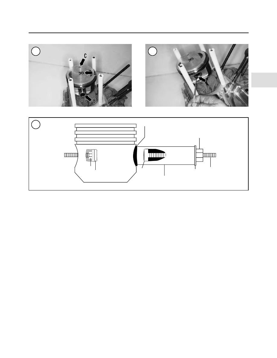
3. Lightly mark the pistons with F (front) or R (rear) (A,
Figure 139).

WARNING

The piston pin retaining rings may spring out
of the piston during removal. Wear safety
glasses when removing them in Step 4.

4. Using an awl, pry the piston pin circlips (Figure 140)
out of the piston. Place a thumb over the hole to help keep
the circlips from flying out during removal.

NOTE

Mark the piston pins so they can be rein-
stalled into their original pistons.

5. Support the piston and push out the piston pin (B, Fig-
ure 139
). If the piston pin is difficult to remove, use a pis-
ton pin removal tool (Figure 141).

6. Remove the piston from the connecting rod.

7. Remove the piston rings by using a ring expander tool
(Figure 142) or spreading them by hand (Figure 143).

8. Inspect the pistons, piston pins and pistons rings as de-
scribed in this chapter.

Piston Inspection

1. If necessary, remove the piston rings as described in
this chapter.

2. Carefully clean the carbon from the piston crown (Fig-
ure 144
) with a soft scraper. Large carbon accumulations

ENGINE

133

4

139

140

141

Pad

Nut

Nut

Threaded rod

Washer

Pipe

Piston pin

Piston pin

reduce piston cooling and cause detonation and piston
damage. Make sure the piston remains properly identified.

CAUTION

Be very careful not to gouge or otherwise
damage the piston when removing carbon.
Never use a wire brush to clean the piston
ring grooves. Do not attempt to remove car-
bon from the sides of the piston above the
top ring or from the cylinder bore near the
top. Removal of carbon from these two ar-
eas may cause increased oil consumption.

CAUTION

The pistons have a special coating on the
skirt (

Figure 145

). Do not scrape or use any

type of abrasive on this surface as it will be
damaged.

3. After cleaning the piston, examine the crown. The
crown should show no signs of wear or damage. If the
crown appears pecked or spongy-looking, check the spark
plug, valves and combustion chamber for aluminum de-
posits. If aluminum deposits are found, the engine is over-
heating.

4. Examine each ring groove for burrs, dented edges or
other damage. Pay particular attention to the top compres-
sion ring groove as it usually wears more than the others.
The oil rings and grooves generally wear less than com-
pression rings and their grooves. If the of oil ring groove is
worn or if the oil ring assembly is tight and difficult to re-
move, the piston skirt may have collapsed due to excessive
heat and is permanently deformed. Replace the piston.

5. Check the oil control holes (Figure 146) in the piston
for carbon or oil sludge buildup. Clean the holes with wire
and blow them out with compressed air.

6. Check the piston skirt (Figure 145) for cracks or other
damage. If a piston shows signs of partial seizure such as
aluminum build-up on the piston skirt, replace the piston

134

CHAPTER FOUR

144

145

146

143

142

to reduce the possibility of engine noise and further piston
seizure.

NOTE

If the piston skirt is worn or scuffed un-
evenly from side-to-side, the connecting rod
may be bent or twisted.

7. Check the retaining ring groove (Figure 147) on each
side for wear, cracks or other damage. If the grooves are
questionable, check the circlip fit by installing a new
circlip into each groove, then attempt to move the circlip
from side-to-side. If the circlip has any side play, the
groove is worn and the piston must be replaced.
8. Measure piston-to-cylinder clearance as described un-
der

Piston Clearance

in this chapter.

9. If the piston needs to be replaced, select a new piston
as described under

Piston Clearance

in this chapter. If the

piston, rings and cylinder are not damaged and are
dimensionally correct, they can be reused.

Piston Pin Inspection and Clearance

1. Clean the piston pin in solvent and dry it thoroughly.
2. Inspect the piston pin for chrome flaking or cracks. Re-
place if necessary.
3. Oil the piston pin and install it in the connecting rod
(Figure 148). Slowly rotate the piston pin and check for
radial play.
4. Oil the piston pin and install it in the piston (Figure
149
). Check the piston pin for excessive play.
5. To measure piston pin-to-piston clearance, perform the
following:

a. Measure the piston pin outer diameter with a mi-

crometer (Figure 150).

b. Measure the inside diameter of the piston pin bore

(Figure 151) with a telescoping gauge. Measure the
telescoping gauge with a micrometer.

ENGINE

135

4

147

148

149

150

151

c. Subtract the piston pin outer diameter from the pis-

ton pin bore to obtain the clearance dimension.
Check it against the specification in Table 2.

d. If it is out of specification, replace the piston and/or

the piston pin.

6. Replace the piston pin and/or piston or connecting rod
if necessary.

Piston Clearance

1. Make sure the piston skirt (Figure 145) and cylinder
bore (Figure 131) are clean and dry.
2. Measure the cylinder bore with a bore gauge (Figure
134
) as described under

Cylinder Inspection

in this chapter.

3. Measure the piston diameter with a micrometer as fol-
lows:

a. Hold the micrometer at the bottom of the piston

skirt at a right angle to the piston pin bore (Figure
152
). Adjust the micrometer so the spindle and an-
vil just touch the skirt.

b. Start below the bottom ring and slowly move the

micrometer toward the bottom of the skirt.

c. The micrometer will be loose, then tight at about 0.5

in. (12.7 mm) from the bottom, then loose again.

d. Measure the piston skirt at the tightest point.

4. Subtract the piston diameter from the largest bore di-
ameter; the difference is piston-to-cylinder clearance. If
the clearance exceeds the specification in Table 2, the pis-
tons should be replaced and the cylinders bored oversize
and then honed. Purchase the new pistons first. Measure
their diameter and add the specified clearance to deter-
mine the proper cylinder bore diameter.

Piston Pin Bushing in Connecting Rod
Inspection and Replacement

The piston pin bushings are reamed to provide correct

piston pin-to-bushing clearance. This clearance is critical
in preventing pin knock and top end damage.
1. Inspect the piston pin bushings (Figure 153) for exces-
sive wear or damage such as pit marks, scoring or wear
grooves. Then make sure the bushing is not loose. The
bushing must be a tight fit in the connecting rods.
2. Measure the piston pin diameter (Figure 150) where it
contacts the bushing.
3. Measure the piston pin bushing diameter using a snap
gauge (Figure 154).
4. Subtract the piston pin outer diameter from the bush-
ing inner diameter to determine piston pin-to-connecting
rod clearance. Replace the pin and bushing if the clear-
ance exceeds the service limit in Table 2.

Piston Pin Bushing Replacement

Special tools

The following special tools are required to replace and

ream the piston pin bushings. The clamp tool is only re-
quired if the bushing is being replaced with the crankcase
assembled. If these tools are not available, have a shop
with the proper equipment perform the procedure.
1. Connecting rod clamp tool (JIMS part No. 1284) or
(HD-95952-33B).
2. Connecting rod bushing tool (JIMS part No. 1051).

136

CHAPTER FOUR

152

153

154

3. Bushing reamer tool (JIMS part No. 1726-3).
4. Connecting rod bushing hone (part No. HD-422569).

Procedure

1. Remove two of the plastic hoses protecting the cylin-
der studs.
2. Install the connecting rod clamping tool as follows:

a. Install the clamp portion of the connecting rod

clamping tool over the connecting rod so the slots
engage the cylinder head studs. Do not scratch or
bend the studs.

b. Position the threaded cylinders with the knurled end

facing up and install the cylinders onto the studs.
Tighten the clamp securely.

c. Alternately tighten the thumbscrews on the side of

the connecting rod. Do not turn only one thumb-
screw, as this will move the connecting rod off cen-
ter and tightening the other thumbscrew will cause
the connecting rod to flex or bend.

3. Cover the crankcase opening to keep bushing particles
from falling into the engine.

NOTE

When installing the new bushing, align the
oil slot in the bushing with the oil hole in the
connecting rod.

4. Replace the bushing using the connecting rod bushing
tool (Figure 155) following the tool manufacturer’s in-
structions. The new bushing must be flush with both sides
of the connecting rod.
5. Ream the piston pin with the bushing reamer tool (Fig-
ure 156
) following the manufacturer’s instructions.
6. Hone the new bushing to obtain the piston pin clear-
ance in Table 2. Use honing oil, not engine oil, when hon-
ing the bushing to size.
7. Install the piston pin through the bushing. The pin
should move through the bushing smoothly. Confirm pin
clearance using a micrometer and bore gauge.
8. Carefully remove all metal debris from the crankcase.

Piston Ring Inspection

1. Clean the piston ring grooves as described under

Pis-

ton Inspection

.

2. Inspect the ring grooves for burrs, nicks, or broken or
cracked lands. Replace the piston if necessary.
3. Insert one piston ring into the top of its cylinder and
push it down approximately 1/2 in. (12.7 mm) using the
piston to square it in the bore. Measure the ring end gap
with a feeler gauge (Figure 157) and compare it with the

ENGINE

137

4

156

157

Feeler gauge

Piston ring

155

specification in Table 2. Replace the piston rings as a set
if any one ring end gap measurement is excessive. Repeat
Step 3 for each ring.

4. Roll each compression ring around its piston groove as
shown in Figure 158. The ring should move smoothly
with no binding. If a ring binds in its groove, check the
groove for damage. Replace the piston if necessary.

Piston Ring Installation

Each piston is equipped with three piston rings: two

compression rings (Figure 159) and one oil ring assembly
(Figure 160). The top compression ring is not marked.
The lower compression ring is marked with a dot.

Harley-Davidson recommends that

new

piston rings be

installed every time the piston is removed. Always lightly
hone the cylinder before installing new piston rings.

1. Wash the piston in hot, soapy water. Then rinse it with
cold water and dry it with compressed air. Make sure the
oil control holes in the lower ring groove are clear.

2. Install the oil ring assembly as follows:

a. The oil ring consists of three rings: a ribbed spacer

ring (A, Figure 160) and two steel rings (B).

b. Install the spacer ring into the lower ring groove.

Butt the spacer ring ends together. Do not overlap
the ring ends.

c. Insert one end of the first steel ring into the lower

groove so it is below the spacer ring. Then spiral the
other end over the piston crown and into the lower
groove. To prevent the ring end from scratching the
side of the piston, place a piece of shim stock or a
thin, flat feeler gauge between the ring and piston.

d. Repeat substep c to install the other steel ring above

the spacer ring.

NOTE

To install the compression rings, use a ring
expander as shown in

Figure 142

. Do not

expand the rings any more than necessary to
install them.

3. Install the lower compression ring with the dot facing
up (Figure 161).

4. Install the

new

top compression ring with either side

facing up.

5. Check the ring side clearance with a feeler gauge as
shown in Figure 162. Check the side clearance in several

138

CHAPTER FOUR

159

160

161

158

spots around the piston. If the clearance is larger than the
service limit in Table 2, replace the piston.
6. Stagger the ring gaps around the piston as shown in
Figure 138.

Piston Installation

1. Cover the crankcase openings to avoid dropping a
circlip into the engine.

2. Install a

new

piston pin circlip into one groove in the pis-

ton. Make sure the circlip seats in the groove completely.

3. Coat the connecting rod bushing and piston pin with
assembly oil.

4. Slide the piston pin into the piston until its end is flush
with the piston pin boss (Figure 163).

NOTE

The piston markings described in Step 5 are
for Harley-Davidson pistons. For aftermar-
ket pistons, follow their manufacturer’s di-
rections

for

piston

alignment

and

installation.

5. Place the piston over the connecting rod with its arrow
mark (C, Figure 139) facing toward the front of the engine.
Install used pistons on their original connecting rods; refer
to the marks made on the pistons during removal.

6. Push the piston pin (B, Figure 139) through the con-
necting rod bushing and into the other side of the piston.
Push the piston pin in until it bottoms on the circlip.

7. Install the other

new

piston pin circlip (Figure 164)

into the piston groove. Make sure it seats completely in
the piston groove (Figure 165).

8. Repeat Steps 1-7 for the other piston.

9. Install the cylinders as described in this chapter.

PUSHRODS

Removal/Installation

Remove and install the pushrods as described under

Rocker Arms And Pushrods

in this chapter.

ENGINE

139

4

163

164

165

162

Inspection

1. Disassemble the pushrod assembly (Figure 166) as
follows:

a. Remove the lower cover (Figure 167).

b. Remove the O-ring (Figure 168).

c. Remove the washer (Figure 169).

d. Remove the spring (Figure 170).

e. Remove the spring cap (Figure 171).

2. Check the upper cover assembly (Figure 172) as fol-
lows:

a. Check the spring for sagging or cracking.

b. Check the spacer for deformation or damage.

c. Check the pushrod covers for cracking or damage.

3. Check the pushrod ends (Figure 173) for wear.

4. Roll the pushrods on a surface plate or plate glass, and
check for bending.

5. Replace all worn or damaged parts. Install

new

O-rings.

140

CHAPTER FOUR

166

PUSHROD ASSEMBLY

1. O-ring
2. Upper cover
3. Spring cap retainer
4. Spring cap
5. Spring
6. Washer
7. Lower cover
8. Allen bolt
9. Lifter cover

10. Antirotation pin
11. Gasket
12. Hydraulic lifter
13. Pushrod

167

168

6. Reverse Step 1 to assemble the pushrod assembly.
Push the lower cover (A, Figure 174) into the spring cap
(B) to seat the O-ring.

VALVE LIFTERS

Figure 166 shows a valve lifter in relation to its pushrod

and valve lifter cover. The valve lifters and covers are in-
stalled on the right side of the engine. During engine oper-
ation, the lifters are pumped full of engine oil, thus taking
up all play in the valve train. When the engine is turned

off, the lifters leak down after a period of time as some of
the oil drains out. When the engine is started, the lifters
click until they completely refill with oil. The lifters are
working properly when they stop clicking after the engine
is run for a few minutes. If the clicking persists, there may
be a problem with the lifter(s).

Removal

During removal, store lifters in proper sequence so they

will be installed in their original position in the crankcase.

ENGINE

141

4

171

172

173

174

170

169

1. Remove the pushrods as described under

Rocker Arms

And Pushrods

in this chapter.

NOTE

In Step 2, loosen the two inner lifter cover
Allen bolts with a short 90

°

Allen wrench, as

shown in

Figure 175

, or a ball-end straight

Allen wrench.

2. Remove the lifter cover mounting bolts (Figure 176)
and remove the cover.
3. Remove the lifter cover gasket from the crankcase.

NOTE

Do not intermix the lifters in Step 4. Mark
them so they will be installed in their origi-
nal position.

4. Remove the anti-rotation pin (A, Figure 177) and both
hydraulic lifters (B).
5. Cover the crankcase opening with duct tape (Figure
178
) to prevent the entry of small parts.
6. If the lifters are not going to be inspected as described
in this section, store them upright in a container filled with
clean engine oil until installation.
7. Remove the lifter cover gasket.

Inspection

NOTE

Place the lifters on a clean, lint-free cloth
during inspection. Place inspected lifters in a
container of clean engine oil.

1. Check the pushrod socket (Figure 179) in the top of
the lifter for wear or damage.
2. Check the lifter roller (Figure 180) for pitting, scoring,
galling or excessive wear. If the rollers are worn exces-
sively, check the mating cam lobes for the same wear con-
dition.

142

CHAPTER FOUR

179

177

178

176

175

3. Clean the lifter rollers with contact cleaner. Then mea-
sure the roller fit and end clearance, and compare them to
the specification in Table 2. Replace the lifter assembly if
either part is worn to the service limit.
4. Determine the lifter-to-crankcase bore clearance as
follows:

a. Measure the lifter bore receptacle in the crankcase

and record the measurement.

b. Measure the lifter outside diameter (Figure 181)

and record the measurement.

c. Subtract substep b from substep a to determine the

lifter-to-crankcase bore clearance, then compare the
measurement to the service limit in Table 2. Re-
place the lifter or crankcase if the clearance is worn
to the service limit.

5. If a lifter does not show visual damage, it may be contam-
inated with dirt or have internal damage. If so, replace it. The
lifters are not serviceable and must be replaced as a unit.
6. After inspecting the lifters, store them in a container
filled with clean engine oil until installation.
7. If most of the oil has drained out of the lifter, refill it
with a pump-type oil can through the oil hole in the side of
the lifter.
8. Clean all gasket material from the mating surfaces of
the crankcase and the lifter cover.
9. Inspect the lifter cover (Figure 182) for cracks or dam-
age.

Installation

1. Remove the duct tape from the crankcase opening
(Figure 178).
2. Remove two of the lifters from the oil-filled container
and keep them vertical.
3. Install the lifters (Figure 183) into the crankcase re-
ceptacles with the flat surfaces facing toward the front and
rear of the engine.

CAUTION

Failure to install the anti-rotation pin will
allow the lifter to rotate off the camshaft
lobe, and cause severe internal engine dam-
age.

4. Install the anti-rotation pin (Figure 184). Make sure it
is seated correctly within the crankcase receptacle and
against the flats on both hydraulic lifters (B, Figure 177).
5. Rotate the engine until both lifters for the cylinder
head being serviced seat onto the cam’s lowest position
(base circle). The lifter’s top surface will be flush with the
top surface of the crankcase surface as shown in Figure
185
.

ENGINE

143

4

182

183

180

181

6. Install a

new

lifter cover gasket (Figure 186) onto the

crankcase.

NOTE

In Step 2, tighten the two inner lifter cover
Allen bolts with a short 90° Allen wrench as
shown in

Figure 175

, or ball-end straight

Allen wrench.

7. Install the lifter cover and the mounting bolts (Figure
176
). Tighten the bolts to the specification in Table 4.

8. Repeat Steps 1-7 to install the other set of lifters.

9. Install the pushrods as described under

Rocker Arms

And Pushrods

in this chapter.

OIL PUMP

The oil pump is mounted to the right side of the crank-

case under the camshaft support plate. The oil pump con-
sists of two sections: a feed pump (narrow rotors) which
supplies oil under pressure to the engine components and
a scavenger pump (wide rotors) which returns the oil from

144

CHAPTER FOUR

187

1. Feed pump (narrow)—

inner and outer rotors

2. Separator plate
3. Wave washer
4. Scavenger pump (wide)—

inner and outer rotors

5. O-ring
6. Housing
7. O-ring

188

OIL PUMP

184

185

186

the engine to the oil tank. The oil travels from the engine
to the oil tank through two interconnecting hoses.

Disassembly/Removal

The oil pump can be removed with the engine in the

frame. Refer to Figure 187.

1. Drain the engine oil as described in Chapter Three.

2. Remove the camshaft support plate assembly as de-
scribed under

Camshaft Support Plate Removal

in this

chapter.

3. Remove the feed pump inner and outer rotors (Figure
188
).

4. Remove the outer separator plate (Figure 189), wave
washer (Figure 190) and the inner separator plate (Figure
191
).

5. Remove the scavenger pump outer and inner rotors
(Figure 192).

6. Carefully pull the oil pump body (Figure 193) straight
off the crankshaft.

7. Remove the O-ring (Figure 194) from the backside of
the oil pump.

ENGINE

145

4

190

191

192

193

194

189

Inspection

1. Clean all parts thoroughly in solvent and place them on
a clean, lint-free cloth (Figure 195).

2. Inspect both sets of inner and outer rotors (Figure 196)
for scratches and abrasion.

3. Inspect the oil pump housing for scratches caused by
the rotors.

4. Inspect the interior passageways of the oil pump hous-
ing (Figure 197). Make sure all oil sludge and debris is re-
moved. Blow low-pressure compressed air through all oil
pump housing passages.

5. Install the inner rotor into the outer rotor. Check the
clearance between the inner tip and outer rotor (Figure
198
) with a flat feeler gauge. Replace the rotors as a set if
the clearance exceeds the dimension in Table 2. Also
measure the other set of rotors.

6. Measure the thickness of the inner (Figure 199) and
outer (Figure 200) rotors. Both rotors should be the same
thickness. If they are not, replace them as a complete set.
Also measure the other set of rotors.

146

CHAPTER FOUR

198

199

200

195

196

197

Assembly/Installation

NOTE

On oil pumps so equipped, position both in-
ner and outer rotor sets with the punch
marks (

Figure 201

, typical) facing out. If

the rotor set is not marked, position the ro-
tors in either orientation.

1. Install a

new

O-ring (Figure 194) onto the backside of

the oil pump. Apply clean engine oil to the O-ring.

2. Carefully push the oil pump body (Figure 193)
straight onto the crankshaft. Push it on until it bottoms.
Make sure the O-ring seats correctly in the crankcase fit-
ting (Figure 202).

3. Assemble the scavenge pump outer rotor onto the in-
ner rotor (Figure 203).

4. Align the flat on the scavenge inner rotor with the flat
on the crankshaft (Figure 204) and push the assembly
onto the crankshaft and into the oil pump housing (Figure
192
).

5. Align the tangs (A, Figure 205) on the inner separator
plate with the oil pump grooves (B) and install the inner
separator plate (Figure 191).

6. Install the wave washer (Figure 206).

ENGINE

147

4

203

204

205

206

201

202

7. Align the tangs on the outer separator (A, Figure 207)
plate with the oil pump grooves (B) and install the outer
separator plate (Figure 189).
8. Assemble the feed pump outer rotor onto the inner ro-
tor (Figure 208).
9. Align the flat on the feed pump inner rotor with the flat
on the crankshaft (Figure 188) and install the assembly
onto the crankshaft and into the oil pump housing.
10. Install the camshaft support plate assembly as de-
scribed under

Camshaft Support Plate Installation

in this

chapter.
11. Refill the engine oil as described in Chapter Three.

OIL TANK AND OIL LINES

The Hose Clamp Pliers (part No. HD 97087-65B) and

The Oil Line Remover and Replacement tool (part No.
HD-4445) are required to remove and install the oil lines
at the oil tank and engine.

There are two sizes of oil line retainers and fittings. Use

the correct size tool for all service procedures.

New

hose clamps must be used during installation.

Removal/Installation

Refer to Figure 209.

1. Remove the seat as described in Chapter Fourteen.
2. Remove the exhaust system as described in Chapter
Seven.
3. Remove the battery as described in Chapter Eight.
4. Drain the engine oil as described under

Engine Oil and

Filter Change

in Chapter Three.

5. Remove the rear inner fender as described under

Rear

Fender Inner Panel Removal/Installation

in Chapter

Fourteen.
6. Remove the two bolts (Figure 210) securing the elec-
trical panel to the back of the oil tank.
7. Disconnect the oil tank return line and vent line from
the oil tank and engine as follows:

NOTE

Do not remove the retainer and O-rings
from the fitting on the oil tank and crank-
case. If the fitting(s) is leaking oil, then the
retainer must be removed and repaired.

a. At the oil tank, pull the chrome cover (A, Figure

211) off the oil line.

b. Wrap the special tool around the oil line and insert

the tool into the retainer (B, Figure 211) on the oil
tank fitting.

c. Carefully pull the oil line straight out of the fitting.

The retainer must stay within the oil tank fitting.

d. Repeat substeps b and c for the fittings on the crank-

case (Figure 212).

8. Remove the two bolts (A, Figure 213) behind the fuse
block. Lift the fuse block (B) and set it aside.

9. Remove the two bolts and washers (A, Figure 214) se-
curing the top bracket.

10. Remove the two screws, washers and flange nuts and
remove the battery storage tray (B, Figure 214).

11. Remove the clamp securing the drain hose to the
frame cross member (Figure 215).

12. Remove both clamps securing the oil feed hose (Fig-
ure 216
) and remove the hose from the oil tank.

13. Note the routing of the battery positive cable (C, Fig-
ure 214
) routing behind the oil tank and the frame. It must
be installed in the same location during oil tank installa-
tion.

14. Carefully remove the oil tank out from the right side
of the frame.

15. Install the oil tank by reversing these removal steps.
Note the following:

a. Install

new

clamps on the oil feed hose (Figure

216).

148

CHAPTER FOUR

207

208


Content      ..     12      13      14      15     ..