Harley Davidson Softail 2000-2005. Service manual - page 13
 

  Главная      Harley Davidson     Harley Davidson Softail 2000-2005. Service manual


Search            copyright infringement  


Content      ..     11      12      13      14     ..


Harley Davidson Softail 2000-2005. Service manual - page 13


12. Check the valves and valve guides as described under

Valves and Valve Components

in this chapter.

Installation

1. If removed, install the piston and cylinder as described
in this chapter.

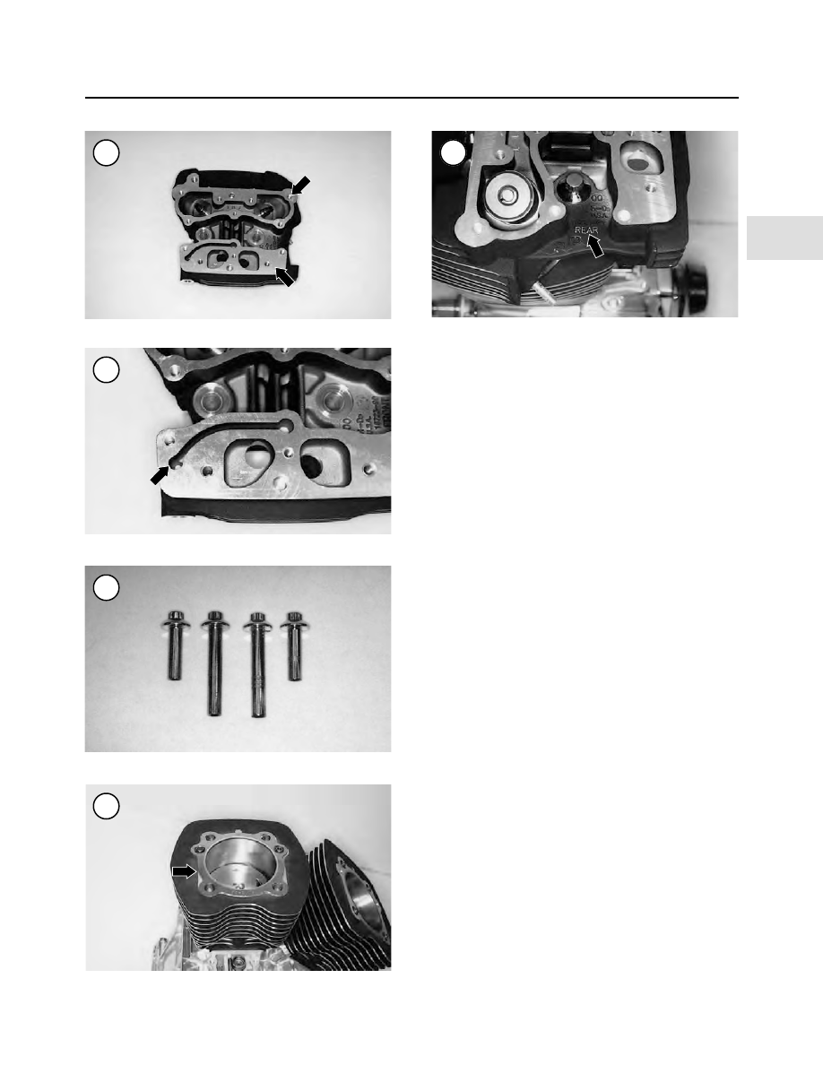
2. Lubricate the cylinder studs and cylinder head bolts as
follows:

a. Clean the cylinder head bolts in solvent and dry

with compressed air.

b. Apply clean engine oil to the cylinder head bolt

threads and to the flat shoulder surface on each bolt
(Figure 88). Wipe excess oil from the bolts, leave
only an oil film on these surfaces.

3. Install the two dowel pins (Figure 78) into the top of
the cylinder.

4. Install a

new

O-ring over each dowel pin. Apply a light

coat of clean engine oil to the O-rings.

CAUTION

Because the O-rings center the head gasket
on the cylinder, install them before install-
ing the head gasket.

5. Install a

new

cylinder head gasket (Figure 89) onto the

cylinder.

CAUTION

Do not use sealer on the cylinder head gas-
ket. For an aftermarket head gasket, follow
the manufacturer’s instructions for gasket
installation.

NOTE

The cylinder heads are

not

identical. Refer

to the FRONT or REAR mark (

Figure 90

)

cast into top surface of the cylinder head.

ENGINE

117

4

86

87

88

89

90

6. Install the cylinder head (Figure 91) onto the cylinder
and the dowel pins. Position the head carefully to avoid
moving the head gasket out of alignment.
7. Install and finger-tighten the cylinder head bolts. Make
sure the short bolts are on the spark plug side.

CAUTION

Failure to follow the torque pattern and se-
quence in Step 8 may cause cylinder head
distortion and gasket leakage.

8. Refer to Figure 92 for the front and rear cylinder head
bolt tightening sequence. Torque the cylinder head bolts
as follows:

a. Starting with bolt No. 1, tighten each bolt in order to

84-97 in.-lb. (9-11 N•m).

b. Starting with bolt No. 1, tighten each bolt in order to

177-203 in.-lb. (20-23 N•m).

c. Make a vertical mark with a permanent marker on

each bolt head (A, Figure 93). Make another mark
on the cylinder head (B, Figure 93) at a 90

°

angle,

or 1/4 turn from the mark on the bolt head.

d. Use the marks as a guide and tighten each bolt head

90°, or 1/4 turn, clockwise until the marks are
aligned (Figure 94).

9. Install the rocker arm assemblies and pushrods as de-
scribed in this chapter.

VALVES AND VALVE COMPONENTS

Complete valve service requires a number of special

tools, including a valve spring compressor to remove and
install the valves. The following procedures describe how
to check for valve component wear and determine what
type of service is required.

Valve Removal

1. Remove the cylinder head as described in this chapter.
2. Install the valve spring compressor (Figure 95)
squarely over the valve spring upper retainer (Figure 96)
and against the valve head.

CAUTION

To avoid loss of spring tension, compress
the spring only enough to remove the valve
keepers.

3. Tighten the valve spring compressor until the valve
keepers separate from the valve stem. Lift the valve keep-
ers out through the valve spring compressor with a magnet
or needlenose pliers.

118

CHAPTER FOUR

91

92

93

Front cylinder head

Rear cylinder head

94

4. Gradually loosen the valve spring compressor and re-
move it from the cylinder head.
5. Remove the spring retainer and the valve springs.

CAUTION

Remove any burrs from the valve stem
groove before removing the valve (

Figure

97

); otherwise the valve guide will be dam-

aged as the valve stem passes through it.

6. Remove the valve from the cylinder while rotating it
slightly.
7. Remove the valve spring lower retainer.
8. Remove the valve guide oil seal.

CAUTION

Keep the components of each valve assem-
bly together by placing each set in a divided
carton, or into separate small boxes or
small reclosable plastic bags. Identify the
components as either intake or exhaust. If
both cylinders are disassembled, also label
the components as front and rear. Do not in-
termix components from the valves or exces-
sive wear may result.

9. Repeat Steps 3-8 to remove the remaining valve.

Valve Inspection

When measuring the valves and valve components in

this section, compare the actual measurements to the new
and wear limit specifications in Table 2. Replace parts
that are out of specification or are damaged as described in
this section.
1. Clean valves in solvent. Do not gouge or damage the
valve seating surface.
2. Inspect the valve face. Minor roughness and pitting
(Figure 98) can be removed by lapping the valve as de-
scribed in this chapter. Excessive unevenness to the con-
tact surface indicates the valve is not serviceable.
3. Inspect the valve stem for wear and roughness. Then
measure the valve stem outside diameter with a microme-
ter (Figure 99).
4. Remove all carbon and varnish from the valve guides
with a stiff spiral wire brush before measuring wear.
5. Measure the valve guide inside diameter with a small
hole gauge (Figure 100). Measure at the top, center and
bottom positions. Then measure the small hole gauge.
6. Determine the valve stem-to-valve guide clearance by
subtracting the valve stem outside diameter from the
valve guide inner diameter.
7. If a small hole gauge is not available, insert each valve
into its guide. Attach a dial indicator to the valve stem

ENGINE

119

4

95

96

97

98

Deburr

Valve stem

next to the head (Figure 101). Hold the valve slightly off
its seat and rock it sideways in both directions 90° to each
other. If the valve rocks more than slightly, the guide is
probably

worn.

Take

the

cylinder

head

to

a

Harley-Davidson dealership or machine shop and have
the valve guides measured.

8. Check the inner and outer valve springs as follows:

a. Inspect each of the valve springs (Figure 102) for

visual damage.

b. Use a square to visually check the spring for distor-

tion or tilt (Figure 103).

c. Measure the valve spring free length with a vernier

caliper (Figure 104) and compare it to the specifi-
cation.

d. Repeat substeps a-c for each valve spring.

e. Replace defective springs as a set (inner and outer).

9. Check the valve spring upper and lower retainers seats
for cracks or other damage.

10. Check the valve keepers fit on the valve stem end
(Figure 105). They should index tightly into the valve
stem groove.

11. Inspect the valve seats (Figure 106) in the cylinder
head. If they are worn or burned, they can be recondi-
tioned as described in this chapter. Seats and valves in
near-perfect condition can be reconditioned by lapping
with fine Carborundum paste.

a. Clean the valve seat and corresponding valve mat-

ing areas with contact cleaner.

b. Coat the valve seat with layout fluid.

c. Install the valve into its guide and tap it against its

seat. Do not rotate the valve.

d. Lift the valve out of the guide and measure the seat

width at various points around the seat with a ver-
nier caliper.

e. Compare the seat width with the specification. If the

seat width is less than specified or uneven, resurface
the seats as described in this chapter.

120

CHAPTER FOUR

99

100

101

102

103

Dial indicator

Y

X

f. Remove all layout fluid residue from the seats and

valves.

Valve Installation

1. Clean the end of the valve guide.

2. Install the spring lower retainer (Figure 107). Push
down until it is seated on the cylinder head surface (Fig-
ure 108
).

3. Coat a valve stem with Torco MPZ, molybdenum
disulfide paste or equivalent. Install the valve partway
into the guide. Then slowly turn the valve as it enters the
oil seal and continue turning it until the valve is installed
all the way.

4. Work the valve back and forth in the valve guide to en-
sure the lubricant is distributed evenly within.

5. Withdraw the valve and apply an additional coat of the
lubricant.

6. Reinstall the valve into the valve guide but do not push
the valve past the top of the valve guide.

7. Use isopropyl alcohol and thoroughly clean all lubri-
cant from the outer surface of the valve guide.

CAUTION

Do not allow any of the retaining compound
to enter the valve guide bore.

8. Apply Loctite Retaining Compound RC/620 or an
equivalent to the oil seal seating surface and to the outer
surface of the valve guide.

9. Push the valve all the way into the cylinder head until it
bottoms (A, Figure 109).

CAUTION

The oil seal will be torn as it passes the
valve stem keeper groove if the plastic cap-
sule is not installed in Step 10. The capsule
is included in the top end gasket set.

ENGINE

121

4

104

105

106

107

108

10. Hold the valve in place and install the plastic capsule
(B, Figure 109) onto the end of the valve stem. Apply a
light coat of clean engine oil to the outer surface of the
capsule.
11. With the valve held in place, install the oil seal (Fig-
ure 110
) onto the valve stem.
12A. If special tools are used, use the Harley-Davidson
valve seal installation tool (part No. HD-34643A) and
driver handle (part No. HD-34740) (Figure 111) to push
the oil seal down until it bottoms on the cylinder head sur-
face.
12B. If special tools are not used, use an appropriate-size
deep socket (Figure 112) to push the oil seal down until it
bottoms on the cylinder head surface.
13. Remove the plastic capsule from the valve stem.
Keep the capsule as it will be used on the remaining
valves.
14. Install the inner valve spring (Figure 113) and make
sure it is properly seated on the lower spring retainer.
15. Install the outer valve spring (Figure 114) and make
sure it is properly seated on the lower spring retainer.
16. Install the upper spring retainer (Figure 115) on top
of the valve springs.

CAUTION

To avoid loss of spring tension, only com-
press the springs enough to install the valve
keepers.

17. Compress the valve springs with a valve spring com-
pressor (Figure 95) and install the valve keepers (Figure
116
).
18. Make sure both keepers are seated around the valve
stem prior to releasing the compressor.
19. Slowly release tension from the compressor and re-
move it. After removing the compressor, inspect the valve
keepers to make sure they are properly seated (Figure
117
). Tap the end of the valve stem with a

soft-faced

ham-

mer to ensure the keepers are properly seated.

122

CHAPTER FOUR

109

110

111

VALVE SEAL

INSTALLATION

1. Driver handle
2. Valve seal installation tool
3. Oil seal
4. Valve guide
5. Lower spring seat

20. Repeat Steps 1-19 for the remaining valves.
21. Install the cylinder head as described in this chapter.

Valve Guide Replacement

Special tools

The following tools or their equivalents are required to

replace the valve guides:
1. Driver handle and remover (HD 34740).
2. Valve guide installation sleeve (HD-34741).
3. Valve guide reamer (HD-39932) and T-handle (HD
39847).
4. Valve guide reamer (HD-39964) and honing lubricant.
5. Valve guide hone (HD-34723).
6. Valve guide brush (HD-34751).

Procedure

1. Place the cylinder head on a wooden surface with the
combustion chamber side facing down.
2. Shoulderless valve guides (Figure 118) are used. Be-
fore the valve guides are removed, note and record the
shape of the guide that projects into the combustion cham-
ber. If the valve guide installation tool is

not

going to be

ENGINE

123

4

112

113

114

115

116

117

used, measure the distance from the face of the guide to
the cylinder head surface with a vernier caliper (Figure
119
). Record the distance for each valve guide. The new
valve guides must be installed to this

exact

height dimen-

sion.

3. Remove the valve guides as follows:

CAUTION

Use the correct size valve guide removal
tool to remove the valve guides or the tool
may expand the end of the guide. An ex-
panded guide will widen and damage the
guide bore in the cylinder head as it passes
through it.

NOTE

The valve guides can either be pressed out
or driven out. Pressing the guides out is rec-
ommended since it lessens the chance of cyl-
inder head damage.

a. Support the cylinder head so the combustion cham-

ber faces down.

b. To drive the guides out, place the cylinder on a piece

of wood.

c. To press the guides out, support the cylinder head in

the press with a cylinder head stand (JIMS part No.
39782) so the valve guide is perpendicular to the
press table.

d. Insert the driver handle and remover into the top of

the valve guide.

e. Press or drive the valve guide out through the com-

bustion chamber.

f. Repeat substeps a-e for the remaining valve guides.

4. Clean the valve guide bores in the cylinder head.

5. Because the valve guide bores in the cylinder head
may have enlarged during removal of the old guides, mea-
sure each valve guide bore prior to purchasing the new
guides. Then purchase the new valve guides to match their
respective bore diameters. Determine the bore diameter as
follows:

a. Measure the valve guide bore diameter in the cylin-

der head with a bore gauge or snap gauge. Record
the bore diameter.

b. The new valve guide outside diameter must be

0.0020-0.0033 in. (0.050-0.083 mm) larger than the
guide bore in the cylinder head. When purchasing
new valve guides, measure the new guide’s outside
diameter with a micrometer. If the new guide’s out-
side diameter is not within this specification, install
oversize valve guide(s). See a Harley-Davidson
dealership for available sizes and part numbers.

6. Apply a thin coat of molylube or white grease to the
entire outer surface of the valve guide before installing it
in the cylinder head.

CAUTION

When installing oversize valve guides, make
sure to match each guide to its respective
bore in the cylinder head.

7. Install the new guide using the driver handle and valve
guide installation tools. Press or drive the guide into the
cylinder head until the valve guide installation tool bot-
toms out on the cylinder head surface. When the tool bot-
toms on the cylinder head surface, the valve guide is
installed to the correct height. If the driver handle tool is
not used, install the valve guide to the same height re-
corded prior to removal. Measure the valve guide’s in-
stalled height using a vernier caliper (Figure 119) during
installation.

NOTE

Replacement valve guides are sold with a
smaller inside diameter than the valve stem.
Ream the guide to fit the valve stem.

8. Ream the new valve guide as follows:

124

CHAPTER FOUR

118

119

a. Apply a liberal amount of reamer lubricant to the

ream bit and to the valve guide bore.

b. Start the reamer straight into the valve guide bore.

CAUTION

Only apply pressure to the end of the drive
socket. If pressure is applied to the T-han-
dle, the bore will be uneven, rough cut and
tapered.

c. Apply thumb pressure to the end of the drive socket

portion of the T-handle while rotating the T-handle

clockwise

. Only

light

pressure is required. Apply

additional lubricant to the reamer and into the valve
guide while rotating the reamer.

d. Continue to rotate the reamer until the entire bit has

traveled through the valve guide and the shank of
the reamer rotates freely.

CAUTION

Never back the reamer out through the valve
guide as the guide will be damaged.

e. Remove the T-handle from the reamer. Remove the

reamer from the combustion chamber side of the
cylinder head.

f. Apply low-pressure compressed air to remove the

small shavings from the valve guide bore. Then
clean the valve guide bore with the small spiral
brush.

9. Hone the valve guide as follows:

a. Install the valve guide hone into a high-speed elec-

tric drill.

b. Lubricate the valve guide bore and hone stones with

the reamer lubricant—

do not use motor oil

.

c. Carefully insert the hone stones into the valve guide

bore.

d. Start the drill and move the hone back and forth in

the valve guide bore for 10 to 12 complete strokes to
obtain a 60° crosshatch pattern.

10. Repeat Steps 8 and 9 for each valve guide.
11. Soak the cylinder head in a container filled with hot,
soapy water. Then clean the valve guides with a valve
guide brush or an equivalent bristle brush.

Do not use a

steel brush

. Do not use cleaning solvent, kerosene or gas-

oline as these chemicals will not remove all of the abra-
sive particles produced during the honing operation.
Repeat this step until all of the valve guides are thor-
oughly cleaned. Then rinse the cylinder head and valve
guides in clear, cold water and dry them with compressed
air.
12. After cleaning and drying the valve guides, apply
clean engine oil to the guides to prevent rust.
13. Resurface the valve seats as described in

Valve Seat

Reconditioning

in this section.

Valve Seat Inspection

1. Remove all carbon residue from each valve seat. Then
clean the cylinder head as described under

Valve Inspec-

tion

in this section.

NOTE

Machinist’s dye is the most accurate method
of checking the valve seat width and posi-
tion.

2. Check the valve seats in their original locations with
machinist’s dye as follows:

a. Thoroughly clean the valve face and valve seat with

contact cleaner.

b. Spread a thin layer of Prussian blue or machinist’s

dye evenly on the valve face.

c. Insert the valve into its guide.
d. Support the valve by hand and tap the valve up and

down in the cylinder head (Figure 120). Do not ro-
tate the valve or the reading will be false.

e. Remove the valve and examine the impression left

by the machinist’s dye. The impressions on the
valve and the seat should be even around their cir-
cumferences and the width (Figure 121) should be
within the specifications in Table 2. If the width is
beyond the specification or if the impression is un-
even, recondition the valve seats.

3. Closely examine the valve seat in the cylinder head
(Figure 106). It should be smooth and even with a pol-
ished seating surface.

ENGINE

125

4

120

4. If the valve seat is in good condition, install the valve
as described in this chapter.
5. If the valve seat is not correct, recondition the valve
seat as described in this chapter.

Valve Seat Reconditioning

Valve seat reconditioning requires considerable exper-

tise and special tools. In most cases, it is more economical
and practical to have these procedures performed by an
experienced machinist.

The following procedure is provided for those equipped

to perform the task. A valve seat cutter set (HD-35758A)
or equivalent is required. Follow the manufacturer’s in-
structions.

Refer to Figure 122 for valve seat angles. While the

valve seat angles for both the intake and exhaust valves
are the same, different cutter sizes are required. Also note
that a 45° seat angle is specified to grind the seats, while a
46° seat angle is specified to cut the seats

.

1. Clean the valve guides as described under

Valve In-

spection

in this section.

2. Carefully rotate and insert the solid pilot into the valve
guide. Make sure the pilot is correctly seated.

CAUTION

Valve seat accuracy depends on a correctly
sized and installed pilot.

3. Using the 45° grinding stone or 46° cutter, descale and
clean the valve seat with one or two turns.

CAUTION

Measure the valve seat width in the cylinder
head (

Figure 121

) after each cut to make

sure

its

size

and

area

are

correct.

Over-grinding will lower the valves into the
cylinder head and of the valve seat will have
to be replaced.

4. If the seat is still pitted or burned, turn the cutter until
the surface is clean. Work slowly and carefully to avoid
removing too much material from the valve seat.
5. Remove the pilot from the valve guide.
6. Apply a small amount of valve lapping compound to
the valve face and install the valve. Rotate the valve
against the valve seat using a valve lapping tool. Remove
the valve.
7. Measure the valve seat width with a vernier caliper
(Figure 121 and Figure 122). Record the measurement to
use as a reference point when performing the following
steps.

CAUTION

The 31° cutter removes material quickly.
Work carefully and check the progress often.

8. Reinsert the solid pilot into the valve guide. Make sure
the pilot is properly seated. Install the 31 ° cutter onto the
solid pilot and lightly cut the seat to remove 1/4 of the ex-
isting valve seat.
9. Install the 60° cutter onto the solid pilot and lightly cut
the seat to remove the lower 1/4 of the existing valve seat.
10. Measure the valve seat with a vernier caliper. Then fit
the 45° grinding stone or 46° cutter onto the solid pilot and
cut the valve seat to the specified seat width in Table 2.
11. When the valve seat width is correct, check valve
seating as follows:
12. Remove the solid pilot from the cylinder head.
13. Inspect the valve seat-to-valve face impression as fol-
lows:

a. Clean the valve seat with contact cleaner.
b. Spread a thin layer of Prussian Blue or machinist’s

dye evenly on the valve face.

c. Insert the valve into its guide.
d. Support the valve with two fingers and turn it with

the valve lapping tool.

e. Remove the valve and examine the impression left

by the Prussian blue or machinist’s dye.

126

CHAPTER FOUR

121

Valve seat width

f. Measure the valve seat width (Figure 121 and Fig-

ure 122). Refer to Table 2 for the correct seat width.

g. The valve seat contact area must be in the center of

the valve face area.

14. If the contact area is too high or too wide on the valve,
cut the seat with the 31° cutter. This will remove part of
the top valve seat area to lower or narrow the contact area.
15. If the contact area is too low or too wide on the valve,
use the 60° cutter and remove part of the lower area to
raise and widen the contact area.
16. After obtaining the desired valve seat position and
angle, use the 45° grinding stone or the 46° cutter and

lightly

clean off any burrs caused by the previous cuts.

17. When the contact area is correct, lap the valve as de-
scribed in this chapter.
18. Repeat Steps 1-17 for the remaining valve seats.
19. Thoroughly clean the cylinder head and all valve
components in solvent, then clean them with detergent
and hot water, and rinse in cold water. Dry them with com-
pressed air. Then apply a light coat of engine oil to all
non-aluminum surfaces to prevent rust formation.
20. After reconditioning the valve seats, check the valve
stem protrusion into the cylinder head as follows:

a. Install the valve into the cylinder head and place a

finger on the valve head to keep it seated against the
valve seat.

b. Use a vernier caliper and measure the distance from

the top of the valve stem to the machined surface of
the cylinder head (Figure 121).

c. If the protrusion exceeds 2.064 in. (52.43 mm) ei-

ther the valve seat or valve stem or both are worn.
Replace the worn part(s).

CAUTION

Do not grind the end of the valve stem as the
hardness of the valve stem will be removed,
resulting in premature valve stem wear.

Valve Lapping

If valve wear or distortion is not excessive, attempt to

restore the valve seal by lapping the valve to the seat.

After lapping the valves, install the valve assemblies

and test each valve seat for a good seal by pouring solvent
into the ports (Figure 123). If the seal is good, no solvent
will leak past the seat surface. If solvent leaks past any
seat, the combustion chamber will appear wet. Disassem-
ble the leaking valve and repeat the lapping procedure or
recondition the valve as described in this chapter.
1. Smear a light coat of fine grade valve lapping com-
pound on the seating surface of the valve.
2. Insert the valve into the head.

ENGINE

127

4

123

122

Cylinder head

Seat

60

!

Margin

46

!

cutting

45

!

grinding

Valve

31

!

0.040-0.062 in.
(1.02-1.58 mm)

Port

Solvent

or

kerosene

Valve

Combustion
chamber

3. Wet the suction cup of the lapping tool and stick it onto
the head of the valve. Lap the valve to the seat by spinning
the tool between both hands while lifting and moving the
valve around the seat 1/4 turn at a time.

4. Wipe off the valve and seat frequently to check the
progress. Lap only enough to achieve a precise seating
ring around the valve head.

5. Closely examine the valve seat in the cylinder head.
The seat must be smooth and even with a polished seating
ring.

6. Thoroughly clean the valves and cylinder head in sol-
vent to remove all grinding compound residue. Com-
pound left on the valves or the cylinder head will cause
rapid engine wear.

7. After installing the valves into the cylinder head, test
each valve for proper seating. Pour solvent into the intake
and exhaust ports. Solvent should not leak past the valve
seats. If the solvent leaks, the combustion chamber will
appear wet. If solvent leaks past any of the seats, disas-
semble that valve assembly and repeat the lapping proce-
dure until there is no leakage.

Valve Seat Replacement

Valve seat replacement requires considerable experi-

ence

and

equipment.

Refer

this

work

to

a

Harley-Davidson dealership or machine shop.

CYLINDER

Refer to Figure 124.

Removal

1. Remove the cylinder head as described in this chapter.
2. Remove all dirt and debris from the cylinder base.
3. Remove the two dowel pins and O-rings (Figure 125)
from the top of the cylinder if they are still in place.
4. Turn the crankshaft until the piston is at bottom dead
center (BDC).

NOTE

The front and rear cylinders are identical
(same part number). Mark each cylinder so

128

CHAPTER FOUR

124

PISTON/CYLINDER ASSEMBLY

1. Upper compression ring
2. Lower compression ring
3. Upper oil ring
4. Spacer
5. Lower oil ring
6. Circlip
7. Piston
8. Connecting rod bushing
9. Connecting rod

10. Piston pin
11. O-ring
12. Locating dowel
13. Cylinder
14. O-ring seal

they will be reinstalled in their original po-
sitions.

5. Pull the cylinder straight up and off the piston and cyl-
inder studs. If necessary, tap around the perimeter of the
cylinder with a rubber or plastic mallet.

6. Place clean shop rags (A, Figure 126) into the crank-
case opening to prevent objects from falling undetected
into the crankcase.

7. Remove the O-ring seal (B, Figure 126) from the lo-
cating dowel. Leave the locating dowels in place unless
they are loose.

8. Remove the O-ring (Figure 127) from the base of the
cylinder.

9. Install a vinyl or rubber hose over each stud (Figure
128
). This will protect both the piston and the studs from
damage.

CAUTION

After removing the cylinder, be careful when
working around the cylinder studs to avoid
bending or damaging them. The slightest
bend could cause the stud to fail.

10. Repeat these steps to remove the other cylinder.

Inspection

To obtain an accurate cylinder bore measurement, the

cylinder must be torqued between torque plates (JIMS
part No. 1287). Measurements made without the torque
plates will be inaccurate and may vary by as much as
0.001 in. (0.025 mm). Refer this procedure to a shop
equipped and experienced with this procedure if the tools
are not available. The cylinder bore must be thoroughly
clean and at room temperature to obtain accurate mea-
surements. Do not measure the cylinder immediately after
it has been honed as it will still be warm. Measurements
can vary by as much as 0.002 in. (0.051 mm) if the cylin-
der block is not at room temperature.

1. Thoroughly clean the outside of the cylinder. Use a
stiff brush, soap and water to clean all debris from the
cooling fins (Figure 129). If necessary, use a piece of
wood to scrape away lodged dirt. Clogged cooling fins
can cause overheating and lead to possible engine dam-
age.

2. Carefully remove all gasket residue from the top and
bottom cylinder block gasket surfaces.

3. Thoroughly clean the cylinder with solvent and dry it
with compressed air. Lightly oil the cylinder block bore to
prevent rust.

ENGINE

129

4

126

127

128

125

4. Check the top and bottom cylinder gasket surfaces
with a straightedge and feeler gauge (Figure 130). Re-
place the cylinder if warp exceeds the limit in Table 2.
5. Check the cylinder bore (Figure 131) for scuff marks,
scratches or other damage.
6. Install the torque plate onto the cylinder (Figure 132)
following the manufacturer’s instructions.
7. Measure the cylinder bore with a bore gauge or inside
micrometer at the positions indicated in Figure 133. Per-
form the first measurement 0.500 in. (12.7 mm) below the
top of the cylinder (Figure 134). Do not measure areas
where the rings do not travel.
8. Measure in two axes aligned with the piston pin and at
90 ° to the pin. If the taper or out-of-round measurements
exceed the service limits in Table 2, bore both cylinders to
the next oversize and install oversize pistons and rings.
Confirm the accuracy of all measurements and consult
with a parts supplier on the availability of replacement
parts before having the cylinder serviced.
9. Remove the torque plates.
10. If the cylinders were serviced, wash each cylinder in
hot, soapy water to remove the fine grit material left from
the boring or honing process. Run a clean white cloth
through the cylinder bore. If the cloth shows traces of grit
or oil, the bore is not clean. Wash the cylinder until the

cloth passes through cleanly. When the bore is clean, dry it
with compressed air, then lubricate it with clean engine oil
to prevent the bore from rusting.

CAUTION

Only hot, soapy water will completely clean
the cylinder bore. Solvent and kerosene can-
not wash fine grit out of the cylinder crev-
ices. Abrasive grit left in the cylinder will
cause premature engine wear.

Studs and bolts

The cylinder studs and cylinder head bolts must be in

good condition and properly cleaned before the cylinder
and cylinder heads are installed. Damaged or dirty studs
may cause cylinder head distortion and gasket leaks.

CAUTION

The cylinder studs, cylinder head bolts and
washers consist of hardened material. Do not
substitute them with parts made of a lower
grade material. If replacement is required,
purchase the parts from the manufacturer.

130

CHAPTER FOUR

131

132

130

129

1. Inspect the cylinder head bolts. Replace any that are
damaged.

2. Examine the cylinder studs for bending, looseness or
damage. Replace studs as described under

Cylinder Stud

Replacement

in this chapter. If the studs are in good condi-

tion, perform Step 3.

3. Cover both crankcase openings with shop rags to pre-
vent debris from falling into the engine.

4. Remove all carbon residue from the cylinder studs and
cylinder head bolts as follows:

a. Apply solvent to the cylinder stud and mating cylin-

der head bolt threads, and thread the bolt onto the
stud.

b. Turn the cylinder head bolt back and forth to loosen

and remove the carbon residue from the threads.
Remove the bolt from the stud. Wipe off the residue
with a shop rag moistened in cleaning solvent.

c. Repeat substeps a and b until both thread sets are

free of carbon residue.

d. Spray the cylinder stud and cylinder head bolt with

an aerosol parts cleaner and allow them to dry.

e. Set the clean bolt aside and install it on the same

stud when installing the cylinder head.

5. Repeat Step 4 for each cylinder stud and cylinder head
bolt set.

Installation

NOTE

If a cylinder has been bored oversize, the in-
ner lead-in angle at the base of the bore skirt
(

Figure 135

) has been eliminated. This

lead-in angle is necessary for the piston
rings to safely enter the cylinder bore. If
necessary, use a chamfering cone (JIMS

ENGINE

131

4

133

Bolt

Torque plate

Cylinder

Nut

Bottom

Torque plate

Middle

Top

134

part No. 2078) or a hand grinder with a fine
stone to make a new lead-in angle. The fin-
ished surface must be smooth so it will not
catch and damage the piston rings during
installation.

1. If removed, install the pistons and rings as described in
this chapter.
2. Remove gasket residue and clean the cylinder as de-
scribed under

Inspection

in this chapter.

3. Remove the vinyl or rubber hose from each stud (A,
Figure 136).
4. Install a

new

O-ring onto the base of the cylinder. Ap-

ply a light coat of clean engine oil to the O-ring.
5. If removed, install the locating dowels (Figure 137)
onto the crankcase.
6. Install a

new

O-ring seal (B, Figure 126) onto the lo-

cating dowel. Apply a light coat of clean engine oil to the
O-ring.
7. Turn the crankshaft until the piston is at top dead center
(TDC).
8. Lubricate the cylinder bore, piston and piston rings lib-
erally with clean engine oil.
9. Position the top compression ring gap so it is facing the
intake port. Then stagger the remaining piston ring end
gaps as shown in Figure 138.

10. Compress the piston rings with a ring compressor (B,
Figure 136).

NOTE

Install the cylinder in its original position as
noted during removal.

11. Carefully align the cylinder (front facing forward)
with the cylinder studs and slide it down until it is over the
top of the piston. Continue sliding the cylinder down past
the rings. Remove the ring compressor once the piston

132

CHAPTER FOUR

136

137

138

135


Content      ..     11      12      13      14     ..