Harley Davidson Softail 2000-2005. Service manual - page 12
 

  Главная      Harley Davidson     Harley Davidson Softail 2000-2005. Service manual


Search            copyright infringement  


Content      ..     10      11      12      13     ..


Harley Davidson Softail 2000-2005. Service manual - page 12


24. On 2000 models, install the camshaft position sensor
as described in Chapter Eight.

25. Install the drive belt guard and tighten the bolts se-
curely.

26. Install the oil tank as described in this chapter.

27. Connect the speed sensor connector (Figure 5) and
attach the electrical harness to the transmission case.

28. Install the rear fender inner panel (to cover the electri-
cal panel) as described in Chapter Eight.
29. Adjust the clutch and primary chain as described in
Chapter Three.
30. On models so equipped, install the footboards as de-
scribed in Chapter Fourteen.
31. Install the exhaust system as described in Chapter
Seven.
32. Install the rear brake pedal as described in Chapter
Twelve.
33A. On carburetted models, install the carburetor as de-
scribed in Chapter Seven.
33B. On fuel injected models, install the fuel injection in-
duction module as described in Chapter Seven.
34. Install the air filter backing plate and air filter as de-
scribed in Chapter Seven.
35. Install the fuel tank as described in Chapter Seven.
36. On models so equipped, install the windshield as de-
scribed in Chapter Fourteen.
37. On models so equipped, install both saddlebags as de-
scribed in Chapter Fourteen.
38. Remove the stand from under the motorcycle and
place the motorcycle on the jiffy stand.
39. Connect the negative battery cable as described in
Chapter Eight.
40. Install the seat.
41. Refill the engine oil as described in Chapter Three.
42. Start the engine and check for leaks.

ROCKER ARMS AND PUSHRODS

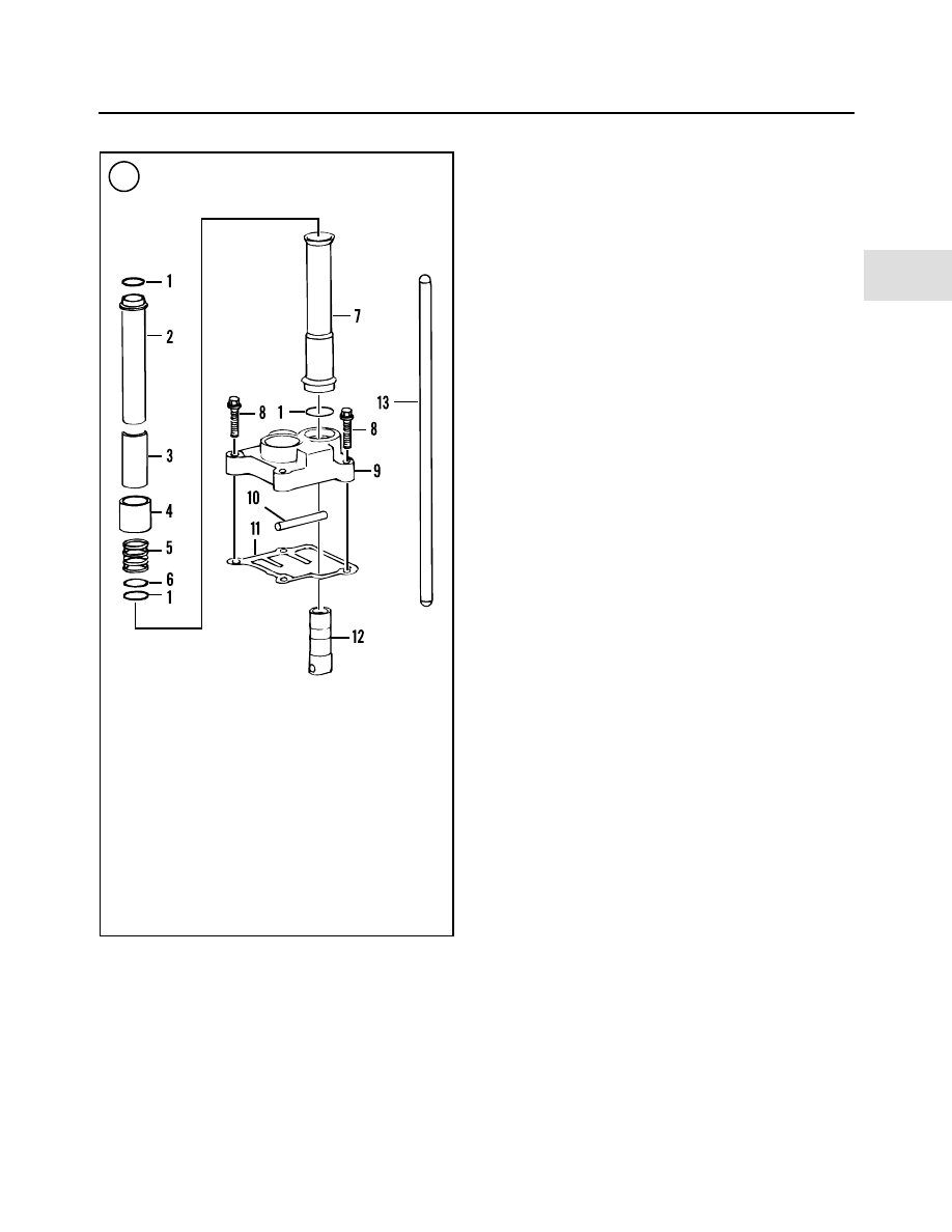
Refer to Figure 15 and Figure 16.
The rocker arm and pushrod procedures are shown with

the rear cylinder. The same procedures also apply to the
front cylinder. Any differences are noted.

The rear cylinder head is closer to the frame backbone

than the front cylinder. In some cases it may be possible to
completely remove some of the rocker arm mounting
bolts on the front cylinder that are not possible to achieve
on the rear cylinder.

Removal

1. If the engine is mounted in the frame, perform the fol-
lowing:

a. Thoroughly clean the engine of all dirt and debris.
b. Remove the seat as described in Chapter Fourteen.
c. Remove the fuel tank as described in Chapter

Seven.

d. Remove the air filter and backing plate as described

in Chapter Seven.

ENGINE

101

4

16

PUSHROD ASSEMBLY

1. O-ring
2. Upper cover
3. Spring cap

retainer

4. Spring cap
5. Spring
6. Washer
7. Lower cover
8. Allen bolt
9. Lifter cover

10. Anti-rotation pin
11. Gasket
12. Hydraulic lifter
13. Pushrod

e. Remove the exhaust system as described in Chapter

Seven.

NOTE

Always disarm the optional TSSM security
system prior to disconnecting the battery or
the siren will sound.

2. Using a crisscross pattern, loosen and remove the
rocker arm cover bolts.
3. Remove the rocker arm cover and gasket (

Figure 17

).

4. Remove both spark plugs as described in Chapter
Three to make it easier to rotate the engine by hand.
5. Remove the camshaft cover (

Figure 18

) as described

under

Camshaft Support Plate Removal

in this chapter.

6. Remove the bolt securing the crankshaft sprocket
(

Figure 19

). This is necessary to observe the timing mark

on the sprocket.

CAUTION

Do not rotate the engine using the camshaft
sprocket mounting bolt. Doing so may break
the bolt and damage the camshaft.

CAUTION

The piston must be at top dead center (TDC)
to avoid damage to the pushrods and rocker
arms in the following steps.

7A.

With the primary chain cover in place,

position the

piston for the cylinder being worked on at top dead center
(TDC) on the compression stroke as follows:

a. Support the motorcycle on a stand with the rear

wheel off the ground. See

Motorcycle Stands

in

Chapter Nine.

b. Shift the transmission into fifth gear.
c. Rotate the rear wheel in the direction of normal ro-

tation.

d. Stop rotating the rear wheel when the intake and ex-

haust valves are closed.

e. The timing mark on the camshaft and crankshaft

sprocket must be aligned as shown in

Figure 20

for

the front cylinder or

Figure 21

for the rear cylinder.

f. Look into the spark plug hole with a flashlight and

verify that the piston is at TDC.

g. Wiggle both rocker arms. There should be free play

that indicates that both valves are closed and the
piston is at top dead center (TDC) on the compres-
sion stroke. Also, the push rods should be in the un-
loaded position.

h. Reinstall the bolt and washer securing the crank-

shaft sprocket (

Figure 19

) and tighten to 24 ft.-lb.

(33 N•m).

102

CHAPTER FOUR

17

18

19

20

7B.

With the primary chain cover removed,

position the

piston for the cylinder being worked on at top dead center
(TDC) on the compression stroke as follows:

a. Shift the transmission into NEUTRAL.
b. Install the sprocket shaft nut onto the end of the left

side of the crankshaft.

c. Place a socket or wrench on the compensating

sprocket shaft nut.

d. Rotate the compensating sprocket shaft

counter-

clockwise

until the intake and exhaust valves are

closed.

e. The timing mark on the camshaft and crankshaft

sprocket must be aligned as shown in

Figure 20

for

the front cylinder or

Figure 21

for the rear cylinder.

f. Look into the spark plug hole with a flashlight and

verify that the piston is at TDC.

g. Wiggle both rocker arms. There should be free play

that indicates both valves are closed and the piston
is at top dead center (TDC) on the compression
stroke. Also, the push rods should be in the un-
loaded position.

h. Reinstall the bolt and washer securing the crank-

shaft sprocket (

Figure 19

) and tighten to 24 ft.-lb.

(33 N•m).

8. Using a crisscross pattern, completely loosen the four
bolts (A,

Figure 22

) securing the rocker arm support. The

bolts cannot be removed at this time.
9. Completely loosen the bolts securing the breather as-
sembly (B,

Figure 22

).

10. Remove the two right side rocker arm support bolts
(A,

Figure 23

) and the right side bolt (B) securing the

breather assembly.

NOTE

The left side breather assembly bolt cannot
be removed until the rocker arm housing is
removed from the cylinder head.

11. Remove the two left side rocker arm support bolts.
12. Lift up on the right side of the rocker arm housing (A,

Figure 24

) sufficiently to clear the push rods (B).

13. Carefully slide the rocker arm support out through the
right side and remove it from the cylinder head.
14. Remove the left side bolt and remove the breather as-
sembly.
15. Remove the O-ring seal (

Figure 25

) from the rocker

arm housing.
16. Mark each pushrod with its top and bottom position.
Then mark its operating position in the cylinder head.

NOTE

When removing the pushrods in the follow-
ing steps, do not intermix the parts from

ENGINE

103

4

22

23

21

24

each set. When reinstalling the original
pushrods, install them so each end faces in
its

original

operating

position.

The

pushrods develop a set wear pattern and in-
stalling them upside down may cause rapid
wear to the pushrod, lifter and rocker arm.

17. Remove the intake (A,

Figure 26

) (silver) and ex-

haust (B) (black) pushrods up through the cylinder head.
18. Remove the pushrod covers as follows:

a. Using a screwdriver, pry the spring cap retainer

(

Figure 27

) from between the cylinder head and

spring cap.

b. Slide the upper cover down (A,

Figure 28

) and re-

move the pushrod cover assembly (B) from the cyl-
inder head and the lifter cover.

c. Repeat substeps a and b for the opposite pushrod

cover.

NOTE

To clear the cylinder’s lower cooling fins,
loosen the lifter cover’s two inner Allen
bolts with a short 90

°

Allen wrench

(

Figure

29

) or a ball-end straight Allen wrench.

19. Remove the lifter cover mounting bolts (

Figure 30

)

and remove the cover.

104

CHAPTER FOUR

26

27

28

25

30

29

20. Remove the lifter cover gasket from the crankcase.

NOTE

Do not intermix the lifters when removing
them in Step 21. Mark them so they can be
installed in their original positions.

21. Remove the anti-rotation pin (A,

Figure 31

), then re-

move both hydraulic lifters (B).

22. Cover the crankcase opening with duct tape (

Figure

32

) to prevent the entry of debris.

23. Loosen the rocker housing six bolts 1/8 turn at a time
in the pattern shown in

Figure 33

.

24. Tap the rocker arm housing with a rubber mallet to
free it, then lift it off the cylinder head.

25. Remove the rocker arm housing gasket.

Installation

NOTE

Figure 34

and

Figure 35

are shown with the

engine removed from the frame to better il-
lustrate the steps.

ENGINE

105

4

31

32

33

ROCKER ARM HOUSING

TORQUE SEQUENCE

34

35

1. Position the

new

rocker arm housing gasket onto the

cylinder head so the breather channel (

Figure 34

) is cov-

ered and install the gasket (

Figure 35

).

2. Install the rocker arm housing onto the cylinder head.
3. Apply

ThreeBond

TB1342,

or

an

equivalent,

threadlocking compound to the bolt threads. Install the
rocker housing six bolts and tighten them 1/8 turn at a
time in the pattern shown in

Figure 33

. Tighten them to

120-168 in.-lb. (14-19 N•m).
4. Install a

new

O-ring seal (

Figure 25

) onto the rocker

arm housing. Apply a light coat of clean engine oil to the
O-ring.
5. Remove the duct tape from the crankcase openings.
6. Install the hydraulic lifters into the correct crankcase
receptacles with both flat surfaces (

Figure 36

) facing to-

ward the front and rear of the engine. This is necessary for
installation of the anti-rotation pin in the next step.

CAUTION

Failure to install the anti-rotational pin will
allow the lifter to rotate off the camshaft lobe
and cause severe internal engine damage.

7. Install the anti-rotation pin (

Figure 37

) and make sure

it is seated correctly within the crankcase receptacle and
against the flats on both hydraulic lifters (A,

Figure 31

).

8. If the engine’s position has been disturbed since the
rocker arm components have been removed, rotate the en-
gine until both lifters for the cylinder head being serviced
seat onto the camshaft’s lowest position (base circle). The
lifter’s top surface will be flush with the top surface of the
crankcase surface as shown in

Figure 38

.

9. Install a

new

lifter cover gasket (

Figure 39

) onto the

crankcase.

NOTE

To clear the cylinder’s lower cooling fins,
tighten the lifter cover two inner Allen bolts
with a short 90 ° Allen wrench

(

Figure 29

).

106

CHAPTER FOUR

36

37

38

39

40

10. Install the lifter cover and the mounting bolts (

Figure

30

). Tighten the bolts to 15-18 ft.-lb. (20-24 N•m).

11. Install

new

O-ring seals (

Figure 40

) onto each end of

the pushrod covers. Apply a light coat of clean engine oil
to the O-rings.
12. If the pushrod cover assembly was disassembled, re-
assemble it as described under

Pushrods

in this chapter.

CAUTION

The pushrod covers and the pushrods must
be installed in the correct location in the
cylinder head and pushrod cover as indi-
cated in

Table 3

.

13. Install the pushrod cover into the correct location in
the crankcase pushrod cover (

Figure 41

).

14. Slide the upper cover (

Figure 42

) up into the cylinder

head receptacle.
15. Compress the spring cap with a thin open end wrench
(A,

Figure 43

), or an equivalent, onto the spring cap, and

install the spring cap retainer (B). Make sure the spring
cap retainer is positioned correctly on both the upper
cover and the spring cap.
16. Repeat Steps 12-15 for the other pushrod cover.
17. Install the pushrods as follows:

CAUTION

Two different length pushrods are used in
the Twin Cam 88B engine. The black ex-
haust pushrods (A,

Figure 44

) are longer

than the silver intake pushrods (B).

a. When installing the existing pushrods, install each

pushrod in its original position and in the correct
orientation. Refer to A,

Figure 45

for intake and B,

Figure 45

for exhaust.

NOTE

Because new pushrods are symmetrical, they
can be installed with either end facing up.

ENGINE

107

4

41

42

43

44

45

b. Make sure the pushrod is centered into its respective

lifter.

NOTE

Step 18A is shown with the engine removed
to better illustrate the steps.

NOTE

The new 2002-on integral breather (A,

Fig-

ure 46

) can be installed on 2000-2001 mod-

els.

18A. On 2000-2001 models, if the old breather (B,

Figure

46

) is going to be installed, assemble it as follows:

a. If removed, install the valve onto the breather baffle

and pull the tip through from the other side (

Figure

47

) to seat it.

b. Install a

new

gasket (

Figure 48

).

c. Install a

new

filter element.

d. Hold the filter element in place and install the

breather baffle (

Figure 49

).

e. Install the cover (A,

Figure 50

) and

left side

bolt

(B).

18B. On 2002-on models, perform the following:

a. Install the filter element (

Figure 51)

onto the

breather.

108

CHAPTER FOUR

46

47

48

49

50

51

b. Install the breather assembly (A,

Figure 52

) onto

the rocker arm support and install the left side bolt
(B).

19. From the right side, slide the rocker arm support (A,

Figure 24

) onto the housing, past the pushrods (B). Do

not forget to install the breather assembly left side bolt
(

Figure 53

). This bolt cannot be installed after the rocker

arm support is in place on the cylinder head.

20. Lift up on the left side of the rocker arm support and
install the two right side bolts (A,

Figure 23

) and the right

side breather assembly bolt (B). Do not tighten at this
time.

21. Install the two left side rocker arm support bolts (

Fig-

ure 54

).

CAUTION

To avoid damaging a pushrod, rocker arms
or valves, tighten the rocker arm support
mounting bolts evenly and in a crisscross
pattern. When tightening the mounting
bolts, spin each pushrod by hand to ensure
the rocker arm support is being tightened
evenly. If one or both pushrods cannot be ro-
tated, loosen the mounting bolts and deter-
mine the cause.

22. Tighten the rocker arm support assembly and bolts
evenly in a crisscross pattern to 18-22 ft.-lb. (25-30 N•m).

23. Make sure the pushrod cover O-rings are correctly
seated in the cylinder head and lifter cover. Depress the
spring cap and install the spring cap retainer. Make sure
the spring cap retainer is correctly seated (

Figure 55

). Re-

peat for the remaining pushrod covers.

24. Install a

new

rocker arm cover gasket (

Figure 56

).

25. Install the rocker arm cover (

Figure 57

).

NOTE

There are two different length bolts (

Figure

58

) securing the rocker arm cover.

ENGINE

109

4

53

54

56

52

55

26. Apply ThreeBond TB1342 (blue) or an equivalent
threadlocking compound to the bolt threads. Install the
rocker arm cover six bolts and tighten them 1/8 turn at a
time in the sequence shown in

Figure 58

. Tighten them to

15-18 ft.-lb. (20-24 N•m).
27. Install the camshaft cover (

Figure 59

) as described

under

Camshaft Support Plate Removal

in this chapter.

28. Install both spark plugs as described in Chapter Three.

Rocker Arm Disassembly/Assembly

1. Before removing the rocker arms (

Figure 60

), mea-

sure the rocker arm end clearance as follows:

a. Insert a feeler gauge between the rocker arm and the

inside rocker arm cover boss as shown in

Figure 61

.

Refer to

Table 2

.

b. Record the measurement.
c. Repeat for each rocker arm.
d. Replace the rocker arm and/or the rocker arm

support if necessary.

2. Prior to disassembling the rocker arms, mark each one
with an IN (intake) or EX (exhaust) (

Figure 62

) to ensure

they are installed in their original positions.
3. Remove the rocker arm shafts (A,

Figure 63

) and re-

move the rocker arms (B).
4. Clean all parts in solvent. Blow compressed air
through all oil passages.
5. Install the rocker arm shaft (A,

Figure 64

) part way

into the rocker arm support (B) in its original position.
6. Install a rocker arm (C,

Figure 64

) into its original po-

sition and push the shaft part way through the rocker arm.
7. Align the notch in the rocker arm shaft (A,

Figure 65

)

with the mating bolt hole (B) in the support and install the
shaft all the way. Check for correct alignment (

Figure 66

).

8. Repeat Step 6 and Step 7 for the remaining rocker arm
and shaft.

Rocker Arm Component Inspection

When measuring the rocker arm components, compare

the actual measurements to the specifications in

Table 2

.

Replace any part that is damaged or out of specification as
described in this section.
1. Inspect the rocker arm pads and ball sockets (

Figure

67

) for pitting and excessive wear.

2. Examine the rocker arm shaft (

Figure 68

) for scoring,

ridge wear or other damage. If these conditions are pres-
ent, replace the rocker arm shaft. If the shaft does not
show any wear or damage, continue with Step 3.
3. Check the rocker arm bushing (

Figure 69

) for wear or

scoring.

110

CHAPTER FOUR

57

58

ROCKER ARM COVER

TORQUE SEQUENCE

Short bolts

Long bolts

59

ENGINE

111

4

60

ROCKER ARM ASSEMBLY

1. Bolt
2. Rocker arm cover
3. Gasket
4. Bolt
5. Breather cover*
6. Gasket*
7. Valve*
8. Breather baffle*
9. Filter element*

10. Gasket*
11. Bushing
12. Rocker arm

Intake—front cylinder
Exhast—rear cylinder

13. Rocker arm shaft
14. Washer
15. Rocker arm support
16. Rocker arm

Intake—rear cylinder
Exhaust—front cylinder

17. O-ring seal
18. Rocker arm housing
19. Gasket

61

62

*Items 5-10 are combined into an
integral unit on 2002-on models.

4. Measure the rocker arm shaft diameter (

Figure 70

)

where it contacts the rocker arm bushing and rocker arm
support. Measure both ends of the shaft. Record each
measurement.
5. Measure the rocker arm bushing inside diameter (

Fig-

ure 71

) and the rocker arm support (

Figure 72

) inside di-

ameter. Record each measurement.
6. Subtract the measurements taken in Step 4 from those
taken in Step 5 to obtain the following rocker arm shaft
clearances:

a. Shaft-to-rocker arm support.
b. Shaft-to-rocker arm bushing.

7. Replace the rocker arm bushings or the rocker arm
support if the clearance exceeds the specifications. Rocker
arm bushing replacement is described in this chapter.
8. Inspect the rocker arm shaft contact surfaces in the
rocker arm support for wear or elongation.
9. Inspect the gasket surface of the rocker arm cover for
damage or warp.
10. Inspect the rocker arm support (

Figure 73

) for dam-

age or warp.
11. Inspect both gasket surfaces of the rocker arm hous-
ing for damage or warp.
12. Inspect the lifter cover (

Figure 74

) for cracks or dam-

age.

112

CHAPTER FOUR

63

64

65

66

67

68

Rocker Arm Bushing Replacement

Each rocker arm is equipped with two bushings (

Figure

69

). Replacement bushings must be reamed after installa-

tion. Use the rocker arm bushing line reamer (JIMS part No.
94804-57). If the correct size reamer is unavailable, have the
bushings replaced by a Harley-Davidson dealership.

NOTE

Since the new bushings must be reamed, re-
move one bushing at a time. The opposite
bushing is then used as a guide to ream the
first bushing.

1. Press one bushing (

Figure 69

) out of the rocker arm.

Do not remove the second bushing. If the bushing is diffi-
cult to remove, perform the following:

a. Thread a 9/16 × 18 tap into the bushing.
b. Support the rocker arm in a press so the tap is at the

bottom.

c. Insert a mandrel through the top of the rocker arm

and seat it on top of the tap.

d. Press on the mandrel to force the bushing and tap

out of the rocker arm.

e. Remove the tap from the bushing and discard the

bushing.

ENGINE

113

4

69

70

71

72

73

74

2. Position the new bushing with the split portion facing
toward the top of the rocker arm.
3. Press the new bushing into the rocker arm until the bush-
ing’s outer surface is flush with the end of rocker arm bore.
4. Ream the new bushing with the bushing line reamer as
follows:

a. Mount the rocker arm in a vise with soft jaws so the

new bushing is at the bottom.

CAUTION

Only turn the reamer clockwise. Do not ro-
tate the reamer counterclockwise or the
reamer and bushing will be damaged.

b. Mount a tap handle on top of the reamer and insert

the reamer into the bushing. Turn the reamer

clock-

wise

until it passes through the new bushing and re-

move it from the bottom side.

5. Remove the rocker arm from the vise and repeat Steps
1-3 to replace the opposite bushing. The first bushing now
serves as a guide to ream the second bushing.
6. After installing and reaming both bushings, clean the
rocker arm assembly in solvent. Then clean it with hot,
soapy water and rinse it with clear, cold water. Dry it with
compressed air.
7. Measure the inside diameter of each bushing. When
properly reamed, the bushings must provide the shaft
clearance listed in

Table 2

.

Pushrod Inspection

1. Clean the pushrods in solvent and dry them with com-
pressed air.
2. Check the pushrods for bending, cracks and worn or
damaged ball heads (

Figure 75

).

3. Replace any damaged pushrods.

CYLINDER HEAD

The cylinder head procedures are shown on the rear cyl-

inder (

Figure 76

). The same procedures also relate to the

front cylinder. Any differences are noted.

NOTE

The following procedures are shown with the
engine removed to better illustrate the steps.

Removal

1. Remove the rocker arm assemblies and pushrods as
described in this chapter.

114

CHAPTER FOUR

75

76

CYLINDER HEAD

1. Valve keepers
2. Upper retainer
3. Inner valve spring
4. Outer valve spring
5. Oil seal
6. Lower retainer
7. Valve guide
8. Bolt—short
9. Bolt—long

10. Cylinder head
11. Valve seat
12. Valve
13. Gasket

2. Using a crisscross pattern, loosen the four cylinder
head bolts (Figure 77) 1/8 turn at a time. Remove the four
bolts and note the position of the short and long bolts.
3. Tap the cylinder head with a rubber mallet to free it,
then lift it off the cylinder.
4. Remove the cylinder head gasket.
5. Remove the two O-rings and the cylinder head dowel
pins (Figure 78).
6. Repeat these steps to remove the opposite cylinder head.

Inspection

1. Thoroughly clean the outside of the cylinder head. Use
a stiff brush, soap and water to remove all debris from the
cooling fins (Figure 79). If necessary, use a piece of wood
and scrape away any lodged dirt. Clogged cooling fins can
cause overheating and lead to engine damage.
2.

Without removing the valves

, use a wire brush to re-

move all carbon deposits from the combustion chamber.
Use a fine wire brush dipped in solvent or make a scraper
from hardwood. Be careful not to damage the head, valves
or spark plug threads.

CAUTION

Cleaning the combustion chamber with the
valves removed can damage the valve seat
surfaces. A damaged or even slightly
scratched valve seat will cause poor valve
seating.

3. Examine the spark plug threads in the cylinder head for
damage. If there is minor damage or if the threads are dirty
or clogged with carbon, use a spark plug thread tap (Figure
80
) to clean the threads following the manufacturer’s in-
structions. If there is severe thread damage, restore the
threads by installing a steel thread insert. Purchase thread
insert kits at an automotive supply store or have the kits in-
stalled by a Harley-Davidson dealership or machine shop.

NOTE

When using a tap to clean spark plug
threads, coat the tap with an aluminum
tap-cutting fluid or kerosene.

NOTE

Aluminum spark plug threads are commonly
damaged due to galling, cross-threading
and over-tightening. To prevent galling, ap-
ply an antiseize compound on the plug
threads before installation and do not
overtighten.

4. After all carbon is removed from the combustion
chambers and valve ports, and if the spark plug thread

ENGINE

115

4

77

78

79

80

hole has been repaired, clean the entire head in solvent.
Dry it with compressed air.

5. Examine the crown on the piston (Figure 81). The
crown should show no signs of wear or damage. If the
crown appears pecked or spongy-looking, also check the
spark plug, valves and combustion chamber for aluminum
deposits. If these deposits are found, the cylinder has
overheated. Check for a lean fuel mixture or other condi-
tions that could cause preignition.

6. Check for cracks in the combustion chamber, the in-
take port (Figure 82) and the exhaust port (Figure 83).
Replace a cracked head if welding can not repair it.

7. Inspect the exhaust pipe mounting bolts (Figure 84) for
damage. Repair the threads with a tap if they are damaged.

CAUTION

If the cylinder head is bead-blasted, clean
the head thoroughly with solvent, then with
hot soapy water. Residual grit seats in small
crevices and other areas, and can be hard to
get out. Also run a tap through each exposed
thread to remove grit from the threads. Resi-
due grit left in the engine will cause prema-
ture wear.

8. Thoroughly clean the cylinder head.

9. Measure for warp by placing a straightedge across the
gasket surface at several points and attempting to insert a
feeler gauge between the straightedge and cylinder head
at each location (Figure 85). Maximum allowable warp is
in Table 2. Distortion or nicks in the cylinder head surface
could cause an air leak and overheating. If warp exceeds
the limit, resurface or replace the cylinder head. Consult a
Harley-Davidson dealership or machine shop experi-
enced in this type of work.

10. Check the rocker arm housing mating surfaces for
warp (Figure 86) using the procedure in Step 9.

11. Make sure the breather channel is clear at each end
(Figure 87).

116

CHAPTER FOUR

81

82

83

84

85


Content      ..     10      11      12      13     ..