Harley Davidson Softail 2000-2005. Service manual - page 9
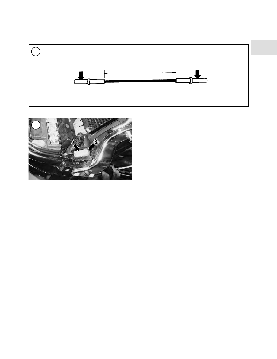
wire and two Deutsch sockets (H-D part No. 72191-94),
shown in Figure 37, are required.
To retrieve the diagnostic code(s), perform the follow-
ing:
1. Remove the seat as described in Chapter Fourteen.
2. Lift the data link connector up and off the mounting
bracket.
3. Remove the protective cover from the data link con-
nector.
4. Install the jumper wire onto pins No. 1 (light
green/red) and No. 2 (black) on the data link connector.
5. Turn the ignition/light key switch to the IGNITION
position. After approximately eight seconds, the different
systems enter the diagnostic codes:
a. The check engine light begins with a ready signal,
which is a series of six rapid flashes, approximately
three per second. The ready signal indicates the
check engine light is ready to flash a diagnostic
code.
b. The ready signal is followed by a two-second pause.
c. Then the system flashes the first digit of the stored
diagnostic code. The check engine light will illumi-
nate for one second then turn off for one second. Re-
cord the number of flashes. For example, two
flashes indicate the first digit is two.
d. The system pauses for two seconds then flashes the
second digit of the diagnostic code. record the num-
ber of flashes. For example, five flashes indicate the
second digit is five. In this example, the first code is
25, or a problem with the rear cylinder ignition coil.
e. If more than one code is present, the system will
pause for two seconds then flash the ready signal,
which is a series of six rapid flashes.
f. The system pauses for two seconds, then flashes the
first digit of the next diagnostic code, followed by
the second digit.
6. The system displays the stored codes sequentially until
each diagnostic code has been displayed. Then the system
repeats the codes. The check-engine light repeats the
stored codes until the jumper wire is disconnected. When
the codes repeat, all stored codes have been displayed.
Turn the ignition switch to the OFF position and remove
the jumper wire from the data link connector.
7. Refer to diagnostic codes in Table 3 to locate the prob-
lem.
8. Install the protective cover onto the data link connector
and fit the data link connector onto the mounting bracket.
9. Install the seat as described in Chapter Fourteen.
Fuel Injected Models
Diagnostic codes retrieval
NOTE
Diagnostic codes can only be cleared by a
Harley-Davidson dealership.
1. Remove the seat as described in Chapter Fourteen.
2. Lift the data link connector (A, Figure 38) up and off
the mounting bracket.
3. Remove the protective cover (B, Figure 38) from the
data link connector.
TROUBLESHOOTING
53
2
37
2 in.
38