Harley Davidson Softail 2000-2005. Service manual - page 7
 

  Главная      Harley Davidson     Harley Davidson Softail 2000-2005. Service manual


Search            copyright infringement  


Content      ..     5      6      7      8     ..


Harley Davidson Softail 2000-2005. Service manual - page 7


c. If wear or damage is found, replace the brake hose/

line assembly.

12. Install the brake hose/line assembly,

new

steel/rubber

sealing washers and banjo bolts in the reverse order of re-
moval. Note the following:

a. Install

new

steel/rubber sealing washers against the

side of each hose fitting.

b. Carefully install the clips and guides to hold the brake

hose in place.

c. On FXSTDSE2 models, tighten the bolt securing the

mounting plate to 96-120 in.-lb. (11-14 N•m).

d. Tighten the banjo bolts to 17-22 ft.-lb. (23-30

N•m).

e. Refill the front master cylinder with clean brake fluid

clearly marked DOT 5. Bleed the front brake system
as described in Chapter Thirteen.

WARNING

Do not ride the motorcycle until the front
brakes operate correctly with full hydraulic
advantage.

Rear Brake Hose and Line
Removal/Installation

The replacement of the rear brake hose/line assembly is

the same as on all previous models.

BRAKE DISC

(FXSTDSE2 AND FLSTFSE MODELS)

Inspection

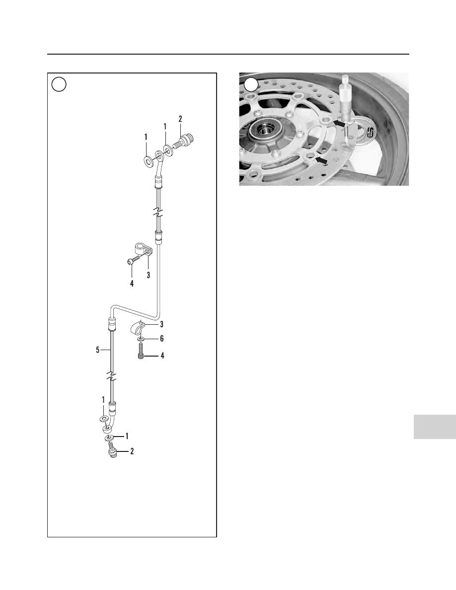
Check the floating disc fasteners (Figure 85) for dam-

age or looseness. If any are loose or damaged, replace the
disc.

2004-2005 MODEL SERVICE INFORMATION

599

15

84

FRONT BRAKE HOSE

(FLSTFSE MODELS)

1. Steel/rubber sealing washer
2. Banjo bolt
3. Clamp
4. Bolt
5. Brake hose assembly
6. Washer
7. Bolt

85

600

SUPPLEMENT

Table 21 BRAKE SYSTEM TORQUE SPECIFICATIONS

ft.-lb.

in.-lb.

N•m

Brake line banjo bolts

17-22

23-30

Brake line mounting plate

96-120

11-14

CHAPTER FOURTEEN

BODY

SEAT

Removal/Installation (FLSTFSE Models)

1. Place the motorcycle on level ground on the jiffy stand.
2. Remove the T-30 Torx bolt and washer securing the tail
section of the seat.
3. Lift up on the rear of the seat, pull toward the rear and dis-
engage the seat from the frame.
4. Make sure the screws securing the seat to the seat pan are
tight.
5. Installation is the reverse of removal. Note the following:

a. Push the seat forward and engage the front bracket

into the slot in the frame backbone.

b. Pull up on the front of the seat to ensure the seat front

hook is secured in the frame backbone slot.

c. Tighten the Torx screw securely.

Disassembly/Assembly (FLSTFSE Models)

1. Remove the seat as previously described in this section.
2. Turn the seat upside down on blankets on the work bench.
3. Remove the six screws and two washers (front screws
only) securing the seat pad to the seat pan. Remove the
seat pad.
4. If necessary, remove the four screws securing the right
and left side trim pieces. Remove the trim pieces.
5. If necessary, remove the two screws securing the rear
trim piece and remove it from the seat pan.
6. If necessary, remove the two screws securing the tail
piece to the seat pan and remove the tail piece.
7. Installation is the reverse of removal. Tighten all screws
securely.

Removal/Installation
(FLSTFI 15th Anniversary Models)

1. Place the motorcycle on level ground on the jiffy stand.
2. Remove the bolt and washers, on each side, securing the
passenger seat strap. Remove the seat strap.
3. Remove the special screw securing the rear section of
the seat.
4. Lift up on the rear of the seat, pull toward the rear and dis-
engage the seat from the frame.
5. Installation is the reverse of removal. Note the following:

a. Push the seat forward and engage the front bracket

into the slot in the frame backbone.

b. Pull up on the front of the seat to ensure the seat front

hook is secured in the frame backbone slot.

c. Tighten the special screw securely.
d. Install the passenger seat strap and tighten the bolts to

21-27 ft.-lb. (29-37 N•m).

FRONT FENDER

Removal/Installation
(FLSTN and FLSTFSE Models)

Follow the procedure for FLSTC and FLSTF models in

Chapter Fourteen.

Removal/Installation
(FXSTDSE2 Models)

Follow the procedure for FXSTD models in Chapter

Fourteen.

REAR FENDER

Removal/Installation
(FLSTN and FLSTFSE Models)

Follow the procedure for FLSTS models in Chapter

Fourteen.

On FLSTN models, if necessary, remove the three

screws and washers securing the luggage rack to the rear

fender and remove it. Tighten the screws securely.

FOOTBOARDS AND FOOTRESTS

Removal/Installation
(FLSTN Models)

Refer to Figure 86 and follow the procedure in Chapter

Fourteen.

2004-2005 MODEL SERVICE INFORMATION

601

15

86

FOOTBOARDS AND FOOTRESTS

(2005 FLSTN MODELS)

1. Footrest
2. Bolt
3. Nut
4. Spring washer
5. Footrest bracket–

passenger (right
side)

6. Bolt
7. Bolt
8. Bolt
9. Footrest bracket–

passenger (left
side)

10. Support bracket
11. Bolt
12. Washer
13. Snap ring
14. Clevis pin
15. Footboard pad
16. Footboard cover
17. Footboard base
18. Locknut
19. Hinge bolt
20. Bolt
21. Mounting bracket

(footboard–right
side)

22. Mounting bracket

(footboard, shift
lever stand [all
models]–left side)

23. Bolt
24. Mounting bracket

(footbard and brake
lever–right side)

25. Bolt

reading is low, check for an undercharged battery, or an
open field winding or armature in the starter.

Solenoid Testing (Bench Tests)

This test requires a fully charged 12-volt battery and

three jumper wires.
1. Remove the starter (A, Figure 17) as described in
Chapter Eight.

NOTE

The solenoid (B,

Figure 17

) must be installed

on the starter during the following tests.

2. Disconnect the C field wire terminal (C, Figure 17)
from the solenoid before performing the following tests.
Insulate the end of the wire terminal so that it cannot short
out on any of the test connectors.

CAUTION

Because battery voltage is being applied di-
rectly to the solenoid and starter in the fol-
lowing tests, do not leave the jumper cables
connected to the solenoid for more than
three-five seconds; otherwise, the voltage
will damage the solenoid.

NOTE

Thoroughly read the following procedure to
become familiar with and understand the
procedures and test connections, then per-
form the tests in the order listed and without
interruption.

3. Perform the solenoid pull-in test as follows:

a. Connect one jumper wire from the negative battery

terminal to the solenoid C terminal (Figure 18).

b. Connect one jumper wire from the negative battery

terminal to the solenoid housing (ground) (Figure
18
).

c. Touch a jumper wire from the positive battery ter-

minal to the starter 50 terminal (Figure 18). The
pinion shaft (D, Figure 17) should pull into the
housing.

d. Leave the jumper wires connected and continue

with Step 4.

4. To perform the solenoid hold-in test, perform the fol-
lowing:

a. With the pinion shaft pulled in (Step 3), disconnect

the C terminal jumper wire from the negative bat-
tery terminal and connect it to the positive battery
terminal (Figure 19). The pinion shaft should re-
main in the housing. If the pinion shaft returns to its
original position, replace the solenoid.

TROUBLESHOOTING

45

2

17

18

19

SOLENOID PULL-IN TEST

C terminal

Battery

50 terminal

Solenoid

Battery

50 terminal

Solenoid

C terminal

Starter

Starter

SOLENOID HOLD-IN TEST

b. Leave the jumper wires connected and continue

with Step 5.

5. To perform the solenoid return test, perform the fol-
lowing:

a. Disconnect the jumper wire from the starter 50 ter-

minal (Figure 20); the pinion shaft should return to
its original position.

b. Disconnect all of the jumper wires from the sole-

noid and battery.

6. Replace the solenoid if the starter shaft failed to oper-
ate as described in Steps 3-5. See

Solenoid Replacement

in Chapter Eight.

Starter Relay Removal/Testing/Installation

Check the starter relay operation with an ohmmeter,

jumper wires and a fully charged 12-volt battery.
1. Remove the seat as described in Chapter Fourteen.
2. Disconnect the negative battery cable as described in
Chapter Eight.
3. Carefully pull the top cover (Figure 21) from the fuse
block.
4. Pull straight up and remove the starter relay (Figure
22
) from the fuse block.

CAUTION

The battery negative lead must be connected
to the relay terminal No. 85 to avoid internal
diode damage.

5. Connect an ohmmeter and 12-volt battery between the
relay terminals shown in Figure 23. This setup will ener-
gize the relay for testing.
6. Check for continuity through the relay contacts using
an ohmmeter while the relay coil is energized. The correct
reading is 0 ohm. If resistance is excessive or if there is no
continuity, replace the relay.
7. If the starter relay passes this test, reconnect the relay.
8. Install the starter relay (Figure 22) into the fuse block.
Press it in until it bottoms.
9. Install the top cover onto the fuse block and press it on
until it latches correctly.
10. Connect the negative battery cable as described in
Chapter Eight.
11. Install the seat as described in Chapter Fourteen.

CHARGING SYSTEM

The charging system consists of the battery, alternator

and a solid state voltage regulator/rectifier.

The alternator generates alternating current (AC) which

the rectifier converts to direct current (DC). The regulator

maintains the voltage to the battery and load (lights,
ignition and accessories) at a constant voltage despite
variations in engine speed and load.

A malfunction in the charging system generally causes

the battery to remain undercharged.

Service Precautions

Before servicing the charging system, observe the

following precautions to prevent damage to any charg-
ing system component:
1. Never reverse battery connections.
2. Do not short across any connection.
3. Never start the engine with the alternator discon-
nected from the voltage regulator/rectifier unless in-
structed to do so during testing.

46

CHAPTER TWO

20

SOLENOID RETURN TEST

50 terminal

Starter

Battery

Solenoid

C terminal

21

4. Never attempt to start or run the engine with the bat-
tery disconnected.
5. Never attempt to use a high-output battery charger to
help start the engine.
6. Before charging the battery, remove it from the motorcy-
cle as described in Chapter Eight.
7. Never disconnect the voltage regulator/rectifier connec-
tor with the engine running. The voltage regulator/rectifier
(Figure 24) is mounted on the front frame cross member.
8. Do not mount the voltage regulator/rectifier unit in an-
other location.
9. Make sure the negative battery terminal is connected to
the engine and frame.

Troubleshooting Sequence

If the battery is discharged, perform the following pro-

cedures as listed:
1. Test the battery as described in Chapter Eight. Charge
the battery if necessary. If the battery will hold a charge
while riding, perform the

Charging System Output Test

.

2. If the charging system output is with specification, de-
termine the total amount of current demand by the electri-
cal system and all accessories as described under

Electrical System Current Load Test

.

3. If the charging system output exceeds the current de-
mand and the battery continues to not hold a charge, per-
form the

Battery Current Draw Test

.

4. If the charging system output is not within specifica-
tion, test the stator and voltage regulator as described in
this section.

Charging System Output Test

This test requires a load tester.

1. To perform this test, the battery must be fully charged.

NOTE

When using a load tester, refer to the manu-
facturer’s instructions. To prevent tester
damage caused by overheating, do not leave
the load switch ON for more than 20 sec-
onds at a time.

2. Connect the load tester negative and positive leads to
the battery terminals. Then place the load tester’s induc-
tion pickup over the circuit breaker to voltage regulator
wire (Figure 25).
3. Start the engine and slowly bring the speed up to 3000
rpm while reading the load tester scale. With the engine
running at 3000 rpm, operate the load tester switch until

TROUBLESHOOTING

47

2

24

23

12-volt battery

Ohmmeter

86

87A

85

87

30

22

the voltage scale reads 13.0 volts. The tester should show
a regulated (DC) current output reading as follows:

a. Carbureted models: 34-40 amps.
b. Fuel-injected models: 41-48 amps.

4. With the engine still running at 3000 rpm, turn the load
off and read the load tester voltage scale. Battery voltage
should not exceed 15 volts. Turn the engine off and dis-
connect the load tester from the motorcycle.
5. Perform the

Stator Test

described in this section. If the

stator tests acceptable, a defective voltage regulator/recti-
fier or a wiring short circuit is indicated.

Make sure to eliminate the possibility of a poor connec-

tion or damaged wiring before replacing the voltage regu-
lator/rectifier.

Electrical System Current Load Test

This test, requiring a load tester, measures the total cur-

rent load of the electrical system and any additional acces-
sories while the engine is running. Perform this test if the
battery keeps being discharged, yet the charging system
output is within specifications.

If aftermarket electrical components have been added

to the motorcycle, the increased current demand may ex-
ceed the charging systems capacity and result in a dis-
charged battery.

NOTE

When using a load tester, refer to the manu-
facturer’s instructions. To prevent tester
damage caused by overheating, do not leave
the load switch ON for more than 20 sec-
onds at a time.

1. Connect a load tester to the battery as shown in

Figure

26

.

2. Turn the ignition switch ON but do not start the engine.
Then turn on

all

electrical accessories and switch the

headlight beam to HIGH.
3. Read the ampere reading (current draw) on the load
tester and compare it to the test results obtained in the

Charging System Output Test

in this section. The charging

system output test results (current reading) must exceed
the electrical system current load by 3.5 amps for the bat-
tery to remain sufficiently charged.
4. If aftermarket accessories have been added to the mo-
torcycle, disconnect them and repeat Step 3. If the electri-
cal system current load is now within the specification,
the problem is with the additional accessories.
5. If no accessories have been added to the motorcycle, a
short circuit may be causing the battery to discharge.

Stator Test

1. With the ignition switch turned OFF, disconnect the
regulator/rectifier connector (

Figure 27

) below the

mounting bracket.
2. Switch an ohmmeter to its R ×1 scale. Then connect it
between either stator socket and ground. The correct ohm-
meter reading is infinity. Any other reading indicates a
grounded stator. Repeat this test for the other stator
socket.

48

CHAPTER TWO

25

Load tester

To voltage
regulator

To circuit breaker

(DC output)


Content      ..     5      6      7      8     ..