Harley Davidson Softail 2000-2005. Service manual - page 8
 

  Главная      Harley Davidson     Harley Davidson Softail 2000-2005. Service manual


Search            copyright infringement  


Content      ..     6      7      8      9     ..


Harley Davidson Softail 2000-2005. Service manual - page 8


b. Remove the locknuts and washers from both U-bolt

clamps and remove both clamps.

c. Move the frame cover bracket forward and remove

it from the frame.

7. Install by reversing these removal steps. Tighten all
bolts and nuts securely.

Removal/Installation
(FLSTFSE Models)

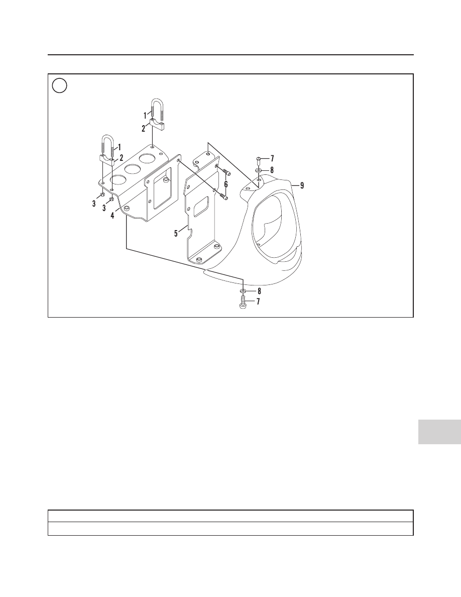
Refer to Figure 88.

1. Support the motorcycle with the front wheel off the
ground. See

Motorcycle Stands

in Chapter Nine.

2. Remove the two lower screws and nylon washers then
the two upper screws and nylon washers securing the
front spoiler to the voltage regulator mounting bracket.
3. Carefully move the front spoiler forward and away
from the voltage regulator.
4. To remove the voltage regulator mounting bracket, re-
move the screws and remove the voltage regulator bracket
from the front spoiler mounting bracket. Remove the
bracket.
5. To remove the front spoiler mounting bracket, remove
the locknuts and washers from both U-bolt clamps and re-
move both clamps. Move the front spoiler bracket down
and remove it from the frame.

2004-2005 MODEL SERVICE INFORMATION

603

15

88

FRONT SPOILER (FLSTFSE MODELS)

1. U-bolt
2. Bracket
3. Locknut
4. Spoiler mounting

bracket

5. Voltage regulator

bracket

6. Bolt
7. Screw
8. Washer–nylon
9. Front spoiler

Table 22 BODY TORQUE SPECIFICATIONS

ft.-lb.

in.-lb.

N•m

Passenger seat strap bolts

21-27

29-37

610

WIRING DIAGRAMS

Fuel gauge (all

models except

FXSTD)

Fuel level

sender

(FXSTD only)

65

154

141

117

To 13

21

Neutral

indicator

High beam

indicator

Position

light

(HDI only)

Left turn

signal

indicator

Right turn

signal

indicator

Oil press.

indicator

Headlight

Right

passing

light

Left

passing

light

Right

front turn

signal

Left

front turn

signal

Tach. Connector,
pin 6 speedomtr.

(optional)

Left

turn signal

switch

Emergency

stop

switch

Starter

switch

74

13

Main

harness

73

108

31

38

Lights

15A

Instr

15A

Acc

15A

Fuse

15A

Ign.

15A

Right

turn signal

switch

Function/

tripmeter

reset switch

Passing

lights

switch

Horn

122

24

22

Horn

switch

Front

brake

switch

Headlight

dimmer switch

High

Low

Speed

sensor

Fuel

level

sender

Off

Acc

Ign

Ignition

switch

33

39

Electronic

speedometer

To data

link

91

30

2

3

4

6

5

8

7

1

Turn signal

module

2000 FLSTS AND FXSTD DOMESTIC AND HDI MODELS

WIRING DIAGRAMS

611

17

Neutral

indicator

switch

Oil

pressure

switch

Left
rear turn
signal

18

32

32

93

19

Gnd 3

Gnd

1 & 2

Battery

Fender tip
light for US
FLSTC only

Spark

plugs

Crank

position

sensor

Cam

position

sensor

79

14

121

120

131

Diagram Key

Connectors

Ground

Frame ground

No connection

Connection

Rear

brake

switch

46

61

128

Stator

Ignition

coil

Starter

solenoid/

Motor

10

11

(Gray)

(Black)

Ignition module

Circuit
breaker
30A

Manifold

air press.

sensor

80

134

Bank angle

sensor

Tail
light

Right
rear turn
signal

License
plate lights
(FXSTD only)

7

83

2

3

4

6

5

12

11

10

9

8

7

1

2

3

4

6

5

12

11

10

9

8

7

1

Voltage

regulator

B

A

C

Starter

relay

a

86 85

87

30

87

3. Switch an ohmmeter to its R ×1 scale. Then connect it
between both stator sockets at the crankcase. The correct
ohmmeter reading should be less than 0.5 ohm. If the re-
sistance is not as specified, replace the stator.

4. Check stator AC voltage output as follows:

a. Connect an AC voltmeter across the stator pins.

b. Start the engine and slowly increase engine speed to

2000 rpm. The AC output on carbureted models is

16-20 VAC per 1000 rpm. The AC output on fuel in-
jected models is19-26 VAC per 1000 rpm.

c. If the AC voltage output reading is below the speci-

fied range, the problem is probably a defective
stator or rotor. If these parts are not damaged, per-
form the

Charging System Output Test

in this sec-

tion.

5. Reconnect the regulator/rectifier connector.

Voltage Regulator Ground Test

The voltage regulator must be grounded to the mount-

ing bracket and the frame for proper operation as shown in

Figure 28

.

1. Switch an ohmmeter to the R ×1 scale.
2. Connect one ohmmeter lead to a good engine or frame
ground and the other ohmmeter lead to the regulator base.
Read the ohmmeter scale. The correct reading is 0 ohm.
Note the following:

a. If there is low resistance (0 ohm), the voltage regu-

lator is properly grounded.

b. If there is high resistance, remove the voltage regu-

lator and clean its frame mounting points.

3. Check the voltage regulator connector (

Figure 27

) and

make sure it is clean and tightly connected.

Voltage Regulator Bleed Test

1. Disconnect the voltage regulator connector (

Figure

27

).

NOTE

Do not disconnect the wire from the voltage
regulator to the circuit breaker.

2. Connect one probe of a 12-volt test lamp to a good
frame or engine ground.
3. Connect the other test lamp probe to one of the voltage
regulator pins, then to the other pin.
4. If the test lamp lights, replace the voltage regulator.
5. If the voltage regulator passes this test, reconnect the
voltage regulator connector at the engine crankcase.

Battery Current Draw Test

This test measures the current draw or drain on the bat-

tery when all electrical systems and accessories are off.
Perform this test if the battery will not hold a charge when
the motorcycle is not being used. A current draw that ex-
ceeds 5.5 mA will discharge the battery. The ECM (1
mA), voltage regulator (0.5 mA), TSM (0.5 mA), TSSM
disarmed (0.5 mA) and TSSM armed (3.0 mA) account

TROUBLESHOOTING

49

2

27

26

28

LOAD TEST

Load
Tester

Battery

for a 5.0 mA current draw. The battery must be fully
charged to perform this test.

1. Disconnect the negative battery cable as described in
Chapter Eight.

2. Connect an ammeter between the negative battery termi-
nal and the battery ground cable as shown in

Figure 29

.

3. With the ignition switch, lights and all accessories turned
off, read the ammeter. If the current drain exceeds 5.5 mA,
continue with Step 4.

4. Refer to the wiring diagrams at the end of the manual for
the necessary model. Check the charging system wires and
connectors for shorts or other damage.

5. Unplug each electrical connector separately and check
for a reduction in the current draw. If the meter reading
changes after a connector is disconnected, the source of the
current draw has been found. Check the electrical connectors
carefully before testing the individual component.

6. After completing the test, disconnect the ammeter and re-
connect the negative battery cable.

IGNITION SYSTEM

All models are equipped with a transistorized ignition

system. This solid-state system uses no contact breaker
points to trigger the ignition. Refer to the wiring diagrams
at the end of this manual for the necessary model and year.

Because of the solid-state design, problems with the

transistorized system are rare. If a problem occurs, it gen-
erally causes a weak spark or no spark at all. An ignition
system with a weak spark or no spark is relatively easy to
troubleshoot. It is difficult, however, to troubleshoot an
ignition system that only malfunctions when the engine is
hot or under load.

Ignition System Precautions

The following measures must be taken to protect the ig-

nition system:

1. Never disconnect any of the electrical connectors
while the engine is running.

2. Apply dielectric grease to all electrical connectors
prior to reconnecting them. This will help seal out mois-
ture.

3. Make sure all electrical connectors are free of corro-
sion and are completely coupled to each other.

4. The ignition module, or electronic control module
must always be mounted securely to the mounting bracket
under the seat (

Figure 30

, typical).

Troubleshooting Preparation

1. Refer to the wiring diagrams at the end of this manual
for the specific model.

2. Check the wiring harness for visible signs of damage.

3. Make sure all connectors are properly attached to each
other and locked in place.

4. Check all electrical components for a good ground to
the engine.

5. Check all wiring for short circuits or open circuits.

6. Remove the rear fender inner panel as described in
Chapter Fourteen.

7. Check for a damaged ignition circuit breaker (

Figure

31

) located on the electrical panel forward of the rear

wheel.

50

CHAPTER TWO

29

30

CHECKING CURRRENT DRAW

WITH IGNITION SWITCH OFF

Negative lead (black)

To ground

Positive
lead (red)

Ammeter

8. Make sure the fuel tank has an adequate supply of fresh
gasoline.
9. Check the spark plug cable routing and the connec-
tions at the spark plugs. If there is no spark or only a weak
one, repeat the test with new spark plugs. If the condition
remains the same with new spark plugs and if all external
wiring connections are good, the problem is most likely in

the ignition system. If a strong spark is present, the prob-
lem is probably not in the ignition system. Check the fuel
system.

10. Remove the spark plugs and examine them as de-
scribed in Chapter Three.

Ignition Module or Electronic Control Module
Testing and Replacement

If the ignition module, or electronic control module, is

suspected of being defective, have it tested by a
Harley-Davidson dealership before purchasing a replace-
ment. The cost of the test will not exceed the cost of re-
placing an ignition module, or electronic control module,
that may not repair the problem. Most parts suppliers will
not accept returns on electrical components.

Ignition Coil Testing

Use an ohmmeter to check the ignition coil secondary

and primary resistance. Test the coil twice: first when it is
cold (room temperature), then at normal operating tem-
perature. If the engine will not start, heat the coil with a
hair dryer, then test with the ohmmeter.

1. Remove the seat as described in Chapter Fourteen.

2. Remove the fuel tank as described in Chapter Seven.

3. Remove the cover from the ignition coil.

4. Disconnect the secondary wires and the primary wire
connector (

Figure 32

) from the ignition coil.

NOTE

When switching between ohmmeter scales
in the following tests, always cross the test
leads and zero the needle to assure a correct
reading (analog meter only).

5. Set an ohmmeter on R ×1. Measure the ignition coil
primary resistance between the primary coil terminals.
Refer to

Figure 33

for carbureted models or

Figure 34

for

fuel-injected models. Compare the reading to the specifi-
cation in

Table 2.

Replace the ignition coil if the reading

is not within specification.

6. Set the ohmmeter on its highest scale. Measure the re-
sistance between the secondary terminals. Refer to

Figure

33

for carbureted models or

Figure 34

for fuel injected

models. Compare the reading to the specification in

Table

2

. Replace the ignition coil if the reading is not within

specification.

TROUBLESHOOTING

51

2

32

31

33

Terminal A
rear coil

Terminal C
front coil

Terminal B
+12 V

R

F

Spark Plug Cable and Cap Inspection

All models are equipped with resistor- or suppres-

sion-type spark plug cables (

Figure 35

). These cables re-

duce radio interference. The cable’s conductor consists of
a carbon-impregnated fabric core material instead of solid
wire.

If a plug cable becomes damaged, due to either corro-

sion or conductor breaks, its resistance increases. Exces-
sive cable resistance will cause engine misfire and other
ignition or driveability problems.

When troubleshooting the ignition system, inspect the

spark plug cables (

Figure 36

, typical) for:

1. Corroded or damaged connector ends.
2. Breaks in the cable insulation that could allow arcing.
3. Split or damaged plug caps that could allow arcing to
the cylinder heads.
4. Replace damaged or questionable spark plug cables.

ENGINE MANAGEMENT SYSTEM

DIAGNOSTIC CODES

All models covered in this manual are equipped with an

on-board diagnostic system that identifies and stores
faults as a two-digit diagnostic code. The retrieved
code(s) indicate in which system a fault(s) has occurred.

Troubleshooting is limited to code retrieval. Further di-

agnosis

and

clearing

of

codes

requires

specific

Harley-Davidson test equipment that is

only

available to

dealership personnel.

If a diagnostic code has been set, the check-engine light

will be activated. During normal operation, the check-en-
gine light illuminates for approximately four seconds
when the ignition is turned on. The check-engine light
then turns off and remains off. If a diagnostic code(s) has
been set, the check-engine light turns on for four seconds,
turns off, then turns back on for eight seconds or longer.

Diagnostic codes are by counting the number of times

the check-engine light flashes.

Carbureted Models

Diagnostic codes retrieval

NOTE

Diagnostic codes can only be cleared by a
Harley-Davidson dealership.

Diagnostic trouble codes are displayed as a series of

flashes at the check engine light on the speedometer face. To
retrieve the stored codes, a jumper wire made of 18-gauge

52

CHAPTER TWO

34

Terminal C
rear coil

Terminal

Terminal D
front coil

A

Terminal B

+12V

35

36


Content      ..     6      7      8      9     ..