Harley Davidson 2008 Touring Models. Service Manual - page 25
 

  Главная      Harley Davidson     Harley Davidson 2008 Touring Models. Service Manual


Search            copyright infringement  


Content      ..     23      24      25      26     ..


Harley Davidson 2008 Touring Models. Service Manual - page 25


Wear safety glasses or goggles when removing or
installing retaining rings. Retaining rings can slip from the
pliers and could be propelled with enough force to cause
serious eye injury. (00312a)

7.

See 

Figure 7-38

. Install new retaining rings (1).

8.

Install new o-ring (4) into groove in main drive gear.

sm03044

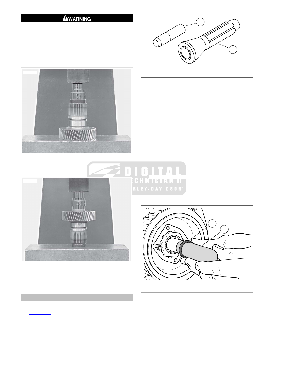
Figure 7-41. Pressing in Seal

sm02302

Figure 7-42. Installing Transmission Side Needle Bearing

in Main Driver Gear

MAINSHAFT SEAL REPLACEMENT

TOOL NAME

PART NUMBER

MAIN DRIVE GEAR SEAL INSTALLER

HD-47933

See 

Figure 7-43

. If the mainshaft seal was not installed with

the main drive gear needle bearings (or if a faulty seal is dis-
covered with the main drive gear installed in the transmission
case), the seal can be installed using the MAIN DRIVE GEAR
SEAL INSTALLER (Part No. HD-47933).

1

2

sm03045

1.

Driver

2.

Seal protector sleeve

Figure 7-43. Main Drive Gear Seal Installer (Part No.

HD-47933)

1.

Remove the damaged seal using a seal remover or rolling
head pry bar.

2.

Inspect bore to be sure it is clean and smooth.

3.

See 

Figure 7-44

. Place the seal protector sleeve (1) over

the end of the mainshaft. Lightly lubricate the protector
sleeve and seal ID with clean transmission oil.

4.

Verify that the garter spring is in place on the lip of the
new oil seal. Apply a light coat of H-D 20W-50 engine oil
to the seal lip.

5.

Squarely seat the mainshaft seal (2) on the seal protector
sleeve with the garter spring facing the bearing.

6.

See 

Figure 7-45

. Using MAIN DRIVE GEAR SEAL

INSTALLER (Part No. HD-47933), hand press seal onto
mainshaft and into end of main drive gear. A rubber mallet
may be used to lightly tap driver, if necessary. Seal is
properly installed when seal driver contacts end of main
drive gear.

2

1

sm03048

1.

Seal protector sleeve

2.

Seal

Figure 7-44. Seal Protector Sleeve

7-22  2008 Touring Service: Transmission

sm03049

Figure 7-45. Seal Driver

INSTALLATION

TOOL NAME

PART NUMBER

INSTALLER CUP

HD-35316-12

CROSS PLATE

HD-35316-3A

8 IN. BOLT

HD-35316-4A

12 IN. BOLT

HD-35316-5

WASHER

HD-35316-7

BEARING DRIVER

HD-35316-8

INSTALLER

HD-47856-1

PILOT

HD-47856-2

ADAPTER

HD-47856-3

NUT

HD-47856-6

CROW'S FOOT WRENCH

HD-47856-7

Improper tightening of sprocket nut can cause drive
component damage. (00541b)

Installing Main Drive Gear Bearing

NOTE

CROSS PLATE (Part No. HD-35316-3A) will retrofit to earlier
transmissions. Note that one end of cross plate is stamped,
"UP 6 SPEED". Mount cross plate with this end pointing up for
6 speed transmissions.

1.

See 

Figure 7-46

. Place CROSS PLATE (Part No. HD-

35316-3A) (2) on right side of transmission case as shown,
and secure with two screws (3). Position cross plate so
that large bolt hole in cross plate is lined up with center of
main drive gear bearing bore in left side of transmission
case.

2.

Apply a light coat of graphite lubricant to the threads of 12
IN. BOLT (Part No. HD-35316-5) (1) and install through
cross plate and main drive gear bearing bore.

3.

At left side of case, place main drive gear bearing (4),
BEARING DRIVER (Part No. HD-35316-8) (5), NICE
BEARING (6), FLAT WASHER (7) and NUT (8) over end
of bolt.

4.

Tighten nut until main drive gear bearing bottoms against
lip cast into transmission case bearing bore.

1

2

8

7

4

3

6

5

sm03051

1.

12 in. bolt

2.

Cross plate

3.

Screw (2)

4.

Main drive gear bearing

5.

Bearing driver

6.

Nice bearing

7.

Flat washer

8.

Nut

Figure 7-46. Installing Main Drive Gear Bearing (Typical)

Installing Main Drive Gear

NOTE

See 

Figure 7-47

. Make sure new o-ring (4) is installed onto

main drive gear (3). Lubricate o-ring with clean engine oil before
installing drive gear into transmission case.

1.

See 

Figure 7-47

. Apply a light coat of graphite lubricant

to the threads of 8 IN. BOLT (Part No. HD-35316-4A) (1)
and insert through WASHER (Part No. HD-35316-7) (2)
and main drive gear (3). Insert assembly into transmission
case, through main drive gear bearing.

2.

At outside of case, place INSTALLER CUP (Part No. HD-
35316-12) (5), NICE BEARING (6), FLAT WASHER (7)
and NUT (8) over end of bolt.

3.

Tighten nut until main drive gear contacts main drive gear
bearing.

NOTE

See 

Figure 7-48

. In next step, bearing retaining ring must be

installed with the flat side facing the bearing and the opening
in the ninety degree range shown.

2008 Touring Service: Transmission  7-23

Wear safety glasses or goggles when removing or
installing retaining rings. Retaining rings can slip from the
pliers and could be propelled with enough force to cause
serious eye injury. (00312a)

4.

See 

Figure 7-49

. Install new retaining ring (2).

6

7

8

5

4

2

1

3

sm03052

1.

8 in. bolt

2.

Washer

3.

Main drive gear

4.

O-ring

5.

Installer cup

6.

Nice bearing

7.

Flat washer

8.

Nut

Figure 7-47. Installing Main Drive Gear (Typical)

sm03053

Figure 7-48. Retaining Ring Opening

Installing Main Drive Gear Large Seal

1.

See 

Figure 7-49

. From outside of crankcase, install

PILOT (Part No. HD-47856-2) over end of main drive gear
bearing inner race.

2.

Coat lips of new main drive gear seal with FORMULA+
TRANSMISSION AND PRIMARY CHAINCASE LUB-
RICANT (Part No. 99851-05, qt).

3.

See 

Figure 7-50

. Place seal over pilot with garter spring

facing bearing, and position seal squarely in end of
crankcase bore.

NOTE

ADAPTER (Part No. HD-47856-3) and main drive gear have
right-hand threads.

4.

See 

Figure 7-51

. Thread ADAPTER (Part No. HD-47856-

3) onto end of main drive gear until it contacts main drive
gear.

1

2

sm03057

1.

Pilot

2.

Retaining Ring

Figure 7-49. Install Pilot

sm03058

Figure 7-50. Place Main Drive Gear Seal Over Pilot

7-24  2008 Touring Service: Transmission

sm03059

Figure 7-51. Install Adapter

5.

See 

Figure 7-52

. Slide INSTALLER (Part No. HD-47856-

1) (1) over adapter until cupped end of installer is flat
against seal.

6.

Thread NUT (Part No. HD-47856-6) (2) onto end of
adapter, until it tightens against installer.

7.

See 

Figure 7-53

. Place CROW'S FOOT WRENCH (Part

No. HD-47856-7) (1) with 1/2 inch drive breaker bar (2)
on large nut. Place an adjustable wrench (3) on flats of
hex head cast into end of adapter.

8.

Holding adjustable wrench, tighten large nut with crow's
foot wrench until outer face of seal is flush with outer edge
of transmission bore.

NOTE

It is acceptable to recess seal as much as  0.030 in. (0.762
mm) below outer edge of bore. Seal depth will be controlled
by tool.

9.

Remove nut, installer, adapter and pilot.

10. Install side door and transmission components. See

7.5 TRANSMISSION ASSEMBLY, Installation

.

11. Install sprocket and drive belt. See 

6.6 TRANSMISSION

SPROCKET

. Do not adjust belt at this time.

12. Install the bearing inner race on the transmission main-

shaft. See 

7.5 TRANSMISSION ASSEMBLY, Assembly

.

13. Install the primary chaincase housing. See 

6.4 PRIMARY

CHAINCASE HOUSING, Installation

.

14. Install the clutch assembly, primary chain, chain tensioner

assembly and compensating sprocket components See

6.3 DRIVE COMPONENTS, Installation

.

15. Install the primary chaincase cover. See 

6.2 PRIMARY

CHAINCASE COVER, Installation

.

16. Adjust the drive belt. See 

1.13 REAR BELT DEFLECTION,

Setting Belt Deflection

.

17. Install exhaust system. See 

4.18 EXHAUST SYSTEM,

Installation

.

1

2

sm03061

1.

Installer

2.

Nut

Figure 7-52. Installer and Nut

1

3

2

sm03062

1.

Crow's foot wrench

2.

1/2 inch breaker bar

3.

Adjustable wrench

Figure 7-53. Press Seal Into Crankcase

2008 Touring Service: Transmission  7-25

7.7

TRANSMISSION CASE

REMOVAL

Disconnect negative (-) battery cable first. If positive (+)
cable should contact ground with negative (-) cable con-
nected, the resulting sparks can cause a battery explosion,
which could result in death or serious injury. (00049a)

1.

Disconnect battery, negative (-) cable first.

2.

Drain engine oil. See 

1.5 ENGINE OIL AND FILTER,

Changing Oil and Oil Filter: Touring Models

.

3.

Drain transmission lubricant. See 

1.10 TRANSMISSION

LUBRICANT, Transmission Lubrication: Touring Models

.

4.

Remove starter. See 

5.2 STARTER, Removal

.

5.

Remove transmission assembly. See 

7.5 TRANSMISSION

ASSEMBLY, Removal

.

6.

Remove oil pan. See 

3.29 OIL PAN

.

7.

Position jack under lower frame crossmember to support
rear of motorcycle. Slide wooden blocks beneath the
crankcase to support the weight of the engine and trans-
mission assembly.

8.

Remove rear fork. See 

2.22 REAR FORK, Removal

.

9.

Disconnect vehicle speed sensor (VSS). See

8.22 VEHICLE SPEED SENSOR (VSS), VSS

.

10. Disconnect neutral switch. See 

8.23 NEUTRAL SWITCH,

Removal

.

11. Remove fastener from ground post at top of transmission

case and remove battery negative ring terminal.

12. Move O2 sensor, starter solenoid, neutral switch and VSS

harness out of the way.

13. Mark splines on shift arm and shift shaft to assist in

assembly. Remove shift arm from shift shaft.

14. In a crosswise pattern, remove four fasteners that connect

transmission to engine.

NOTE

See 

Figure 7-54

. Do not use a hammer to remove transmission.

If the transmission sticks or binds on the ring dowels, gently
pry away from crankcase using the indent.

15. Move transmission rearward until two ring dowels in lower

flange are free of crankcase. Remove transmission case
from left side of the motorcycle.

sm03566

Figure 7-54. Transmission Case Pry Point

INSTALLATION

1.

Install new ground post at top of transmission case.
Tighten ground post until snug.

NOTE

 new transmission case comes with the shifter shaft sleeve
and seal, centering screw, countershaft needle bearing and
main drive gear bearing and seal installed.

2.

Thoroughly wipe all engine oil from pockets in crankcase
flange.

3.

Install new engine-to-transmission gasket engaging two
index pins in holes of transmission flange.

4.

Verify that transmission dowels are seated. Place trans-
mission case into position behind crankcase. Mate engine
and transmission flanges.

5.

Install and tighten fasteners.

a.

Shorter bolts are installed at the top, longer fasteners
are installed at the bottom. Using a crosswise pattern,
hand tighten fasteners.

b.

See 

Figure 7-55

Tighten bolts in the sequence shown

to 15 ft-lbs (20.3 Nm) in the same crosswise pattern.

c.

Final tighten bolts to 30-35 ft-lbs (40.7-47.5 Nm).

6.

Install oil pan. See 

3.29 OIL PAN

7.

Install rear fork. See 

2.22 REAR FORK, Installation

.

8.

Install shift arm on shift shaft. Align marks made during
disassembly.

9.

Install transmission and side door assembly. See

7.5 TRANSMISSION ASSEMBLY, Installation

.

10. Connect battery ground (-) cable to ground post at top of

transmission case. Tighten securely.

11. Adjust drive belt tension.

1.13 REAR BELT DEFLECTION

.

12. Verify vehicle alignment.

2.11 VEHICLE ALIGNMENT

.

13. Install primary chaincase.

6.4 PRIMARY CHAINCASE

HOUSING

.

7-26  2008 Touring Service: Transmission

14. Install drive components. See 

6.3 DRIVE COMPONENTS

.

NOTE

The gasket between the primary chaincase cover and chain-
case must be replaced each time the cover is removed. Failure
to replace this gasket may cause primary chaincase leaks.

15. Install primary chaincase cover.

6.2 PRIMARY CHAIN-

CASE COVER

.

16. Install neutral switch and tighten to 120-180 in-lbs (13.6-

20.3 Nm).

17. Install VSS and tighten screw to 84-132 in-lbs (9.5-14.9

Nm)

18. Mate VSS, O2 sensors, starter solenoid and neutral switch

connectors to main harness.

19. Install the exhaust system.

4.18 EXHAUST SYSTEM

.

20. Clean transmission drain plug and install. Tighten to 14-

21 ft-lbs (19.0-28.5 Nm). Place motorcycle in an upright
position. Fill transmission to proper level with fresh trans-
mission fluid. See 

1.10 TRANSMISSION LUBRICANT

.

Do not overfill the primary chaincase with lubricant.
Overfilling can cause rough clutch engagement, incom-
plete disengagement, clutch drag and/or difficulty in
finding neutral at engine idle. (00199b)

21. Fill primary.

1.9 PRIMARY CHAIN, Chaincase Lubricant:

Touring Models

.

22. Fill engine oil.

1.5 ENGINE OIL AND FILTER, Changing

Oil and Oil Filter: Touring Models

.

Connect positive (+) battery cable first. If positive (+) cable
should contact ground with negative (-) cable connected,
the resulting sparks can cause a battery explosion, which
could result in death or serious injury. (00068a)

23. Connect battery cables.

4

2

1

3

sm02180

Figure 7-55. Transmission Housing to Crankcase Torque

Sequence

DISASSEMBLY

Shifter Arm Assembly

1.

See 

Figure 7-56

. After removing door assembly, remove

screw (8) and shifter rod lever (9) from the shifter pawl
lever assembly (1).

2.

Remove retaining ring (7), washer (6) and seal (5). Discard
retaining ring and seal. Pull shifter pawl lever assembly
out of the transmission case.

3.

Inspect sleeve (2) inside transmission case.

CLEANING AND INSPECTION

Compressed air can pierce the skin and flying debris from
compressed air could cause serious eye injury. Wear
safety glasses when working with compressed air. Never
use your hand to check for air leaks or to determine air
flow rates. (00061a)

1.

Clean all parts in solvent except the case and main drive
gear needle bearings. Blow parts dry with low pressure
compressed air.

NOTE

Never wash the transmission case and needle bearings with
solvent unless the needle bearings are to be replaced. Normal
cleaning methods will wash dirt or other contaminants into the
bearing case (behind the needles) and leads to bearing failure.

2.

See 

Figure 7-56

. Inspect the shifter pawl lever assembly

(1) for wear. Replace assembly if pawl ends are damaged.
Replace centering spring (3) if elongated.

3.

Inspect the shifter spring (4). Replace if the spring fails to
hold the pawl on the cam pins.

2008 Touring Service: Transmission  7-27

4.

Thoroughly clean the oil pan with solvent.

5.

Inspect preformed transmission top cover vent hose for
nicks, cuts or general deterioration. Replace as necessary.
Use low-pressure compressed air to verify that hose and
fitting are unobstructed.

4

1

2

3

5

7

8

11

9

6

10

sm03066

1.

Shifter pawl lever assembly

2.

Sleeve (inside transmission case)

3.

Shift lever centering spring

4.

Shifter shaft lever spring

5.

Seal

6.

Washer

7.

Retaining ring

8.

Screw

9.

Shifter rod lever

10. Washer
11. Screw

Figure 7-56. Shifter Arm Assembly

ASSEMBLY

Countershaft Needle Bearing Replacement

1.

Find a suitable bearing driver  1.25 in. (31.75 mm) in dia-
meter.

2.

From the outside of the transmission case place the needle
bearing open end first next to the bearing bore. Hold the
driver squarely against the closed end of the bearing and
tap the bearing into place. The bearing is properly posi-
tioned when it is driven inward flush with the outside sur-
face of the case or to a maximum depth of  0.030 in. (0.76
mm).

3.

Lubricate the bearing with transmission lubricant.

Shifter Pawl Lever Assembly

1.

See 

Figure 7-56

Verify that sleeve (2) is inside transmis-

sion case.

2.

See 

Figure 7-57

. Slide shifter lever centering spring (3)

over shaft of shifter pawl lever assembly (2). Align opening
on spring with tab on lever.

3.

Place shifter shaft lever spring (4) on shifter pawl lever
assembly.

NOTE

Do not bend shifter shaft lever spring more than necessary for
assembly.

4.

See 

Figure 7-58

. Insert the assembly into the transmission

case.

5.

See 

Figure 7-59

. Verify that pin sits inside shifter shaft

lever spring.

6.

See 

Figure 7-58

. Install a new seal. Install washer (1) and

new retaining ring (2).

NOTE

In next step, shifter rod lever must be installed so angle of lever
is toward front of vehicle, one spline from vertical.

7.

See 

Figure 7-56

. Install shifter rod lever (9) on the shifter

pawl lever assembly shaft end using screw (8). Tighten
to 18-22 ft-lbs (24.4-29.8 Nm).

2

1

4

3

sm03067

1.

Pawl (part of shifter pawl lever assembly)

2.

Shifter pawl lever assembly

3.

Shifter lever centering spring

4.

Shifter shaft lever spring

Figure 7-57. Shifter Pawl Lever Assembly

4

2

1

3

sm03068

1.

Washer (with seal behind)

2.

Retaining ring

3.

Shifter shaft lever

4.

Pin

Figure 7-58. Shifter Shaft Lever, Exterior View

7-28  2008 Touring Service: Transmission

SUBJECT

............................................................................................................................

PAGE NO.

8.1 SPECIFICATIONS: ELECTRICAL.............................................................................................8-1
8.2 VOLTAGE REGULATOR............................................................................................................8-2
8.3 ELECTRONIC CONTROL MODULE (ECM).............................................................................8-3
8.4 IGNITION COIL.........................................................................................................................8-4
8.5 SYSTEM FUSES AND RELAYS...............................................................................................8-6
8.6 ELECTRICAL CADDIES...........................................................................................................8-8
8.7 SECURITY SIREN..................................................................................................................8-15
8.8 BATTERY.................................................................................................................................8-16
8.9 HEADLAMP: ALL EXCEPT FLTR............................................................................................8-18
8.10 HEADLAMP: FLTR................................................................................................................8-20
8.11 AUXILIARY LAMPS AND BRACKETS..................................................................................8-22
8.12 TAIL LAMP.............................................................................................................................8-27
8.13 FENDER TIP LAMPS............................................................................................................8-31
8.14 TURN SIGNAL LAMPS.........................................................................................................8-36
8.15 LICENSE PLATE LAMPS AND BRACKET: FLHX.................................................................8-43
8.16 TSM/HFSM............................................................................................................................8-45
8.17 IGNITION/LIGHT KEY SWITCH AND FORK LOCK.............................................................8-47
8.18 FAIRING CAP SWITCHES: FLHTC/U...................................................................................8-52
8.19 INSTRUMENT NACELLE SWITCHES: FLTR.......................................................................8-54
8.20 CRANKSHAFT POSITION SENSOR (CKP).........................................................................8-58
8.21 ALTERNATOR.......................................................................................................................8-59
8.22 VEHICLE SPEED SENSOR (VSS).......................................................................................8-61
8.23 NEUTRAL SWITCH...............................................................................................................8-62
8.24 OIL PRESSURE SWITCH AND SENDER............................................................................8-63
8.25 STOPLIGHT SWITCHES......................................................................................................8-64
8.26 HORN....................................................................................................................................8-65
8.27 CIGARETTE LIGHTER: FLHX, FLHT/C/U, FLTR..................................................................8-66
8.28 GAUGES AND INSTRUMENTS: FLHX, FLHT/C/U, FLTR....................................................8-67
8.29 INDICATOR LAMPS: FLHX, FLHT/C/U, FLTR.......................................................................8-69
8.30 GAUGES AND INSTRUMENTS: FLHR/C.............................................................................8-70
8.31 INDICATOR LAMPS: FLHR/C...............................................................................................8-72
8.32 ADVANCED AUDIO SYSTEM...............................................................................................8-73
8.33 WIRE TROUGH.....................................................................................................................8-79
8.34 MAIN WIRING HARNESS.....................................................................................................8-82
8.35 INTERCONNECT HARNESS................................................................................................8-94
8.36 RADIO ANTENNA CABLE..................................................................................................8-103
8.37 AUDIO HARNESS: FLHTCU...............................................................................................8-107
8.38 CB ANTENNA CABLE: FLHTCU.........................................................................................8-109
8.39 HANDLEBAR SWITCH ASSEMBLIES................................................................................8-111

ELECTRICAL

8.1

SPECIFICATIONS: ELECTRICAL

SPECIFICATIONS

Table 8-1. Ignition

DATA

IGNITION

1000 ± 50 RPM

Idle speed

12 mm

Spark plug size

0.038-0.043 in.

Spark plug gap

0.97-1.09 mm

Harley-Davidson

No. 6R12

(no substitute)

Spark plug type

0.5-0.7 ohms

Ignition coil primary resistance

5500-7500 ohms

Ignition coil secondary resistance

Table 8-2. Fuses

AMPS

FUSE

40

Maxi-fuse

15

Brakes

15

Accessory

15

P&A

15

Radio power/siren

15

ECM power

15

Ignition

15

Engine control: active exhaust (HDI only)

15

Lighting

15

Instruments

15

Headlamp

30

ABS

15

P&A ignition

15

Fuel pump

15

Battery

15

Radio memory

Table 8-3. Charging System

DATA

CHARGING SYSTEM

19 amp hour/270 CCA

Battery

16-23 VAC per 1000 RPM

Alternator AC voltage output

0.1-0.2 ohms

Alternator stator coil resistance

14.3-14.7

@

75° F (24° C)

Regulator voltage output @ 3600
RPM

35-50 amps

Regulator amperes @ 3000 RPM

2008 Touring Service:  Electrical  8-1

8.2

VOLTAGE REGULATOR

REMOVAL

1.

Remove maxi-fuse. See 

8.5 SYSTEM FUSES AND

RELAYS

.

2.

Remove locknuts from studs on lower frame crossmember.
Lift voltage regulator off studs.

3.

Release conduit from P-clips under left and right side legs
of voltage regulator. Allow voltage regulator to hang upside
down at front of lower frame crossmember. See 

Figure 8-2

.

4.

Pull away locking latch and remove socket of voltage
regulator connector [77], 2-place Lyall, at bottom right side
of voltage regulator.

5.

Pull away locking latch and remove socket of stator con-
nector [46], 3-place Lyall, at bottom left side of voltage
regulator.

NOTE

The rubber molded voltage regulator and stator connectors
are not serviceable. Damage to terminals, molding or locking
latches requires voltage regulator and/or stator replacement.

6.

Remove voltage regulator from motorcycle.

INSTALLATION

1.

Position voltage regulator upside down at front of lower
frame crossmember. See 

Figure 8-2

.

2.

Install socket of stator connector [46], 3-place Lyall, at
bottom left side of voltage regulator. Push against locking
latch until socket is fully engaged.

3.

Install socket of voltage regulator connector [77], 2-place
Lyall, at bottom right side of voltage regulator. Push
against locking latch until socket is fully engaged.

4.

Turning voltage regulator right side up, start onto studs
on lower frame crossmember.

5.

Capture stator connector conduit in left side P-clip. Capture
voltage regulator connector conduit in right side P-clip.
See 

Figure 8-1

. Remove slack to ensure that stator conduit

does not contact front engine stabilizer link.

6.

Install locknuts on studs and alternately tighten to 70-100
in-lbs (7.9-11.3 Nm).

7.

Install maxi-fuse. See 

8.5 SYSTEM FUSES AND RELAYS

.

8.

Load test charging system.

1

2

sm03470

1.

Voltage regulator [77]

2.

Stator [46]

Figure 8-1. Voltage Regulator (Left Side View)

2

3

1

sm03471

1.

Stator [46A]

2.

Voltage regulator [77A]

3.

Locking latch

Figure 8-2. Voltage Regulator (Bottom View)

8-2  2008 Touring Service:  Electrical

8.3

ELECTRONIC CONTROL MODULE (ECM)

ECM

Removal

1.

Remove seat. See 

2.26 SEAT

.

2.

Pushing rear catch away, lift up ECM until free of top
caddy.

3.

Disconnect ECM connector [78] as follows:

a.

While depressing button on socket housing, rotate
locking bar until seated in the rearward position (index
pin on locking bar engages rear notch in socket
housing).

NOTE

Internal latches are not fully disengaged until locking bar
is seated in the rearward position. Forcing socket housing
with latches partially engaged will result in connector
damage.

b.

Gently pully apart pin and socket housings.

Installation

1.

Connect ECM connector [78] as follows:

a.

Verify that locking bar is seated in the rearward posi-
tion (index pin on locking bar engages rear notch in
socket housing).

b.

Aligning large ground pin (73) with blue socket, mate
pin and socket housings.

NOTE

If pin and socket housings are not properly aligned during
the installation attempt, damage to large ground pin (73)
will likely occur. Damage to pin requires ECM replacement.

c.

Rotate locking bar until seated in the forward position
(index pin on locking bar engages front notch in
socket housing).

NOTE

Pin and socket housings must be fully engaged before
locking bar is rotated to the forward position. Forcing
locking bar without full engagement will result in connector
damage.

2.

Place ECM in approximate position on top caddy (oriented
to the right of the left side stop and rear of the front catch).

3.

Push ECM forward until front catch engages, and then
push down on rear of ECM to engage rear catch.

4.

Slide ECM toward left side stop until holes engage two
index pins on right side of top caddy.

5.

Install seat. See 

2.26 SEAT

.

2008 Touring Service:  Electrical  8-3

8.4

IGNITION COIL

REMOVAL

1.

Remove fuel tank. See 

4.4 FUEL TANK

.

2.

Unplug spark plug cables from ignition coil towers.

3.

See 

Figure 8-3

. Remove ignition coil connector [83].

4.

Pull sides of ignition coil bracket outward to remove from
bosses of front fuel tank mount.

5.

Remove two screws to free ignition coil from bracket.

INSTALLATION

1.

See 

Figure 8-4

. Align holes in new ignition coil with holes

in bracket. Install two screws and alternately tighten to 84-
144 in-lbs (9.5-16.3 Nm).

2.

See 

Figure 8-3

With the coil towers facing rear, hold

ignition coil and bracket at bottom of frame backbone. Pull
sides of bracket outward and install on bosses of front fuel
tank mount.

3.

Install ignition coil connector [83].

4.

See 

Figure 8-5

. Install spark plug cable to front cylinder

onto left side coil tower. Verify that spark plug cable is
captured in double-sided cable clip at bottom left side of
frame backbone. Install new cable clip on T-stud if dam-
aged or missing.

5.

Install spark plug cable to rear cylinder onto right side coil
tower. Verify that spark plug cable is captured in two
single-sided cable clips at bottom left side of frame back-
bone. Install new cable clips on T-studs if damaged or
missing.

6.

Install fuel tank. See 

4.4 FUEL TANK

.

sm03511

Figure 8-3. Remove Ignition Coil Bracket From Vehicle

2

1

sm03467

1.

To front cylinder

2.

To rear cylinder

Figure 8-4. Install Bracket to Ignition Coil

8-4  2008 Touring Service:  Electrical

6

3

5

2

4

1

sm05131

4.

1.

Right side ignition coil tower

Left side ignition coil tower

2.

5.

Double-sided clip

Single-sided clip (2)

6.

3.

Rear cylinder

Front cylinder

Figure 8-5. Spark Plug Cable Routing (Bottom Left Side View)

2008 Touring Service:  Electrical  8-5

8.5

SYSTEM FUSES AND RELAYS

MAXI-FUSE

Removal

1.

Remove left side saddlebag. See 

2.27 SADDLEBAGS

.

2.

Remove left side cover.

3.

Pull maxi-fuse from maxi-fuse holder. See 

Figure 8-6

.

Installation

1.

Insert maxi-fuse into maxi-fuse holder. See 

Figure 8-6

.

2.

Install left side cover.

3.

Install left side saddlebag. See 

2.27 SADDLEBAGS

.

MAXI-FUSE HOLDER

Removal

1.

Remove left side saddlebag. See 

2.27 SADDLEBAGS

.

2.

Remove left side cover.

3.

Pull maxi-fuse from maxi-fuse holder.

4.

Remove battery. See 

1.16 BATTERY MAINTENANCE

.

5.

Inboard of left side caddy:

a.

Cut front cable strap to release main harness bundle
and main power cable (to maxi-fuse holder). Remove
and discard cable strap.

b.

Push up on tongue at bottom of harness cover to
release from slot in caddy, and then rotate up and
disengage hinges.

c.

Depress latches on maxi-fuse holder and pull from
hole in caddy.

NOTE

If further disassembly of the left side caddy is necessary, see

8.6 ELECTRICAL CADDIES

.

6.

Remove socket terminals from maxi-fuse holder. See

A.5 DELPHI MAXI FUSE HOUSING

.

Installation

1.

Install socket terminals into maxi-fuse holder. See

A.5 DELPHI MAXI FUSE HOUSING

.

2.

Inboard of left side caddy:

a.

Push maxi-fuse holder into hole until it locks in place.

b.

Install new cable strap through front slot in caddy
capturing main harness bundle and main power cable
(to maxi-fuse holder).

c.

Engage hinges and rotate harness cover down over
main harness bundle. Push up on tongue at bottom
of cover to engage slot in caddy.

NOTE

If further assembly of the left side caddy is necessary, see

8.6 ELECTRICAL CADDIES

.

3.

Install battery. See 

1.16 BATTERY MAINTENANCE

.

4.

Insert maxi-fuse into maxi-fuse holder.

5.

Install left side cover.

6.

Install left side saddlebag. See 

2.27 SADDLEBAGS

.

SYSTEM FUSES AND RELAYS

Removal

1.

Remove left side saddlebag. See 

2.27 SADDLEBAGS

.

2.

Remove left side cover.

3.

Pull maxi-fuse from maxi-fuse holder.

4.

Push up on tongue at bottom of fuse block cover to release
from slot in caddy, and then rotate up and disengage
hinge.

5.

Remove system fuse/relay from fuse block. Replace fuse
if the element is burned or broken. Automotive type ATO
fuses are used. See 

Figure 8-6

.

Installation

1.

Install system fuse/relay in fuse block. See 

Figure 8-6

.

2.

Engage hinge and rotate fuse block cover down over fuse
blocks. Push up on tongue at bottom of cover to engage
slot in caddy.

3.

Insert maxi-fuse into maxi-fuse holder.

4.

Install left side cover.

5.

Install left side saddlebag. See 

2.27 SADDLEBAGS

.

8-6  2008 Touring Service:  Electrical

A

2

19

18

21

9

1

10

13

12

11

16

15

14

7

8

17

4

5

6

3

20

sm05087

12.

1.

Lighting

Maxi-fuse

2.

13.

Brakes

Instruments

14.

3.

Headlamp

Accessory

4.

15.

P&A

ABS (if provided)

16.

5.

Brake light relay

Radio/siren (if provided)

6.

17.

ECM power

P&A ignition (if provided)

18.

7.

EFI system relay

Starter relay

8.

19.

Ignition

Fuel pump

20.

9.

Battery

Engine control (HDI only)

10.

21.

Spare

Radio memory (if provided)

11. Spare

Figure 8-6. Fuse Blocks

FUSE BLOCKS

Removal

1.

Remove left side caddy as necessary to release fuse
blocks. See 

8.6 ELECTRICAL CADDIES

.

2.

Remove system fuses and relays from fuse blocks.

3.

Remove socket terminals from fuse blocks. See

A.12 PACKARD 280 METRI-PACK RELAY AND FUSE
BLOCK CONNECTORS

.

Installation

1.

Install socket terminals into fuse blocks. See

A.12 PACKARD 280 METRI-PACK RELAY AND FUSE
BLOCK CONNECTORS

.

2.

Install system fuses and relays into fuse blocks. See

Figure 8-6

.

3.

Install fuse blocks into left side caddy. Install left side
caddy. See 

8.6 ELECTRICAL CADDIES

.

2008 Touring Service:  Electrical  8-7

8.6

ELECTRICAL CADDIES

GENERAL

The battery tray and the left and right side caddies consist of
three interlocking segments. While the left and right side cad-
dies can be removed separately, both caddies must be
removed to extract the battery tray. See 

Figure 8-7

.

2

1

3

4

sm04215

1.

Top caddy

2.

Left side caddy

3.

Battery tray

4.

Right side caddy

Figure 8-7. Battery Tray With Interlocking Caddies (Top

View)

TOP CADDY

Removal

1.

Remove seat. See 

2.26 SEAT

.

2.

If present, release groove on HFSM antenna from tongue
at front of caddy. Move connector and conduit out of the
way. See 

Figure 8-8

.

3.

Pushing rear catch away, lift up ECM until free of caddy.

4.

Remove screw to release clamp on caddy from frame
crossmember.

5.

Remove caddy from motorcycle.

Installation

1.

With the clamp at the rear, install caddy above battery.

2.

Install screw to fasten clamp on caddy to frame cross-
member. Tighten screw to 15-20 ft-lbs  (20-27 Nm).

6

4

2

5

3

5

1

sm04435

1.

Tongue

2.

Rear catch

3.

Front catch

4.

Left side stop

5.

Index pin

6.

Clamp

Figure 8-8. Top Caddy

3.

Place ECM in approximate position on caddy (oriented to
the right of the left side stop and rear of the front catch).

4.

Push ECM forward until front catch engages, and then
push down on rear of ECM to engage rear catch.

5.

Slide ECM toward left side stop until holes engage two
index pins on right side of caddy.

6.

Routing conduit along inboard side of left upper frame
tube, engage groove on HFSM antenna on tongue at front
of caddy, if present.

7.

Install seat. See 

2.26 SEAT

.

LEFT SIDE CADDY

Removal

1.

Remove left side saddlebag. See 

2.27 SADDLEBAGS

.

2.

Remove left side cover.

3.

Remove battery. See 

1.16 BATTERY MAINTENANCE

.

4.

Remove front screw to release caddy from battery tray.
Remove rear screw to release caddy from frame weldment.

5.

Disconnect socket housing from siren, if equipped, and
then push two retaining latches forward and pull siren from
compartment in caddy.

6.

Cut front cable strap to release main harness bundle and
main power cable (to maxi-fuse holder) from inboard side
of caddy. Remove and discard cable strap. See 

Figure 8-9

.

8-8  2008 Touring Service:  Electrical


Content      ..     23      24      25      26     ..