Harley Davidson 2008 Touring Models. Service Manual - page 26
 

  Главная      Harley Davidson     Harley Davidson 2008 Touring Models. Service Manual


Search            copyright infringement  


Content      ..     24      25      26      27     ..


Harley Davidson 2008 Touring Models. Service Manual - page 26


6

16

1

7

2

3

12

5

17

9

4

14

13

2

3

1

17

11

9

4

10

18

19

15

8

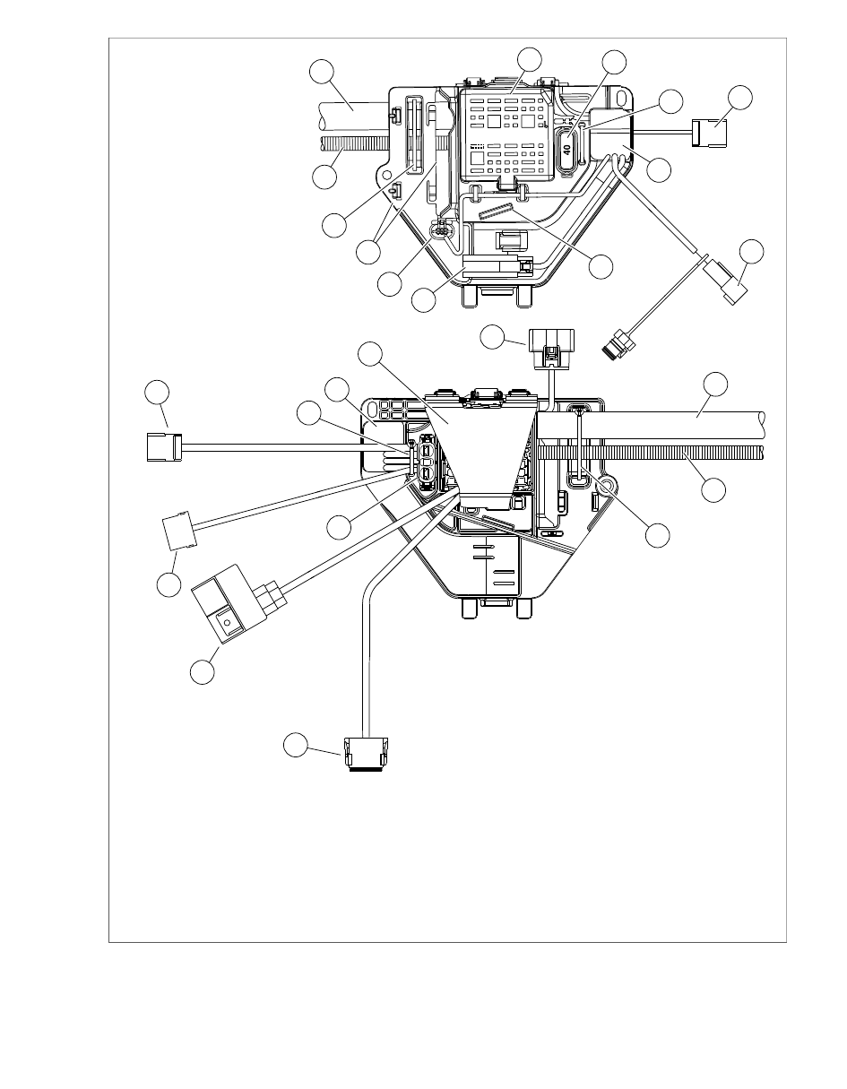
sm04387

11.

1.

Harness cover

Front cable strap

2.

12.

Main harness bundle

Harness cover tongue slot

13.

3.

Fuse block cover

Main power cable

4.

14.

Rear cable strap

Maxi-fuse

15.

5.

Maxi-fuse holder

Data link [91]

6.

16.

ABS diode pack [201]

Instrument console [20]

17.

7.

Rear fender lights harness [7]

P&A siren [142]

8.

18.

Siren compartment/retaining latches

Ignition keyswitch relay [126]

19.

9.

TSM/HFSM [30]

Square shaped opening

10. Ignition switch jumper harness [222]

Figure 8-9. Left Side Caddy (FLHR/C)

2008 Touring Service:  Electrical  8-9

2

1

sm04389

1.

Caddy tab/battery tray slot

2.

Ignition switch jumper harness connector
anchor hole (FLHR/C)

Figure 8-10. Disengage Left Side Caddy Tab From Battery

Tray Slot

7.

Cut rear cable strap to release data link, diode pack (ABS
only), siren, rear fender lights and ignition switch jumper
harness (FLHR/C) connector conduit from inboard side of
caddy. Remove and discard cable strap.

8.

Release tongue on data link connector from top groove
on caddy. If ABS equipped, release tongue on diode pack
connector from bottom groove. Feed conduit and con-
nectors through small square shaped opening to inboard
side of caddy.

9.

Disconnect siren socket housing from mock pin housing
on caddy if siren is not provided. Free conduit from hooks
and feed through square shaped opening to inboard side
of caddy.

10. On FLHR/C models, pull anchor on ignition switch jumper

harness connector, 4-place Packard, from hole in left side
of battery tray.

11. Loosen screw (with lifting strap) in middle finger of battery

tray.

12. While pulling up on battery tray, pull out caddy until tab is

free of slot on battery tray. See 

Figure 8-10

.

13. Pull up on caddy to unseat from weldment between frame

downtubes.

14. Remove harness cover from inboard side of caddy. Push

up on tongue at bottom of cover to release from slot in
caddy and then rotate up to disengage hinges.

15. Remove fuse block cover. Push up on tongue at bottom

of cover to release from slot in caddy and rotate up to
disengage hinge.

16. Push on bottom of fuse block to move inboard slightly,

and then lifting up on top center ear on caddy, push on
top of fuse block to remove.

17. Depress latches on maxi-fuse holder and pull from oblong

hole in caddy.

18. Remove caddy from motorcycle.

Installation

1.

Start bottom of fuse block into large square shaped
opening on inboard side of caddy, and then lifting up on
top center ear on caddy, start top of fuse block into
opening. Alternately work bottom and top of fuse block
into opening until it locks in place.

2.

Install fuse block cover. Engage hinge and rotate down
over fuse blocks. Push up on tongue at bottom of cover
to engage slot in caddy.

3.

From inboard side of caddy, push maxi-fuse holder into
oblong hole until it locks in place.

4.

Feed data link, diode pack (ABS only) and siren con-
nectors and conduit through small square shaped opening
to outboard side of caddy.

5.

Loosely install new cable strap through front slot in caddy
capturing main harness bundle and main power cable (to
maxi-fuse holder) on inboard side.

6.

Loosely install new cable strap through rear slot in caddy
capturing data link, diode pack (ABS only), siren, rear
fender lights and ignition switch jumper harness (FLHR/C)
connector conduit on inboard side.

7.

Install harness cover on inboard side of caddy. Engage
hinges and rotate down over main harness bundle. Be
sure to capture both the ignition keyswitch relay and
TSM/HFSM connector conduit. Push up on tongue at
bottom of cover to engage slot in caddy.

8.

Seat caddy on weldment between frame downtubes.

9.

While pulling up on battery tray, push on caddy until tab
engages slot on battery tray.

10. Engage tongue on data link connector in top groove on

caddy. If ABS equipped, engage tongue on diode pack
connector in bottom groove.

11. Start front screw to fasten caddy to battery tray. Start rear

screw to fasten caddy to frame weldment. Alternately
tighten screws to 72-96 in-lbs (8.1-10.9 Nm).

12. Tighten screw (with lifting strap) in middle finger of battery

tray to 72-96 in-lbs (8.1-10.9 Nm).

13. Tighten front and rear cable straps in slots of caddy. Cut

any excess cable strap material.

14. If equipped with siren, push two retaining latches forward

and slide siren into compartment in caddy. Connect siren
socket housing to siren (or mock pin housing on caddy if
siren is not provided). Engage conduit in hooks on caddy.

15. On FLHR/C models, install anchor on ignition switch

jumper harness connector, 4-place Packard, into hole in
left side of battery tray.

16. Install battery. See 

1.16 BATTERY MAINTENANCE

.

17. Install left side cover.

18. Install left side saddlebag. See 

2.27 SADDLEBAGS

.

8-10  2008 Touring Service:  Electrical

RIGHT SIDE CADDY

Removal

NOTE

The right side caddy is only present on motorcycles equipped
with ABS and/or active exhaust. If equipped with both ABS and
active exhaust, follow all steps provided. If ABS equipped only,
see steps 1-2 and 8-12. If only equipped with active exhaust,
see steps 1-7 and 10-13.

1.

Remove right side saddlebag. See 

2.27 SADDLEBAGS

.

2.

Remove right side cover.

3.

Remove cable clip from slotted flange at front of active
exhaust valve (just forward of the right side muffler).

4.

Push cam rearward to remove tension from actuator cable,
and then release ball end from slot.

5.

Release actuator cable from J-clamp fastened to rear
swingarm bracket.

6.

Pull anchored cable strap from hole in middle frame
downtube (adjacent to rear swingarm bracket) to release
main harness conduit. Push main harness conduit forward
to create clearance for actuator cable.

7.

Disconnect active exhaust valve actuator connector [179],
5-place Amp (Tyco).

8.

Remove three screws to release ABS module from caddy.
See 

Figure 8-11

.

2

3

1

5

6

4

sm04026

1.

Right side caddy

2.

Socket head screw (2)

3.

ABS module

4.

Socket head screw (3)

5.

Bushing (6)

6.

Rubber mount (3)

Figure 8-11. Right Side Caddy (ABS Equipped)

sm04217

Figure 8-12. Right Side Caddy Support Arm Lip

9.

Pull anchor on rear wheel speed sensor connector [168],
2-place Amp (Tyco), from hole at rear of caddy.

10. Remove front screw to release caddy from battery tray.

Remove rear screw to release support arms of battery tray
and caddy from frame weldment.

11. Pull caddy forward to release lip on support arm from

behind frame weldment (for side cover grommet). See

Figure 8-12

.

12. Holding ABS module in place (if equipped), pull caddy

outward to release saddles from frame downtubes.

13. If necessary, remove two screws (with flat washers) to

release active exhaust valve actuator from caddy.

Installation

NOTE

The right side caddy is only present on motorcycles equipped
with ABS and/or active exhaust. If equipped with both ABS and
active exhaust, follow all steps provided. If ABS equipped only,
see steps 3-6 and 12-13. If only equipped with active exhaust,
see steps 1-4 and 7-13.

1.

If removed, install two screws (with flat washers) to fasten
active exhaust valve actuator to caddy. Alternately tighten
screws to 32-40 in-lbs (3.6-4.5 Nm).

2.

Holding caddy, feed actuator cable inboard at rear of
middle frame downtube (staying rear of exhaust valve
actuator connector conduit), and then outboard again
between front of downtube and main harness conduit.

3.

Move caddy into position resting front and rear saddles
against frame downtubes and engaging lip on rear support
arm behind frame weldment (for side cover grommet).

4.

Start front screw to fasten caddy to battery tray. Start rear
screw to fasten support arms of battery tray and caddy to
frame weldment. If necessary, loosen screw in middle
finger of battery tray. Alternately tighten screws to 72-96
in-lbs (8.1-10.9 Nm).

5.

Install anchor on rear wheel speed sensor connector [168],
2-place Amp (Tyco), into hole at rear of caddy.

2008 Touring Service:  Electrical  8-11

6.

Start three screws to fasten ABS module to caddy.
Alternately tighten screws to 39-60 in-lbs (4.4-6.8 Nm).

7.

Connect active exhaust valve actuator connector [179],
5-place Amp (Tyco)

8.

Push cam rearward and install ball end of actuator cable
into slot of active exhaust valve (just forward of the right
side muffler). Verify that actuator cable is properly seated
in channel.

9.

Install cable clip onto slotted flange at front of active
exhaust valve.

10. Install actuator cable in J-clamp. Install hex screw to fasten

J-clamp to rear swingarm bracket, if removed, and tighten
to 35-45 in-lbs (4.0-5.1 Nm). Pinch J-clamp to ensure that
actuator cable remains captured.

11. Install anchored cable strap into hole in frame downtube

(inboard of rear swingarm bracket) to secure main harness
conduit.

12. Install right side cover.

13. Install right side saddlebag. See 

2.27 SADDLEBAGS

.

BATTERY TRAY

Removal

1.

Remove battery. See 

1.16 BATTERY MAINTENANCE

.

2.

Remove left side saddlebag. See 

2.27 SADDLEBAGS

.

3.

Remove left side cover.

4.

Remove front screw to release left side caddy from battery
tray. Remove rear screw to release caddy from frame
weldment.

5.

On FLHR/C models, pull anchor on ignition switch con-
nector, 4-place Packard, from hole in left side of battery
tray.

6.

Note the three fingers at the front of the battery tray.
Loosen screw (with lifting strap) to release middle finger
from frame crossmember. See 

Figure 8-13

.

7.

While pulling up on battery tray, pull out caddy until tab
on caddy is free of slot on battery tray. When free, pull up
on caddy to remove from weldment between frame
downtubes. See 

Figure 8-10

.

8.

Remove right side caddy. See 

8.6 ELECTRICAL CAD-

DIES, Right Side Caddy

.

NOTES

The right side caddy is only present on motorcycles
equipped with ABS and/or active exhaust. If neither is
provided, simply remove the right side saddlebag and side
cover, and then the screw and spacer to release support
arm of battery tray from frame weldment.

If active exhaust valve actuator is not provided, disconnect
unused socket housing from mock pin housing at side of
battery tray.

sm04216

Figure 8-13. Battery Tray Fingers (Rear View)

2

3

1

1

sm04218

1.

Brake line to rear brake caliper (ABS equipped)

2.

Fuel vapor vent/purge tubes (EVAP equipped)

3.

Active exhaust valve actuator mock pin housing
(used if not equipped)

Figure 8-14. Battery Tray Routing (Right Side View)

9.

Remove spring clip and pull TSM/HFSM module out of
opening on right side of frame crossmember. If present,
draw HFSM antenna and jumper harness below frame
crossmember thru empty slot of rubber boot on left side,
and then pull back up and out thru right side opening. Lay
jumper harness across rear fender.

10. Note the three fingers at the front of the battery tray.

Remove screw to release middle finger (with lifting strap)
from frame crossmember.

11. Pulling up on left finger, work main power cable (to maxi-

fuse holder) from inboard to outboard side.

12. Feed battery positive cable forward under frame cross-

member to area of starter.

8-12  2008 Touring Service:  Electrical

13. Remove flange nut from rear ground stud on left side of

frame backbone and remove chassis ground ring terminal.
Draw chassis ground ring terminal and battery negative
cable into battery tray and then feed forward under frame
crossmember to area of starter.

14. Work branches of main harness bundle in front of right

finger on battery tray.

15. On FLHX, FLHT/C/U and FLTR models, locate fuel over-

flow hose following rear of forward frame downtube to area
of oil pan. Pull fuel overflow hose up and out of the way.

16. If equipped, rotate ABS module outward releasing brake

line (to rear brake caliper) from channels at side of battery
tray. See 

Figure 8-14

.

17. On California models, proceed as follows:

a.

Disconnect fuel vapor vent tube (vapor valve to
charcoal canister) from front fitting stamped "TANK."

b.

Disconnect purge tube (charcoal canister to purge
solenoid) from rear fitting stamped "PURGE."

c.

Remove two screws (with flat washers) to release
charcoal canister from bottom of battery tray.

d.

Slide charcoal canister out opening on right side of
motorcycle.

e.

Raise battery tray as necessary to release fuel vapor
vent tube and purge tube from channel at bottom of
battery tray.

18. Remove battery tray. For best results, rotate in a counter-

clockwise direction until three fingers at front are pointing
upward. Move battery tray rearward, so that fingers are
under rear frame crossmember, and then pull out through
opening on right side of motorcycle.

Installation

1.

Install battery tray. For best results, hold with the three
fingers at front pointing upward. Slide into opening on right
side of motorcycle, so that fingers are under rear frame
crossmember. Move battery tray forward until fingers are
in front of crossmember, and then rotate in a clockwise
direction.

2.

Work branches of main harness bundle rear of right finger
on battery tray, so that bundles straddle finger.

3.

Pulling up on left finger, work main power cable (to maxi-
fuse holder) from the outboard to inboard side.

4.

Start screw (with lifting strap) to fasten middle finger to
frame crossmember.

5.

Start screw to fasten support arm of battery tray to frame
weldment.

6.

On California models, proceed as follows:

a.

Install fuel vapor vent tube and purge tube into
channel at bottom of battery tray.

b.

Slide charcoal canister under battery tray using
opening on right side of motorcycle.

c.

Align holes in charcoal canister with those in battery
tray and start two screws (with flat washers). Altern-
ately tighten screws to 10-15 in-lbs (1.1-1.7 Nm).

d.

Connect purge tube (charcoal canister to purge
solenoid) to rear fitting stamped "PURGE."

e.

Connect fuel vapor vent tube (vapor valve to charcoal
canister) to front fitting stamped "TANK."

7.

If equipped, rotate ABS module inward engaging brake
line (to rear brake caliper) in channels at side of battery
tray. See 

Figure 8-14

.

8.

From area of starter, feed battery positive cable rearward
under frame crossmember into battery tray inboard of left
finger.

9.

From area of starter, feed chassis ground ring terminal
and battery negative cable rearward under frame cross-
member into battery tray inboard of right finger.

10. Install chassis ground ring terminal onto rear ground stud

on left side of frame backbone. Install flange nut and
tighten to 50-90 in-lbs (5.7-10.2 Nm).

11. Start screw (with lifting strap) to fasten middle finger of

battery tray to frame crossmember.

12. Remove screw to release support arm of battery tray from

frame weldment.

13. On FLHX, FLHT/C/U and FLTR models, route fuel overflow

hose down to area of oil pan following rear of forward
frame downtube.

14. If present, feed HFSM antenna and jumper harness down

through opening on right side of frame crossmember, and
then pull back up and out thru empty slot of rubber boot
on left side. Lay jumper harness across rear fender.

15. Install TSM/HFSM module into opening in frame cross-

member and install spring clip.

16. Install right side caddy. See RIGHT SIDE CADDY in this

section.

NOTES

The right side caddy is only present on those motorcycles
equipped with ABS and/or active exhaust. If neither is
provided, simply install screw and spacer to fasten support
arm of battery tray to frame weldment. Tighten screw to
72-96 in-lbs (8.1-10.9 Nm). Install side cover and right
side saddlebag.

If active exhaust valve actuator is not provided, connect
unused socket housing to mock pin housing at side of
battery tray.

17. While pulling up on battery tray, push on caddy until tab

on caddy engages slot on battery tray.

18. Start front screw to fasten left side caddy to battery tray.

Start rear screw to fasten caddy to frame weldment.

2008 Touring Service:  Electrical  8-13

19. Snug screw (with lifting strap) to fasten middle finger of

battery tray to frame crossmember.

20. Alternately tighten three screws to 72-96 in-lbs (8.1-10.9

Nm).

21. On FLHR/C models, install anchor on ignition switch con-

nector, 4-place Packard, into hole in left side of battery
tray.

22. Install battery. See 

1.16 BATTERY MAINTENANCE

.

23. Install left side cover.

24. Install left side saddlebag. See 

2.27 SADDLEBAGS

.

FRONT CADDY

Removal

1.

Remove voltage regulator. See 

8.2 VOLTAGE REGU-

LATOR

.

2.

Remove P-clips from studs on lower frame crossmember.

3.

Push CKP sensor connector [79], 2-place Deutsch, toward
right side of motorcycle to disengage attachment clip from
T-stud on caddy. See 

Figure 8-15

.

4.

Push anchor on jiffy stand interlock sensor connector [133],
3-place Molex, from hole in caddy.

5.

Remove caddy from studs on lower frame crossmember.
For best results, raise rear of caddy until it almost contacts
bottom of crankcase, and then remove from studs.

1

2

sm04388

1.

CKP sensor connector [79]

2.

Jiffy stand interlock sensor connector [133]

Figure 8-15. Front Caddy

Installation

1.

Install caddy onto studs on lower frame crossmember. For
best results, position caddy at rear of lower frame cross-
member, and then before engaging studs, raise rear of
caddy until it almost contacts bottom of crankcase.

2.

Push CKP sensor connector [79], 2-place Deutsch, toward
left side of motorcycle to engage attachment clip on T-
stud.

3.

Push anchor on jiffy stand interlock sensor connector [133],
3-place Molex, into hole in caddy.

4.

Install P-clips onto studs on lower frame crossmember.
Properly oriented, P-clips are positioned at front of studs
with the open sides up.

5.

Install voltage regulator. See 

8.2 VOLTAGE REGULATOR

.

8-14  2008 Touring Service:  Electrical

8.7

SECURITY SIREN

REMOVAL

1.

Remove left side saddlebag. See 

2.27 SADDLEBAGS

.

2.

Remove left side cover.

3.

Pull maxi-fuse from maxi-fuse holder.

4.

Disconnect security siren connector [142].

5.

Push two retaining latches forward and pull siren from
compartment in left side caddy.

INSTALLATION

1.

Push two retaining latches forward and slide siren into
compartment in left side caddy.

2.

Connect security siren connector [142].

NOTE

If siren is not provided, connect siren socket housing to mock
pin housing on left side caddy. Be sure conduit is engaged in
hooks on caddy.

3.

Install maxi-fuse into maxi-fuse holder.

4.

Install left side cover.

5.

Install left side saddlebag. See 

2.27 SADDLEBAGS

.

2008 Touring Service:  Electrical  8-15

8.8

BATTERY

BATTERY TESTING

TOOL NAME

PART NUMBER

ELECTRICAL SYSTEM ANALYZER
WITH WIRELESS PRINTER

HD-48053

Batteries contain sulfuric acid, which could cause severe
burns to eyes and skin. Wear a protective face shield,
rubberized gloves and protective clothing when working
with batteries. KEEP BATTERIES AWAY FROM CHILDREN.
(00063a)

Never remove warning label attached to top of battery.
Failure to read and understand all precautions contained
in warning, could result in death or serious injury. (00064a)

General

See 

1.16 BATTERY MAINTENANCE

 for removal, installation,

inspection and storage information.

Three different procedures may be performed to provide a
good indicator of battery condition: a voltage test, a conduct-
ance test, or a load test. For the voltage test, see 

1.16 BAT-

TERY MAINTENANCE, Voltmeter Test

.

A battery may be tested, whether fully charged or not, via
conductance test. In order to perform a load test, however, the
battery must be fully charged.

Conductance Test

Test the battery using the ELECTRICAL SYSTEM ANALYZER
WITH WIRELESS PRINTER (Part No. HD-48053). Perform a
battery test as follows:

1.

Connect the electrical system analyzer leads to the
vehicle's battery.

2.

Follow the instructions in the analyzer's instruction manual
to perform a battery test.

The test results will include a decision on the battery's condi-
tion, the measured state of charge and the measured CCA.

See 

Figure 8-16

. The analyzer's printer will provide you with

a printout including one of five possible test results:

GOOD BATTERY -- Return the battery to service.

GOOD-RECHARGE -- Fully charge the battery and return
to service.

CHARGE/RETEST -- Fully charge the battery and retest.

REPLACE BATTERY -- Replace the battery and retest.

BAD CELL-REPLACE -- Replace the battery and retest.

NOTE

A REPLACE BATTERY test result may also mean a poor
connection between the battery cables and the vehicle. After
disconnecting the battery cables from the battery, retest the
battery using the out-of-vehicle test before replacing.

Load Test

The load test measures battery performance under full current
load. To load test the battery, proceed as follows:

1.

Remove battery from motorcycle.

NOTE

Load testing a discharged battery can result in permanent
battery damage.

2.

Always fully charge the battery before testing or test
readings will be incorrect.

3.

After charging, allow battery to stand for at least one hour
before testing.

Turn battery load tester OFF before connecting tester
cables to battery terminals. Connecting tester cables with
load tester ON can cause a spark and battery explosion,
which could result in death or serious injury. (00252a)

4.

See 

Figure 8-17

. Connect tester leads to battery posts

and place induction pickup over negative (black) cable.

NOTE

To avoid load tester and/or battery damage, do not leave the
load tester switch turned ON for more than 20 seconds.

5.

Refer to 

Table 8-4

. Load battery at 50% of CCA rating

using the load tester. Voltage reading after 15 seconds
should be 9.6V or more at  70° F (21° C).

Turn battery load tester OFF before disconnecting tester
cables to battery terminals. Disconnecting tester cables
with load tester ON can cause a spark and battery explo-
sion, which could result in death or serious injury. (00253a)

8-16  2008 Touring Service:  Electrical

6.

Install the battery on the motorcycle.

Table 8-4. Battery Load Test

50%

100%

COLD CRANKING

AMPERAGE (CCA)

185

370

Touring models

sm00396

Figure 8-16. Battery Test Results-Printout

3

2

1

sm02555

1.

Load tester

2.

Induction pickup

3.

Battery

Figure 8-17. Load Test Battery

2008 Touring Service:  Electrical  8-17

8.9

HEADLAMP: ALL EXCEPT FLTR

HEADLAMP ASSEMBLY

Removal

1.

Remove screw at bottom of headlamp door (chrome ring).
Remove headlamp door.

2.

Proceed as follows:

a.

FLHR/C: Remove seven screws from headlamp
housing and carefully pull headlamp assembly from
headlamp nacelle.

b.

FLHX, FLHT/C/U: Remove three screws from
retaining ring and carefully pull headlamp assembly
from outer fairing. See 

Figure 8-18

.

3.

Remove headlamp connector [38] at back of headlamp
bulb.

Installation

1.

Install headlamp connector [38] at back of headlamp bulb.

2.

Proceed as follows:

a.

FLHR/C: Align holes in headlamp housing with
wellnuts in headlamp nacelle (headlamp door bracket
at bottom). Install seven screws and alternately tighten
to 9-18 in-lbs (1.0-2.0 Nm).

b.

FLHX, FLHT/C/U: Align holes in retaining ring of
headlamp assembly with those in outer fairing
(headlamp door bracket at bottom). Install three
screws and alternately tighten to 23-28 in-lbs (2.6-
3.2 Nm). See 

Figure 8-18

.

3.

Fit the square-shaped portion of the headlamp door spring
into slot at top of headlamp housing and then snap the
headlamp door (chrome ring) into place. Install screw at
bottom of headlamp door and tighten to 9-18 in-lbs (1.0-
2.0 Nm).

sm03514

Figure 8-18. Remove Retaining Ring Screws (FLHX,

FLHT/C/U)

HEADLAMP BULB REPLACEMENT

The headlamp is a replaceable bulb (and not a sealed beam).
Made of quartz glass filled with Halogen gas, the bulb is very
delicate and must be handled with care.

NOTE

When replacement is required, use only the specified bulb
available from your Harley-Davidson dealer. Improper wattage
or bulb may cause charging system problems.

1.

Remove headlamp assembly.

2.

Remove rubber boot at back of lens.

3.

Press down on wireform loop and push pin end out from
under lip of retainer to release. See 

Figure 8-19

. Use hinge

to swing wireform out of the way.

NOTE

If it is difficult to free pin end of wireform from under lip of
retainer, loosen retainer screw 1/2-1 turn and then repeat step
3.

Handle bulb carefully and wear eye protection. Bulb con-
tains gas under pressure, which, if not handled carefully,
could cause serious eye injury. (00062b)

4.

Remove and discard bulb.

Never touch the quartz bulb. Fingerprints will etch the
glass and decrease bulb life. Grab the bulb with paper or
a clean, dry cloth. Failure to do so could result in bulb
damage. (00210a)

5.

Install new bulb in lens. Rotate bulb as necessary so that
wider ear on backplate points toward the top of the head-
lamp assembly.

NOTE

The top of the headlamp assembly can be determined by the
orientation of the decorative logo on the opposite side, or the
location of the headlamp door bracket, which is always at the
bottom of the assembly.

6.

Use hinge to rotate wireform over socket at back of bulb.
Press down on loop and push pin end under lip of retainer
to secure. See 

Figure 8-19

.

NOTE

If retainer screw was loosened to release wireform, use finger
to hold retainer in place and then slowly tighten screw until
snug. Turning headlamp assembly over, verify that reflector
cone is still centered under decorative logo. If it is not, loosen
retainer screw and repeat step until the proper results are
achieved.

7.

Install rubber boot at back of lens.

8.

Install headlamp assembly.

8-18  2008 Touring Service:  Electrical

1

2

sm05135

1.

Wireform loop

2.

Retainer

Figure 8-19. Headlamp Bulb Assembly

2008 Touring Service:  Electrical  8-19

8.10

HEADLAMP: FLTR

HEADLAMP ASSEMBLY

Removal

1.

Remove outer fairing. See 

2.39 UPPER FAIRING AND

WINDSHIELD: FLTR

.

2.

Move outer fairing assembly to bench area.

3.

Remove headlamp harness connectors.

NOTE

Wrap electrical tape around blade of screwdriver to prevent
damage to tabs of transparent lens cover.

4.

From inboard side of outer fairing, release top of trans-
parent lens cover from slots in fairing by gently depressing
two tabs with blade of screwdriver. Depress two bottom
tabs and remove lens cover from fairing.

5.

See inset of 

Figure 8-20

. Remove protective sleeve from

top center hex adjuster stud.

6.

Depress mounting clips on all three hex adjuster studs
and pull headlamp assembly out front of outer fairing.

Installation

1.

At front of outer fairing, align ends of hex adjuster studs
with holes in plastic bosses. Push headlamp assembly
into position until mounting clips engage outer fairing.

4

1

2

3

sm05125

1.

Protective sleeve

2.

Mounting clip

3.

Hex adjuster stud

4.

Plastic boss

Figure 8-20. Depress Mounting Clips

NOTE

See inset of 

Figure 8-20

. To avoid cutting or chafing wires, be

sure to install protective sleeve on top center stud of headlamp
assembly.

2.

Carefully snap bottom tabs of transparent lens cover into
bottom slots of outer fairing. Carefully snap upper tabs of
lens cover into upper slots of fairing.

3.

Install headlamp harness connectors.

4.

Install outer fairing. See 

2.39 UPPER FAIRING AND

WINDSHIELD: FLTR

.

HEADLAMP BULB REPLACEMENT

NOTES

The headlamp is a replaceable bulb (and not a sealed
beam). Made of quartz glass filled with Halogen gas, the
bulb is very delicate and must be handled with care.

When replacement is required, use only the specified bulb
available from your Harley-Davidson dealer. Improper
wattage or bulb may cause charging system problems.

Removal

1.

Remove outer fairing. See 

2.39 UPPER FAIRING AND

WINDSHIELD: FLTR

.

2.

Move outer fairing assembly to bench area.

3.

Remove headlamp harness connector.

4.

Remove rubber boot at back of bulb housing.

5.

Rotate retainer in a counter-clockwise direction to remove
from bulb housing. See 

Figure 8-21

.

Handle bulb carefully and wear eye protection. Bulb con-
tains gas under pressure, which, if not handled carefully,
could cause serious eye injury. (00062b)

6.

Remove and discard bulb.

Installation

Never touch the quartz bulb. Fingerprints will etch the
glass and decrease bulb life. Grab the bulb with paper or
a clean, dry cloth. Failure to do so could result in bulb
damage. (00210a)

1.

See 

Figure 8-22

 Install new bulb in bulb housing. Orient

bulb so that wider ear on backplate is topside and then
push bottom of backplate so that tabs on outboard side fit
snugly in slot of bulb housing.

2.

See 

Figure 8-21

. Place retainer over bulb housing and

rotate in a clockwise direction until tight.

8-20  2008 Touring Service:  Electrical

1

2

sm03613

1.

Retainer

2.

Bulb housing

Figure 8-21. Remove Retainer to Release Bulb

1

2

3

sm03614

1.

Wider ear

2.

Slot

3.

Tabs

Figure 8-22. Install New Bulb in Bulb Housing

3.

Install rubber boot over retainer until flush with base of
bulb socket.

4.

Install headlamp harness connector.

5.

Install outer fairing. See 

2.39 UPPER FAIRING AND

WINDSHIELD: FLTR

.

2008 Touring Service:  Electrical  8-21

8.11

AUXILIARY LAMPS AND BRACKETS

AUXILIARY LAMP BULB

Removal

1.

Loosen auxiliary lamp door screw as required to pull lamp
door from lip of lamp housing. See 

Figure 8-23

.

2.

Disconnect auxiliary lamp connector [199L/R], 2-place
Packard. See 

Figure 8-24

.

3.

Remove nesting ring at back of lens.

Handle bulb carefully and wear eye protection. Bulb con-
tains gas under pressure, which, if not handled carefully,
could cause serious eye injury. (00062b)

4.

Rotate bulb/pin housing 1/4 turn in a counterclockwise
direction and remove from lens. Discard bulb/pin housing.
See 

Figure 8-25

.

Never touch the quartz bulb. Fingerprints will etch the
glass and decrease bulb life. Grab the bulb with paper or
a clean, dry cloth. Failure to do so could result in bulb
damage. (00210a)

5.

Install new bulb/pin housing in lens and rotate 1/4 turn in
a clockwise direction. See 

Figure 8-25

.

Installation

1.

Place nesting ring at back of lens with the concave side
up. See 

Figure 8-24

.

2.

Connect auxiliary lamp connector [199L/R], 2-place
Packard. See 

Figure 8-24

.

3.

Place nesting ring over edge of lamp housing. Rotate
nesting ring until index tab engages slot at bottom of lamp
housing.

4.

Holding nesting ring in place, rotate lens so that index tabs
at back engage slots in nesting ring.

5.

Install lamp door over lip of lamp housing. Rotate lamp
door so that screw is centered at bottom, and then tighten
door screw until snug.

2

1

4

5

6

3

sm03617

1.

Auxiliary lamp

2.

Door

3.

Door screw

4.

Allen head screw (2)

5.

Mounting bracket

6.

Turn signal lamp

Figure 8-23. Auxiliary and Front Turn Signal Lamp

1

2

sm03618

1.

Lamp index tab

2.

Nesting ring index tab

Figure 8-24. Auxiliary Lamp Assembly

8-22  2008 Touring Service:  Electrical

sm02694

Figure 8-25. Auxiliary Lamp Bulb/Pin Housing

AUXILIARY LAMP HOUSING

Removal

NOTE

If replacing only the lamp housing, as shown in 

Figure 8-28

,

begin at step 1. Start at step 2 if replacing the entire lamp
assembly.

1.

Disassemble auxiliary lamp. See 

8.11 AUXILIARY LAMPS

AND BRACKETS, Auxiliary Lamp Bulb

.

2.

Proceed as follows:

a.

FLHR/C:

Remove headlamp assembly. See

8.9 HEADLAMP: ALL EXCEPT FLTR

. Disconnect

auxiliary lamps connector [73], 2-place Multilock. See

Figure 8-26

.

b.

FLHT/C/U: Remove outer fairing. See 

2.35 UPPER

FAIRING AND WINDSHIELD: FLHX, FLHT/C/U

.

Disconnect the left or right front turn signal/auxiliary
lamp connector [31L/R], 4-place Multilock, on T-stud
at top of left or right fairing support brace (outboard
side). See 

Figure 8-27

.

3.

Remove appropriate terminal(s) from socket housing.

Table 8-5. FLHR/C Auxiliary Lamps [73]

RIGHT SIDE

LEFT SIDE

CHAMBER

WIRE COLOR

CHAMBER

WIRE COLOR

2

Gray/Black

1

Gray/Black

Table 8-6. FLHT/C/U Auxiliary Lamps [31L/R]

RIGHT SIDE [31R]

LEFT SIDE [31L]

CHAMBER

WIRE COLOR

CHAMBER

WIRE COLOR

4

Gray/Black

4

Gray/Black

Note: Terminals 1, 2 and 3 are reserved for the turn signal
lamp.

NOTE

For instructions on removing terminals, see 

A.2 AMP MULTI-

LOCK CONNECTORS

.

4.

Remove two allen head screws to release turn signal lamp
from mounting bracket. See 

Figure 8-23

.

5.

Obtain length of strong flexible wire for use as mechanics
wire. Feed wire through opening in socket terminal and

then loop back twisting end until tightly coiled around
longer strand as shown in 

Figure 8-29

.

NOTE

Be sure that mechanics wire is of sufficient strength to pull
terminal through conduit without breaking. Wire length must
also be long enough so that free end is not lost in conduit when
pulled.

6.

Carefully pull wire to draw socket terminal through conduit.

7.

Unravel mechanics wire to release socket terminal.

8.

Insert flare nut socket (Snap-on® FRX181) at bottom of
turn signal mounting bracket and remove locknut from
stud. Remove the turn signal mounting bracket and clamp
block.

9.

Remove auxiliary lamp (with Belleville washer and swivel
block) from the auxiliary lamp bracket.

2

1

sm03619

1.

Front turn signal lamps [31]

2.

Auxiliary lamps [73]

Figure 8-26. Headlamp Nacelle (FLHRC)

2008 Touring Service:  Electrical  8-23

2

1

sm05085

1.

Right front turn signal/auxiliary lamp [31R]

2.

Left front turn signal/auxiliary lamp [31L]

Figure 8-27. Inner Fairing (FLHT/C/U)

Installation

1.

Lay old auxiliary lamp next to new auxiliary lamp and cut
wire to length.

2.

Strip  3/16 in (4.8 mm) of insulation off wire and crimp on
new socket terminal.

NOTE

For instructions on crimping terminals, see 

A.2 AMP MULTI-

LOCK CONNECTORS

.

3.

If removed, slide swivel block and Belleville washer down
wire onto auxiliary lamp stud. Be sure that rounded side
of swivel block and concave side of Belleville washer face
auxiliary lamp.

4.

Feed wire through slot at top of auxiliary lamp bracket and
insert threaded stud into forward slot. Slide clamp block
(rounded side up), turn signal mounting bracket and
locknut up wire onto auxiliary lamp stud at bottom of
bracket.

5.

Using flare nut socket (Snap-on® FRX181), tighten locknut
to 15-18 ft-lbs (20.3-24.4 Nm).

6.

Reattach mechanics wire to socket terminal and carefully
pull end of mechanics wire to draw socket terminal back
through conduit.

7.

Carefully remove mechanics wire to avoid damage to ter-
minal.

8.

Install terminal into socket housing. Refer to 

Table 8-5

 or

Table 8-6

.

NOTE

For instructions on installing terminals, see 

A.2 AMP MULTI-

LOCK CONNECTORS

.

9.

Connect front turn signal/auxiliary lamp connector.

10. Turn Ignition/Light Key Switch to IGNITION and test for

proper operation and alignment. Adjust if necessary.

11. Start two allen head screws to secure turn signal lamp to

mounting bracket. See 

Figure 8-23

Verify that conduit fits

in slot at back of bracket and is not pinched. Alternately
tighten screws to 36-60 in-lbs (4.1-6.8 Nm).

12. Proceed as follows:

a.

FLHR/C:

Install headlamp assembly. See

8.9 HEADLAMP: ALL EXCEPT FLTR

.

b.

FLHT/C/U: Install connector on T-stud at top of left
or right fairing support brace (outboard side). Verify
that conduit is routed inboard using relief in upper
outboard corner of chrome skirt. Install outer fairing.
See 

2.35 UPPER FAIRING AND WINDSHIELD:

FLHX, FLHT/C/U

.

13. Assemble auxiliary lamp, if necessary. See 

8.11 AUXIL-

IARY LAMPS AND BRACKETS, Auxiliary Lamp Bulb

.

sm03620

Figure 8-28. Auxiliary Lamp Housing

sm03621

Figure 8-29. Fix Mechanics Wire to Socket Terminal

8-24  2008 Touring Service:  Electrical


Content      ..     24      25      26      27     ..