Harley Davidson 2008 Touring Models. Service Manual - page 24
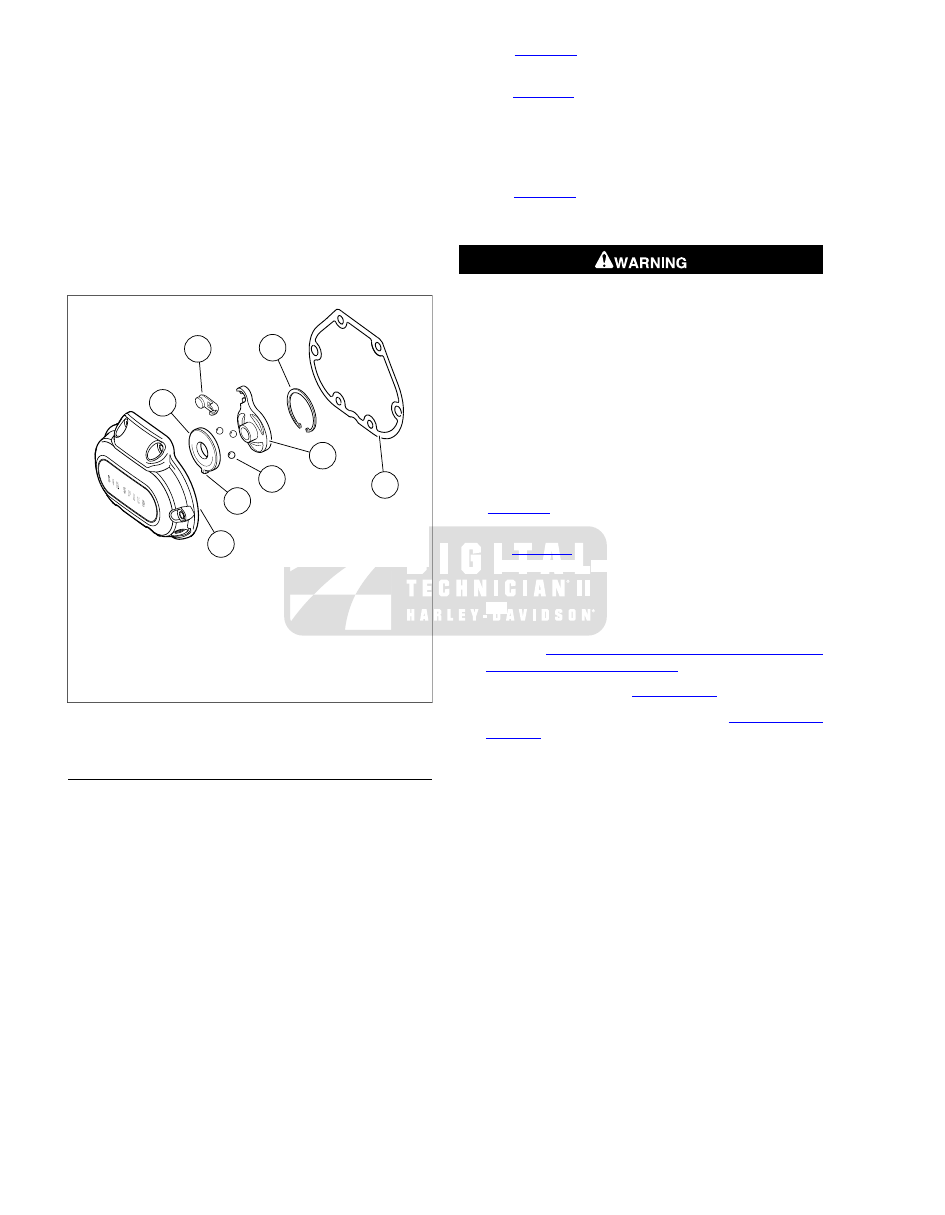
2.
Inspect the three balls (2) and ball socket surfaces on
ramps (1, 3) for wear, pitting, surface breakdown and other
damage. Replace damaged parts.
3.
Check fit of the ramp coupling (4) on inner ramp (1).
Replace both parts if there is excessive wear.
4.
Inspect the retaining ring (6) for damage or distortion.
5.
Check clutch cable end for frayed or worn ends. Replace
cable if damaged or worn. Check cable fitting o-ring for
cuts, tears or signs of deterioration.
6.
Check the bore in the cover (5) where the ramps (1, 3)
are retained. There should be no wear that would cause
the ramps to cock, causing improper clutch adjustment.
1
6
7
4
8
5
2
3
sm03010
1.
Inner ramp
2.
Balls (3)
3.
Outer ramp
4.
Ramp coupling
5.
Clutch release cover
6.
Retaining ring
7.
Gasket
8.
Tab
Figure 7-6. Release Mechanism Assembly
ASSEMBLY AND INSTALLATION
NOTE
Replace cable fitting o-ring if damaged or deformed.
1.
See
. Screw clutch cable fitting (1) into clutch
release cover. Do not tighten at this time.
2.
. Place outer ramp (3) with ball socket side
up in clutch release cover. Be sure tab (8) is in clutch
release cover slot.
3.
Apply a multi-purpose grease to the balls and outer ramp
sockets. Place a ball in each of the outer ramp sockets.
4.
See
. Connect cable end to ramp coupling (3).
Install coupling on inner ramp (5) and place inner ramp
and coupling in position in clutch release cover.
Wear safety glasses or goggles when removing or
installing retaining rings. Retaining rings can slip from the
pliers and could be propelled with enough force to cause
serious eye injury. (00312a)
NOTE
Retaining ring opening (6) must be centered above the break
in the ribbing at bottom of the clutch release cover.
5.
Install retaining ring (4).
6.
Verify that two dowel pins are in place on transmission
side door flange. Place a new gasket on dowel pins.
NOTE
See
. Clutch release cover screws in positions (1)
and (6) are shorter than the others.
7.
. Install clutch release cover. Tighten screws
to 84-108 in-lbs (9.5-12.2 Nm) in sequence shown.
8.
Tighten clutch cable fitting to 90-120 in-lbs (10.2-13.6
Nm).
9.
Fill transmission to proper level with fresh transmission
fluid. See
1.10 TRANSMISSION LUBRICANT, Transmis-
sion Lubrication: Touring Models
.
10. Adjust clutch cable. See
.
11. Install exhaust system if removed. See
.
12. Install maxi-fuse.
7-6 2008 Touring Service: Transmission