Harley Davidson 2008 Touring Models. Service Manual - page 23
 

  Главная      Harley Davidson     Harley Davidson 2008 Touring Models. Service Manual


Search            copyright infringement  


Content      ..     21      22      23      24     ..


Harley Davidson 2008 Touring Models. Service Manual - page 23


1

2

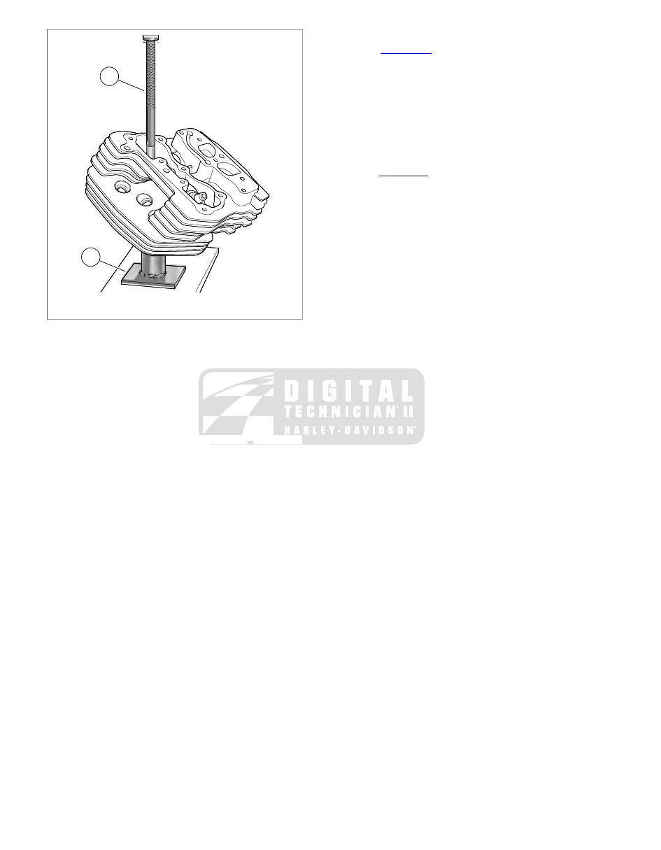
sm02498

1.

Valve guide driver

2.

Cylinder head stand

Figure 3-84. Remove Valve Guide

Installation

1.

Check valve guide to valve bore clearance.

a.

Measure the outside diameter of a new standard valve
guide.

b.

Measure the cylinder head valve guide bore. The
valve guide should be  0.0020-0.0033 in. (0.051-0.084
mm) larger than the bore.

c.

If clearance is not within specification, then select one
of the following oversize guides: 0.001 in. (0.025
mm),  0.002 in. (0.05 mm) or  0.003 in. (0.08 mm).

NOTE

Since some material is typically removed when the guide is
pressed out, it is normal to go to the next larger size for the
proper interference fit.

2.

Measure cylinder head bore and outside diameter of
selected oversize guide to verify correct interference fit.

NOTE

Support stand ensures that valve guide and seat are perpen-
dicular. If perpendicularity is not achieved, cylinder head valve
guide bore will be damaged during the press procedure.

3.

Prepare cylinder head for valve guide replacement.

a.

See 

Figure 3-83

. Insert sleeve of INTAKE SEAT

ADAPTER (Part No. HD-39782-3) (3) or EXHAUST
SEAT ADAPTER (Part No. HD-39782-4) (4) into tube
at top of support stand (2). Position cylinder head so
that valve seat is centered on seat adapter.

b.

Apply Vaseline to lightly lubricate external surfaces
of valve guide. Spread lubricant so that thin film
covers entire surface area.

c.

At top of cylinder head, start valve guide into bore.

d.

See 

Figure 3-85

. Place VALVE GUIDE INSTALLER

SLEEVE (Part No. B-45524-2A) (2) over valve guide
and then insert tapered end of valve guide driver (1)
into sleeve.

e.

Center valve guide driver under ram of arbor press
and apply pressure only until valve guide is started
in bore and then back off ram slightly to allow guide
to center itself.

NOTE

Always back off ram to allow the valve guide to find center.
Pressing guide into cylinder head in one stroke can bend
driver, break guide, distort cylinder head casting and/or
damage cylinder head valve guide bore.

f.

Verify that support stand (3) and driver (1) are square.
Center driver under ram and press valve guide further
into bore, but then back off ram again to allow valve
guide to find center.

g.

Repeat previous step and then apply pressure to
driver until installer sleeve contacts machined area
of cylinder head.

h.

Install new lock ring into valve guide groove. Verify
that lock ring is square and fully seated in the groove.

3-66  2008 Touring Service:  Engine

1

3

2

2

1

sm02299

1.

Valve guide driver

2.

Valve guide installer sleeve

3.

Cylinder head stand

Figure 3-85. Install Valve Guide

4.

Secure cylinder head for service.

a.

Thread 12 mm end of CYLINDER HEAD HOLDING
FIXTURE (Part No. HD-39786) into cylinder head
spark plug hole.

b.

Clamp tool in vise at a 45 degree angle or one that
offers a comfortable working position.

NOTE

Valve guides must be reamed to within  0.0005-0.0001
in. (0.013-0.0025 mm) of finished size.

2

1

sm02499

1.

T-handle

2.

Valve guide reamer

Figure 3-86. Reaming Valve Guide Bore

5.

See 

Figure 3-86

. Obtain the VALVE GUIDE

REAMER (Part No. B-45523), REAMER T-HANDLE (Part
No. HD-39847) and REAMER LUBRICANT (Part No. HD-
39964).

a.

Install T-handle (1) on reamer (2).

b.

Apply a liberal amount of reamer lubricant to valve
guide bore and bit of reamer. Start bit of reamer into
bore at top of cylinder head.

c.

Placing thumb on drive socket of reamer T-handle,
apply slight pressure on reamer while rotating in a
clockwise direction. Squirt additional lubricant onto
reamer and into guide as necessary.

NOTE

For best results, do not push on reamer or apply pressure
to the reamer handle. While excessive pressure results in
a rough cut, bore will be tapered if pressure is not centrally
applied.

d.

Continue rotating reamer T-handle until entire bit has
passed through valve guide bore and shank of reamer
rotates freely.

e.

Remove T-handle from reamer, and carefully pulling
on bit, draw shaft of reamer out combustion chamber
side of valve guide.

Compressed air can pierce the skin and flying debris from
compressed air could cause serious eye injury. Wear
safety glasses when working with compressed air. Never
use your hand to check for air leaks or to determine air
flow rates. (00061a)

6.

Direct compressed air into the valve guide bore to remove
any metal shavings or debris.

7.

See 

Figure 3-87

. Clean valve guide bore with the VALVE

GUIDE CLEANING BRUSH (Part No. HD-34751).

2008 Touring Service:  Engine  3-67

8.

See 

Figure 3-88

. Obtain the VALVE GUIDE HONE (Part

No. B-45525) and REAMER LUBRICANT (Part No.HD-
39964).

a.

Install hone in a high speed electric drill.

b.

Apply reamer lubricant to finishing stones of hone and
valve guide bore.

c.

Start finishing stones of hone into bore.

d.

Activating the drill, move the entire length of the fin-
ishing stone arrangement forward and backward
through the bore for 10 to 12 complete strokes. Work
for a crosshatch pattern of approximately 60°.

9.

Direct compressed air into the valve guide bore to remove
any debris. Clean with the VALVE GUIDE CLEANING
BRUSH (Part No. HD-34751).

NOTE

Always verify valve stem to valve guide clearance after honing,
since a worn reamer may cut the bore undersize.

10. Check valve stem to valve guide clearance.

a.

Measure the inside diameter of the valve guide with
an inside ball micrometer.

b.

Measure the outside diameter of the valve stem with
an outside micrometer.

c.

Refer to 

Table 3-35

. If the clearance between stem

and guide is not within the limits shown, the low end
being preferable, then the valve stem may be
excessively worn or the valve guide bore undercut.

sm02500

Figure 3-87. Scrubbing Valve Guide Bore

sm02501

Figure 3-88. Honing Valve Guide Bore

11. Clean cylinder head assembly again.

a.

Using cleaning solvent, thoroughly clean cylinder head
and valve guide bore.

b.

Scrub valve guide bore with the VALVE GUIDE
CLEANING BRUSH (Part No. HD-34751). For best
results, use a thin engine oil and clean valve guide
bore with the type of swabs or patches found in gun
cleaning kits.

c.

Continue to wipe bore until clean cloth shows no
evidence of dirt or debris. Follow up with a thorough
wash in hot soapy water.

Compressed air can pierce the skin and flying debris from
compressed air could cause serious eye injury. Wear
safety glasses when working with compressed air. Never
use your hand to check for air leaks or to determine air
flow rates. (00061a)

12. Blow parts dry with low pressure compressed air.

Table 3-35. Valve Stem to Guide Clearance

MM

IN.

VALVE

0.0254-0.0762

0.001-0.003

Intake

0.0254-0.0762

0.001-0.003

Exhaust

3-68  2008 Touring Service:  Engine

VALVE AND SEAT REFACING

TOOL NAME

PART NUMBER

VALVE GUIDE CLEANING BRUSH

HD-34751

NEWAY VALVE SEAT CUTTER SET

HD-35758-C

CYLINDER HEAD HOLDING FIXTURE

HD-39786

NOTES

Verify correct valve stem to valve guide clearance before
refacing. Refer to 

Table 3-35

. If new guides must be

installed, complete that task before refacing valve seats.

This procedure is not based on the lapping of valves. The
end result is an interference fit between the 45° valve face
and the valve seat which will be 46°.

1.

Hold the valve firmly against a wire wheel in a bench
grinder. Remove all carbon deposits from the valve head,
face and stem, but exercise caution to avoid removing any
metal. Carbon left on the stem may affect alignment in the
valve refacer. Polish the valve stem with steel wool or
crocus cloth to remove any marks that might be left by the
wire wheel.

2.

Install valve (both intake and exhaust) in a valve refacer
set to a 45° angle. The valve refacer is required equipment,
since accuracy in matching the angle of the valve face
with the angle of the valve seat is critical.

NOTES

Do not remove any more metal than is necessary to clean
up and true the valve face. Removing metal reduces the
service life of the valve. The amount of grinding needed
to retrue the valve is a clear indication of its condition.
Discard the valve if it cannot be quickly refaced while
maintaining a good margin. See 

Figure 3-91

Valves that

do not clean up quickly are either warped, excessively
worn or too deeply pitted to be used.

Obtain a new valve if grinding leaves the margin less than

0.0313 in (0.795 mm). A valve in this condition does not

seat normally, burns easily and may crack or cause pre-
ignition.

3.

Wipe valve seats and valve faces clean. From the bottom
of the cylinder head, insert the valve stem into the valve
guide. Push on head of valve until it contacts the valve
seat.

4.

See 

Figure 3-89

. Measure valve stem protrusion. Seat

wear causes the valve stem protrusion to change.

a.

Placing finger at bottom of valve to keep valve seated,
use a dial vernier caliper to check the distance from
the top of the valve stem to the machined area on the
cylinder head.

b.

Seat wear and valve refacing causes the valve stem
protrusion to change. If protrusion exceeds  2.069
in. (52.553 mm), then replace the valve, valve seat
or cylinder head as necessary.

NOTE

Do not shorten the valve by grinding on the end of the stem.
Grinding replaces the hardened case with mild steel which
results in accelerated wear.

5.

Secure cylinder head for servicing.

a.

Thread 12 mm end of CYLINDER HEAD HOLDING
FIXTURE (Part No. HD-39786) into cylinder head
spark plug hole.

b.

Clamp fixture in vise and further tighten cylinder head
onto the fixture to prevent any movement during
operation.

c.

Place cylinder head at a 45° angle or one that offers
a comfortable working position.

6.

In order to determine the correct location of the 46° valve
seat in the head, measure the width of the valve to be
used and subtract  0.080 in. (2.032 mm) from that number.

7.

Set your dial caliper to the lesser measurement and lock
down for quick reference. This is the location of your valve
seat.

8.

Use a permanent magic marker to highlight the valve seat
area that is going to be cut. Be sure to highlight all three
angles. Allow marker to dry before proceeding.

sm02502

Figure 3-89. Checking Valve Stem Protrusion

NOTES

Always ensure cutter blades and cutter pilot are clean
before beginning the cutting process. The correct cleaning
brush is supplied with the Neway tool set.

Always ensure the inside of the valve guide is clean by
using VALVE GUIDE CLEANING BRUSH (Part No. HD-
34751).

2008 Touring Service:  Engine  3-69

9.

See 

Figure 3-90

. Obtain the NEWAY VALVE SEAT

CUTTER SET (Part No. HD-35758-C). Choose the cutter
pilot that fits properly into the valve guide hole. Securely
seat the pilot by pushing down and turning using the
installation tool supplied in the tool set.

10. Choose the proper 46° cutter (intake or exhaust) and

gently slide the cutter onto the pilot. Be careful not to drop
the cutter onto the seat.

11. While applying a constant and consistent pressure, remove

just enough material to show a complete clean-up on the
46° angle. Do not remove any more metal than is neces-
sary to clean up the seat (that is, to provide a uniform finish
and remove pitting).

NOTES

If the width of the clean-up angle is greater on one side
of the seat than the other, the guide may need to be
replaced due to improper installation.

After making the 46° cut, if you discover a groove cut
completely around the seat, this means the blades of the
cutter are in alignment and need to be staggered. This is
accomplished by loosening all of the blades from the cutter
body and moving each blade slightly in its cradle in
opposite directions on the cutter. The tool needed to
loosen the blades is supplied in the tool set. A permanent
magic marker mark every 90° will help in determining
where new angles are.

12. Next, with your dial caliper locked to the predetermined

setting, measure the 46° cut at the outermost edge at the
widest point of the circle to determine what cut needs to
be made next.

a.

If the 46° cut is too high (towards the combustion
chamber), use the 31° cutter to lower the valve seat
closer to the port.

b.

If the 46° cut is too low, use the 60° cutter to raise the
valve seat or move it away from the port.

NOTES

Because you are using the top measurement of the valve
seat as a reference point it will usually be necessary to
use the 31° cutter following the initial 46° cut.

Always highlight the valve seat with the permanent magic
marker in order to ensure the location of the 46° valve
seat.

sm02503

Figure 3-90. Neway Valve Seat Cutter Set

13. If the location of the valve seat is not correct, repeat steps

10 and 11.

14. When you accomplish a complete clean-up of the 46°

angle and the width is at least  0.062 in. (1.575 mm), pro-
ceed to the next step.

15. Select the proper 60° cutter and gently slide the cutter

down the cutter pilot to the valve seat.

16. Remove just enough material to provide an even valve

seat width of   0.040-0.062 in. (1.016-1.575 mm).

17. Remove cutter and cutter pilot.

18. Insert valve to be used in the valve guide and bottom on

the valve seat. Positioning the cylinder head port upwards
and with slight thumb pressure against the valve, com-
pletely fill the port with solvent to verify proper seal
between the valve and the valve seat.

NOTE

Hold pressure against the valve for a minimum of 10 seconds.
If any leakage occurs, examine the valve and valve seat for
irregularities or defects and if necessary repeat the above valve
grinding or valve seat cutting process.

19. Repeat the process on any valve seat that needs service.

20. Clean valves, cylinder head and valve seats in solvent.

Follow up with a thorough wash in hot soapy water.

Compressed air can pierce the skin and flying debris from
compressed air could cause serious eye injury. Wear
safety glasses when working with compressed air. Never
use your hand to check for air leaks or to determine air
flow rates. (00061a)

21. Blow parts dry with low pressure compressed air.

3-70  2008 Touring Service:  Engine

1

3

4

5

2

sm00148

1.

Minimum: 0.040 in. (1.016 mm) / Maximum: 0.062
in. (1.575 mm)

2.

60 degrees

3.

31 degrees

4.

46 degrees

5.

Margin

Figure 3-91. Valve and Seat Dimensions

ASSEMBLY

TOOL NAME

PART NUMBER

VALVE SPRING COMPRESSOR

HD-34736-B

VALVE GUIDE CLEANING BRUSH

HD-34751

CYLINDER HEAD HOLDING FIXTURE

HD-39786

1.

Secure cylinder head for service.

a.

Thread 12 mm end of CYLINDER HEAD HOLDING
FIXTURE (Part No. HD-39786) into cylinder head
spark plug hole.

b.

Clamp tool in vise at a 45 degree angle or one that
offers a comfortable working position.

NOTE

At the time of disassembly, all parts should have been marked
or tagged so that they are installed on the same valve (and in
the same head).

2.

Run the VALVE GUIDE CLEANING BRUSH (Part No. HD-
34751) through the valve guide bore to verify cleanliness.

3.

Using TORCO MPZ or another suitable product, apply a
liberal amount of engine assembly lube to valve stem.

4.

From the bottom of the cylinder head, insert the valve stem
into the valve guide.

5.

To distribute the assembly lube evenly around the valve
stem and guide, hand spin the valve as it is installed. Work
the valve back and forth in the bore to verify that it slides
smoothly and seats properly.

6.

Remove the valve and apply a second coat of assembly
lube to the valve stem. Install the valve in the valve guide.

Failure to install plastic capsule can cause the valve stem
seal to catch the edge of the valve stem keeper groove.
The resulting damage can cause leakage around the valve
stem, excessive oil consumption and valve sticking.
(00535b)

7.

See 

Figure 3-92

. Push on bottom of valve until it contacts

the valve seat. Placing finger at bottom of valve to keep
valve seated, slide plastic capsule over valve stem tip and
keeper groove.

8.

Apply a very thin film of clean H-D 20W50 engine oil to
capsule.

9.

See 

Figure 3-93

. Obtain new valve stem seal.

10. Slide new valve stem seal/spring seat over capsule and

down valve stem until contact is made with top of valve
guide and machined area of cylinder head casting.
Remove capsule from valve stem tip.

sm02504

Figure 3-92. Plastic Capsule

sm02528

Figure 3-93. Valve Stem Seal/Spring Seat Assembly

11. See 

Figure 3-94

. Apply a liberal amount of assembly lube

to valve stem tip and keeper groove (1).

12. With the smaller diameter coils topside, install the valve

spring (3) over the valve guide (5). Place the spring
retainer (2) on top of the valve spring.

2008 Touring Service:  Engine  3-71

13. Obtain the VALVE SPRING COMPRESSOR (Part No. HD-

34736-B) and proceed as follows:

a.

Place tool over cylinder head so that the blunt end is
centered on the valve head and adapter at end of
forcing screw is seated on the valve spring retainer.

b.

Rotate forcing screw to compress valve spring.

c.

With the tapered side down, fit the keepers into the
valve stem groove. For best results, apply a dab of
grease to the inboard side of the keepers before
installation and use a magnetic rod for easy place-
ment.

d.

Arranging tapered keepers so that the gaps are evenly
spaced, turn forcing screw to release valve spring
compression.

14. Tap the end of the valve stem once or twice with a soft

mallet to ensure that tapered keepers are tightly seated
in the valve stem groove.

15. Repeat previous steps to install the other valve compon-

ents.

16. Release the cylinder head holding fixture from the vise.

Remove fixture tool from spark plug hole.

17. Cover the cylinder head to protect it from dust and dirt

until time of installation.

1

4

2

3

6

5

sm02505

1.

Tapered keepers

2.

Spring retainer

3.

Valve spring

4.

Spring seat/valve stem set seal

5.

Valve guide

6.

Lock ring

Figure 3-94. Valve Assembly

INSTALLATION OVERVIEW

See 

3.16 TOP END OVERHAUL: ASSEMBLY

.

1.

Install cylinder head.

2.

Install push rod covers and push rods.

3.

Install rocker arm support plate.

4.

Install breather assembly.

5.

Continue with vehicle assembly as directed.

3-72  2008 Touring Service:  Engine

3.23

CYLINDER

REMOVAL OVERVIEW

See 

3.15 TOP END OVERHAUL: DISASSEMBLY

.

1.

Remove breather assembly.

2.

Remove rocker arm support plate.

3.

Remove push rods and push rod covers. Do not remove
lifters or lifter covers.

4.

Remove cylinder head.

5.

Remove cylinder.

CLEANING

TOOL NAME

PART NUMBER

CYLINDER TORQUE PLATES

HD-42324-A

1.

See 

Figure 3-95

. Scrape old gasket material from the

machined surface at the top of the cylinder (3). Old gasket
(1) material left on the mating surface will cause leaks.

Compressed air can pierce the skin and flying debris from
compressed air could cause serious eye injury. Wear
safety glasses when working with compressed air. Never
use your hand to check for air leaks or to determine air
flow rates. (00061a)

2.

Clean cylinder in a non-volatile cleaning solution or solvent.
Blow parts dry with low pressure compressed air. Verify
that oil passageways are clean and open.

3.

Inspect the cylinder bore for defects or damage in the ring
travel area. Replace cylinders that are severely scored,
scuffed, scratched, burnt or gouged.

4.

Using Magnaflux Dye Penetrant, inspect the cylinder for
cracks. If no cracks are found, thoroughly wash cylinder
to remove traces of dye.

5.

Use a file to carefully remove any nicks or burrs from the
machined surfaces of the cylinder.

6.

See 

Figure 3-96

. Check the machined surfaces for flatness

using a feeler gauge and CYLINDER TORQUE
PLATES (Part No. HD-42324-A) as follows:

a.

Lay gasket side of the upper torque plate (3) (without
vise grip step) flat against the head gasket surface of
the cylinder.

b.

As a preliminary check, see if the plate rocks from
side to side. A cylinder on which the plate rocks is
immediately suspect.

c.

Insert a feeler gauge between the plate and cylinder
at various locations.

d.

The head gasket surface must be flat within  0.006
in. (0.15 mm).

e.

Now turn the cylinder upside down and lay the seal
side of the lower torque plate (2) (with vise grip step)
flat against the o-ring seal surface. Repeat steps 6b
and 6c above.

f.

The o-ring seal surface must be flat within  0.004
in. (0.102 mm).

g.

Replace the cylinder (and piston) if either surface is
not within specification.

4

2

5

3

1

sm02529

1.

Cylinder head gasket

2.

Dowel pin

3.

Cylinder

4.

O-ring seal

5.

Cylinder stud

Figure 3-95. Cylinder Assembly

2008 Touring Service:  Engine  3-73

INSPECTION

TOOL NAME

PART NUMBER

CYLINDER TORQUE PLATES

HD-42324-A

NOTE

Failure to use cylinder torque plates can produce measure-
ments that vary by as much as  0.001 in. (0.025 mm), possibly
resulting in the use of parts that are not suitable for service.

1.

See 

Figure 3-97

To simulate an assembled cylinder for

accurately measuring cylinder taper and out-of-round
conditions, as well as for boring, honing or deglazing,
obtain the CYLINDER TORQUE PLATES (Part No. HD-
42324-A). Install the torque plates as follows:

a.

Remove o-ring seal from cylinder sleeve, if installed.

b.

Place used head gasket over two dowel pins at top
of cylinder.

c.

See 

Figure 3-97

. Install brass jaws or shop towels

around teeth of vise to prevent damage to tool. Clamp
stepped side of lower plate in vise with the simulated
split line (machined strip) facing away.

d.

Lightly oil threads and shoulders of four bolts (1) with
clean H-D 20W50 engine oil. Slide four bolts all the
way through holes of lower plate (2).

e.

Slide cylinder down bolts with the indent in the cooling
fins facing upward.

f.

With the two dowel pins and head gasket in place,
align holes in upper plate with ends of bolts. Blind
holes in upper plate accommodate dowel pins in cyl-
inder. Tighten four bolts into upper plate until finger
tight.

g.

See 

Figure 3-98

. Tighten the bolts to 120-144 in-

lbs (13.6-16.3 Nm) in the sequence shown.

h.

Following the same sequence, tighten each bolt to
15-17 ft-lbs (20.3-23.1 Nm).

i.

Using a grease pencil, mark a straight line on one of
the bolts continuing the line over onto the lower plate.
Repeat step for remaining three bolts.

j.

Using the marks as a guide, turn each bolt 1/4 turn
or 90°. Be sure to tighten the bolts in the sequence
shown in 

Figure 3-98

.

NOTE

For best results, obtain SNAP-ON TORQUE ANGLE
GAUGE TA360.

k.

For purposes of inspection, remove the assembly
from the vise and place on bench top.

2

4

1

3

sm02506

1.

Bolts

2.

Lower plate

3.

Upper plate

4.

Vise grip step

Figure 3-96. Cylinder Torque Plates (Part No. HD-42324-A)

NOTE

Maximum cylinder wear occurs at the very top of top ring travel.
Minimum wear occurs below ring travel. Failure to measure
the cylinder at these points may result in a faulty decision
regarding the suitability of the cylinder for continued use.

2.

See 

Figure 3-99

. Using an inside micrometer or dial bore

gauge, check cylinder bore for out-of round and taper.
Proceed as follows:

a.

At the top of the piston ring travel zone, starting about

0.50 in. (12.70 mm) or from the top of the cylinder,

measure the cylinder diameter at two locations; par-
allel and perpendicular to the crankshaft. Record the
readings.

b.

Repeat the two measurements at the center of the
piston ring travel zone.

c.

Repeat the measurements again at the bottom of the
bore at a point below the piston ring travel zone.

d.

Rebore the cylinder if the parallel and perpendicular
measurements at either the top, middle or bottom of
the bore vary by more than   0.002 in. (0.051 mm).
This indicates an out-of-round condition.

e.

Rebore the cylinder if the top, middle and bottom bore
diameters either parallel or perpendicular to the
crankshaft vary by more than  0.002 in. (0.051 mm).
This indicates excessive taper.

3.

Continue with cylinder service.

a.

If cylinders are not scuffed or scored and are not worn
beyond the service limits, see 

3.23 CYLINDER,

Deglazing Cylinder

.

b.

If cylinders are worn beyond the service limits, then
they must be rebored and/or honed to accept the next
standard oversize piston. See 

3.23 CYLINDER,

Boring and Honing Cylinder

.

3-74  2008 Touring Service:  Engine

6.7

DRIVE BELT

REMOVAL AND ADJUSTMENT

Adjustment

See 

1.13 REAR BELT DEFLECTION, Setting Belt Deflection

.

Removal

1.

Remove rear wheel and rear fork. See 

2.22 REAR FORK

.

2.

Remove primary chain, clutch, engine compensating
sprocket, and chain adjuster as an assembly. See

6.3 DRIVE COMPONENTS

.

3.

Remove primary chaincase housing. See 

6.4 PRIMARY

CHAINCASE HOUSING, Removal

.

4.

Remove belt from transmission sprocket.

INSTALLATION

Never bend belt forward into a loop smaller than the drive
sprocket diameter. Never bend belt into a reverse loop.
Over bending can damage belt resulting in premature
failure, which could cause loss of control and death or
serious injury. (00339a)

1.

Install belt over transmission sprocket.

2.

Install the primary chaincase housing. See 

6.4 PRIMARY

CHAINCASE HOUSING, Installation

.

NOTE

The gasket between the primary chaincase cover and chain-
case must be replaced each time the cover is removed. Failure
to replace this gasket may cause primary chaincase leaks.

3.

Install primary chain assembly and primary chaincase
cover. Fill primary chaincase with lubricant. See 

6.3 DRIVE

COMPONENTS

.

4.

Install rear fork and rear wheel. See 

2.22 REAR FORK

.

5.

Align vehicle. See 

2.11 VEHICLE ALIGNMENT

.

6.

Adjust belt tension. See 

1.13 REAR BELT DEFLECTION

.

6-22  2008 Touring Service:  Drive

7.1

SPECIFICATIONS: TRANSMISSION

SPECIFICATIONS

Table 7-1. Transmission Specifications

DATA

TRANSMISSION

6-speed forward constant

mesh

Type

Part No. 99851-05 (qt)

FORMULA+ TRANSMISSION
AND PRIMARY CHAINCASE
LUBRICANT

32 oz.

Capacity

946.4 ml

Table 7-2. Gear Specifications

OVERALL GEAR RATIO

GEAR

3.34

First (low)

2.31

Second

1.72

Third

1.39

Fourth

1.18

Fifth

1.00

Sixth (high)

NOTE

Final gear ratios indicate the number of mainshaft revolutions
required to drive the output sprocket one revolution.

SERVICE WEAR LIMITS

Table 7-3. Main Drive Gear Specifications

MM

IN.

MAIN DRIVE GEAR (6th)

0.0076-0.043

0.0003-0.0017

Bearing fit in transmission
case (loose)

0.025-0.076

0.001-0.003

Fit in bearing (press-fit)

none

none

End play

Table 7-4. Mainshaft Tolerance Specifications

MM

IN.

MAINSHAFT TOLERANCE

0.00-0.08

0.000-0.003

Mainshaft runout

none

none

Mainshaft end play

0.05-0.66

0.00-0.026

5th gear end play (axial)

0.010-0.038

0.0004-0.0015

5th gear clearance (radial)

0.023-0.056

0.0009-0.0022

Main drive gear (6th) fit

Table 7-5. Countershaft Tolerance Specifications

MM

IN.

COUNTERSHAFT
TOLERANCE

0.00-0.08

0.000-0.003

Countershaft runout

0.025-0.08

0.001-0.003

Countershaft end play

0.05-0.58

0.002-0.023

1st gear end play (axial)

0.010-0.038

0.0004-0.0015

1st gear clearance (radial)

0.05-1.02

0.002-0.40

2nd gear end play (axial)

0.0127-0.030

0.0005-0.0012

2nd gear clearance
(radial)

0.05-1.07

0.002-0.042

3rd gear end play (axial)

0.010-0.038

0.0004-0.0015

3rd gear clearance
(radial)

0.03-0.71

0.001-0.028

4th gear end play (axial)

0.010-0.038

0.0004-0.0015

4th gear clearance
(radial)

Table 7-6. Shifter Dog Wear Limit Specifications

MM

IN.

SHIFTER DOG

0.381-2.845

0.015-0.112

1st

0.533-3.454

0.021-0.136

2nd

0.356-2.997

0.014-0.118

3rd

0.838-2.921

0.033-0.115

4th

0.406-2.921

0.016-0.115

5th

0.660-3.124

0.026-0.123

6th

Table 7-7. Side Door Bearing Specifications

MM

IN.

SIDE DOOR BEARING

0.0025-0.0356

0.0001-0.0014

Fit in side door (tight)

-0.018

-0.0007

Fit on countershaft (tight)

+0.025

+0.001

Fit on countershaft (loose)

-0.018

-0.0007

Fit on mainshaft (tight)

+0.025

+0.001

Fit on mainshaft (loose)

Table 7-8. Shifter Fork Specifications

MM

IN.

SHIFTER FORKS

0.102-0.305

0.004-0.012

Shifter fork to cam groove end
play

0.102-0.330

0.004-0.013

Shifter fork to dog ring end
play

6.55

0.258

First and second gear shift
fork pad thickness wear limit

5.03

0.198

Third and fourth gear shift fork
pad thickness wear limit

6.55

0.258

Fifth and sixth gear shift fork
pad thickness wear limit

2008 Touring Service: Transmission  7-1

7.2

TRANSMISSION

POWER FLOW

See 

Figure 7-1

. The 6-speed transmission consists of two

parallel shafts supporting six gears each. The longer, or
mainshaft (7), also supports the clutch and serves as the input
shaft. The shorter shaft is called the countershaft (8).

Each gear on the mainshaft is in constant mesh with a corres-
ponding gear on the countershaft. Each of these six pairs of
gears makes up a different speed in the transmission.

The transmission gears are divided into two types, gears that
rotate with the shaft, and freewheeling gears that ride on
bearings and spin freely on the shaft. A gear that rotates with
the shaft always meshes with a freewheeling gear. Also, three
dog rings are able to slide sideways on the shaft. These dog
rings are used to change transmission speeds. The dogs, or
projections, on the sides of the dog rings, engage dogs on
adjacent freewheeling gears, transmitting power through the
transmission.

Gear shifting is accomplished by three forks which fit into
grooves machined into the dog rings that slide on the guide
hubs. The position of the shifter forks is controlled by a drum-
shaped shifter cam located in the transmission side door.

Neutral

Power is introduced to the transmission through the clutch. In
neutral, with the clutch engaged, the mainshaft 1st, 2nd, 3rd
and 4th gears are rotating, but no power is transferred to the
countershaft since countershaft 1st, 2nd, 3rd and 4th gears
are freewheeling gears.

1st Gear

When the transmission is shifted into first gear, the dog ring
between countershaft 1st and 2nd, which rotates with the
countershaft, engages countershaft 1st, which has been spin-
ning freely on the countershaft driven by mainshaft 1st.

Now countershaft 1st is no longer freewheeling, but locked to
the countershaft causing the countershaft and countershaft

6th to turn. Countershaft 6th transmits the power to the main
drive gear and the sprocket as shown (1).

2nd Gear

Second gear is engaged when the dog ring between counter-
shaft 1st and 2nd is shifted out of countershaft 1st and engages
countershaft 2nd. This locks countershaft 2nd to the counter-
shaft to complete the power flow as shown (2).

3rd Gear

Two shifter forks are used to make the shift from second to
third. One fork moves the dog ring between countershaft 1st
and 2nd to its neutral position, while another fork engages the
dog ring between countershaft 3rd and 4th with countershaft
3rd. This locks countershaft 3rd to the countershaft to complete
the power flow as shown (3).

4th Gear

Fourth gear is engaged when the dog ring between counter-
shaft 3rd and 4th is shifted out of countershaft 3rd and engages
countershaft 4th. This locks countershaft 4th to the countershaft
to complete the power flow as shown (4).

5th Gear

Two shifter forks are used to make the shift from fourth to fifth.
One fork moves the dog ring between countershaft 3rd and
4th to its neutral position, while another fork engages the dog
ring between mainshaft 5th and 6th with mainshaft 5th. This
locks mainshaft 5th to the mainshaft to complete the power
flow as shown (5).

6th Gear

The shift from fifth to sixth gear occurs when the dog ring
between mainshaft 5th and 6th is shifted out of mainshaft 5th,
and is shifted directly into the main drive gear (6th gear). The
main drive gear is locked to the mainshaft resulting in a direct
one-to-one drive ratio from the clutch to the sprocket as shown
(6).

7-2  2008 Touring Service: Transmission

8

1

2

3

4

5

6

7

sm00068

1.

First gear

2.

Second gear

3.

Third gear

4.

Fourth gear

5.

Fifth gear

6.

Sixth gear

7.

Mainshaft

8.

Countershaft

Figure 7-1. Transmission Power Flow

2008 Touring Service: Transmission  7-3

7.3

SHIFTER LINKAGE

SHIFTER ROD

The shifter rod is set at the factory and should not need
adjustment under normal circumstances. However, if full
engagement or full lever travel is not achieved, adjust the shifter
rod.

NOTE

To ensure proper gear engagement and avoid possible damage
to transmission, the shift levers should not contact the footboard
when shifting.

1.

See 

Figure 7-2

. Remove locknut, lockwasher and flat

washer to free front end of shifter rod from inner shift arm.

2.

Loosen locknuts (1) and adjust rod (2) as necessary.

3.

Install flat washer, lockwasher and locknut to fasten front
end of shifter rod to inner shift arm.

4.

Tighten locknuts (1) to 80-120 in-lbs (9.0-13.6 Nm).

1

1

2

sm03667

1.

Locknut (2)

2.

Shifter rod

Figure 7-2. Shifter Rod

7-4  2008 Touring Service: Transmission

7.4

CLUTCH RELEASE COVER

REMOVAL AND DISASSEMBLY

1.

Remove maxi-fuse.

2.

Remove exhaust system if needed. See 

4.18 EXHAUST

SYSTEM

.

3.

Drain transmission. See 

1.10 TRANSMISSION LUB-

RICANT, Transmission Lubrication: Touring Models

.

NOTE

Actuating the clutch hand lever after removing the six screws
will help break the cover free.

4.

See 

Figure 7-3

. Remove the six screws that hold the clutch

release cover in place. Remove the clutch release cover
and discard the gasket.

5.

Add freeplay to clutch cable. See 

1.11 CLUTCH, Adjust-

ment

.

Wear safety glasses or goggles when removing or
installing retaining rings. Retaining rings can slip from the
pliers and could be propelled with enough force to cause
serious eye injury. (00312a)

6.

See 

Figure 7-4

. Remove retaining ring (4). Lift inner ramp

(5) and ramp coupling (3) out of clutch release cover.
Disconnect clutch cable end (2) from the ramp coupling
(3).

7.

Remove coupling (3) from inner ramp.

8.

See 

Figure 7-5

. Remove balls (4) and outer ramp (2).

9.

Unscrew clutch cable fitting from clutch release cover.

1

6

4

3

2

5

sm03668

Figure 7-3. Clutch Release Cover Torque Sequence (Short

Screws at Locations 1 and 6)

1

4

5

6

3

2

sm03008

1.

Cable fitting

2.

Clutch cable end

3.

Ramp coupling

4.

Retaining ring

5.

Inner ramp

6.

Retaining ring opening

Figure 7-4. Clutch Cable Connection

2

4

3

1

5

sm03009

1.

Inner ramp

2.

Outer ramp

3.

Outer ramp tab

4.

Balls (3)

5.

Ramp coupling

Figure 7-5. Coupling and Ramp Assembly

CLEANING AND INSPECTION

1.

See 

Figure 7-6

Wash the ball and ramp mechanism

components in cleaning solvent.

2008 Touring Service: Transmission  7-5


Content      ..     21      22      23      24     ..