Harley Davidson Softail Delux FLSTN BIKE 2011-2015. Electrical Diagnostics - page 6
HOME
em01519
Fuse
2
B
Block
BK
R
Battery
Main
15A
40A
1
A
Battery
[64B]
1
[128B]
GND 1
R/BK
[259B] [259A]
2
BCM
Starter
R
1
1
Battery Power
Ignition
Switch
BCM Input
2
2
W/BE
5
5
W/BE
R/BK
L2
L2
Starter Solenoid Power
(Except FXS/B)
Ground
1
1
BK/GN
2
2
BK/GN
R/GN
L3
L3
System Power
W/BE
W/BE
C3
C3
Ignition Switch Input
[33A] [33B]
[20B] [20A]
Ignition
BK/GN
W
D3
D3
Neutral Switch Input
Switch
BCM Input
2
2
W/BE
W/BE
BK/GN
G4
G4
Ground
(FXS/B)
Ground
1
1
BK/GN
BK/GN
[242B] [242A]
[33A] [33B]
[20A] [20B]
[78A-1] [78B-1]
Speedometer
ECM
R/O
6
6
R/O
5
5
Battery
Ground
10
10
BK/GN
System Power
16
16
R/GN
[39B] [39A]
Ground
10
10
BK/GN
[78A-2] [78B-2]
Neutral
[131A-1] [131B-1]
Switch
BCM Input
1
1
W
ABS ECU
(If Equipped)
Ground
1
1
BK
BK
6
6
Ground
R
11
11
Battery
[131A-2] [131B-2]
R
20
20
Battery
[166B] [166A]
GND 2
GND 1
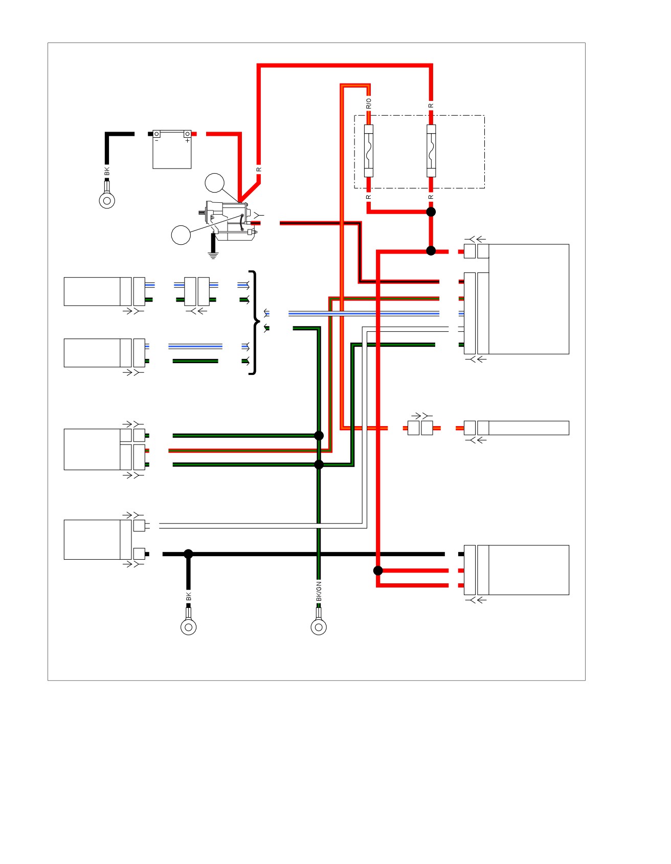
Figure 3-22. High and Low Voltage Modules
3-36 2013 Softail Diagnostics: Starting and Charging
HOME
2. Is voltage drop greater than 0.5V?
DTC B2271
a. Yes. Go to Test 6.
PART NUMBER
TOOL NAME
b. No. Repair or replace fuse block [64B] socket ter-
HD-41404
HARNESS CONNECTOR TEST KIT
minals A and B.
6. Fuse Block Supply Voltage Test
Table 3-33. DTC B2271 Diagnostic Faults
1. Perform a voltage drop test between starter terminal 1 and
POSSIBLE CAUSES
battery (+).
Charging system malfunction
2. Is voltage drop greater than 0.5V?
BCM power circuit
a. Yes. Repair or replace (R) wire between starter ter-
minal 1 and battery (+).
Open in battery power circuit
b. No. Repair or replace (R) wire between starter ter-
1. Battery Test
minal 1 and fuse block [64B] socket terminal B.
1. Perform battery test. See 3.1 BATTERY TESTING.
7. Repair Validation Test
2. Did battery pass test?
1. Clear DTCs.
a. Yes. Go to Test 2.
2. Start vehicle.
b. No. Charge or replace battery as needed. Verify
repair.
3. Run at 3000 rpm for 5 seconds.
4. Does code set?
2. Charging System Test
a. Yes. Replace BCM.
1. Perform charging system test. See
3.6 CHARGING
SYSTEM, Low or No Charging.
b. No. System working properly.
2. Is charging system working properly?
DTC B2272
a. Yes. Go to Test 3.
b. No. Repair charging system. Go to Test 7.
Table 3-34. DTC B2272 Diagnostic Faults
POSSIBLE CAUSES
3. BCM Power Test
Charging system malfunction
1. Turn IGN OFF.
2. Disconnect BCM power [259].
1. Charging System Test
1. Perform charging system tests. See
3.6 CHARGING
3. Using HARNESS CONNECTOR TEST KIT (Part No. HD-
SYSTEM.
41404), test voltage between [259B] to ground.
2. Is charging system good?
4. Is battery voltage present?
a. Yes. Go to Test 2.
a. Yes. Replace BCM.
b. No. Repair charging system.
b. No. Go to Test 4.
2. Repair Validation Test
4. Main Fuse Voltage Test
1. Perform a voltage drop test between fuse block [64B]
1. Clear DTCs.
socket terminal A and battery (+).
2. Start vehicle.
2. Is voltage drop greater than 0.5V?
3. Run at 3000 rpm for 5 seconds.
a. Yes. Go to Test 5.
4. Does DTC reset?
b. No. Repair or replace (R) wire between fuse block
a. Yes. DTC set by speedometer. Replace speedo-
[64B] socket terminal A and [259B].
meter.
5. Fuse Block Voltage Test
b. Yes. DTC set by BCM. Replace BCM.
1. Perform a voltage drop test between fuse block [64B]
c. No. System working properly.
socket terminal B and battery (+).
2013 Softail Diagnostics: Starting and Charging 3-37
NOTES
3-38 2013 Softail Diagnostics: Starting and Charging
TABLE OF CONTENTS
SUBJECT
PAGE NO.
4.1 INSTRUMENTS
4-1
4.2 DTC B1210, B1211
4-2
4.3 TRIP ODOMETER FUNCTIONS INOPERATIVE, DTC B2255
4-9
4.4 NO INSTRUMENT POWER, DTC B1200
4-12
4.5 INDICATOR LAMPS
4-17
4.6 GAUGES
4-26
NOTES
HOME
INSTRUMENTS
4.1
The odometer mileage is permanently stored and will not be
DESCRIPTION AND OPERATION
lost when electrical power is turned off or disconnected. The
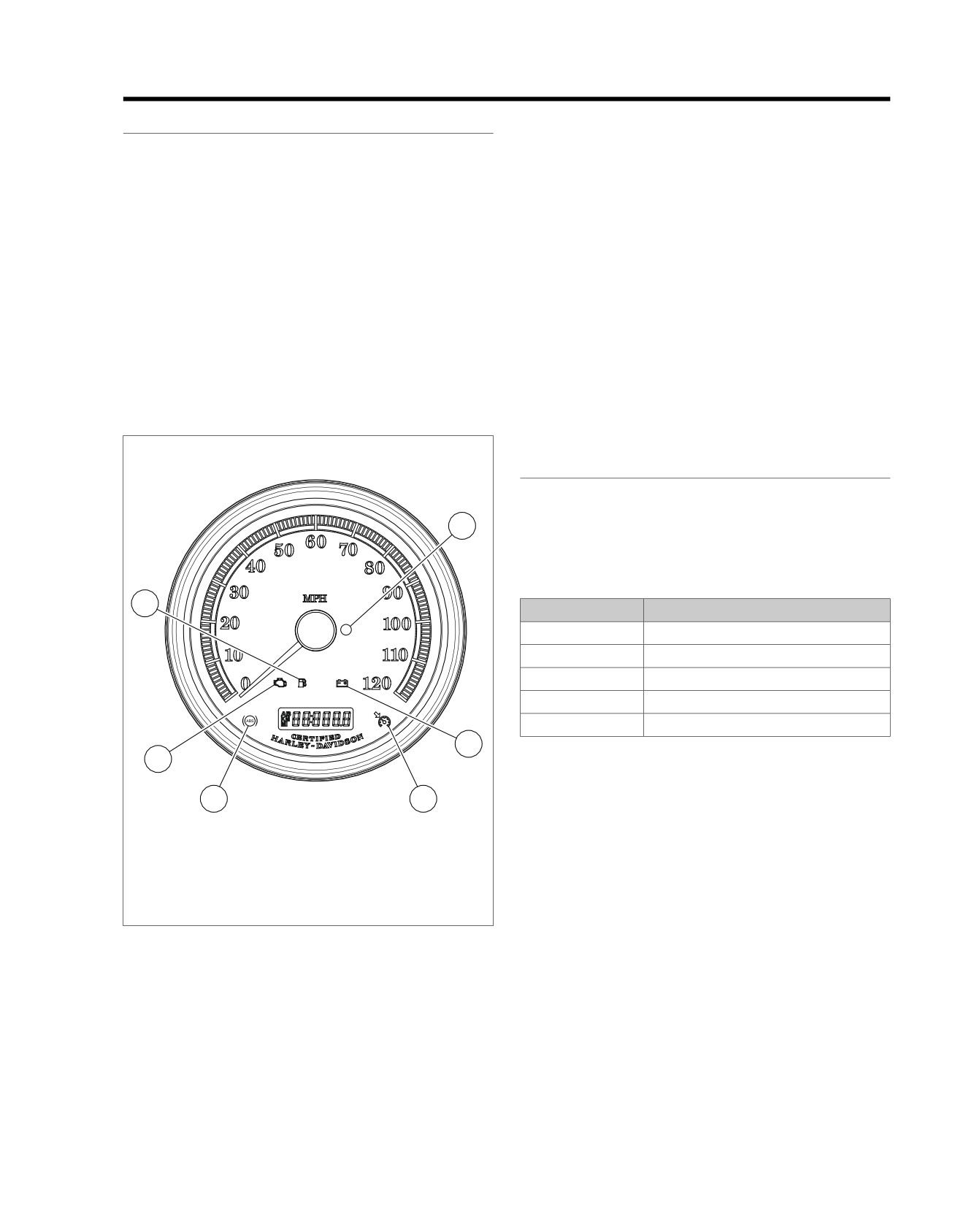
See Figure 4-1. The speedometer contains several indicators.
trip odometer reset switch allows switching between the odo-
These indicators include the check engine, security, low battery
meter, trip odometer and fuel range displays.
and low fuel lamps. The cruise control indicator may also be
To zero the trip odometer, have the odometer display visible,
shown depending on vehicle configuration.
press and keep the trip odometer reset switch depressed. The
Trip Odometer Reset Switch Operation
trip odometer mileage will be displayed for 2-3 seconds and
then the trip mileage will return to zero.
Pressing the trip odometer reset switch, located on the left
hand controls, provides the following functions:
SPEEDOMETER THEORY OF OPERATION
•
Change the odometer display between total mileage, trip
The speed sensor is mounted at the back of the transmission
odometer A and trip B, fuel range values, 12/24 hour clock
case. The sensor circuitry is a Hall-Effect sensor that is
and tachometer with gear indication.
triggered by the gear teeth of 5th gear on the transmission
•
Reset the trip odometer (press and hold 2-3 seconds).
mainshaft.
•
Gain access to self-diagnostic mode and clear diagnostic
The output from the sensor is a series of pulses that are inter-
codes. See 2.1 INITIAL DIAGNOSTICS, Odometer Self-
preted by ECM circuitry, converted into CAN bus data then
Diagnostics.
sent to the speedometer. The speedometer converts the data
to control the position of the speedometer needle. It also
provides input to the BCM for turn signal cancellation.
ed03268
INSTRUMENT DIAGNOSTICS
The speedometer monitors direct inputs from sensors and
switches, along with receiving information from the other
4
modules over the CAN bus lines. It sets codes when the
parameters for the inputs are out of range.
Table 4-1. Code Description
3
DTC
DESCRIPTION
B1200
Instrument internal fault
B1210
Fuel level sender shorted low/open
B1211
Fuel level sender shorted high
P1632
Odometer learned up
B2255
Trip switch stuck closed
5
2
1
6
1.
ABS lamp (if equipped)
2.
Check engine lamp
3.
Low fuel lamp
4.
Security lamp
5.
Battery
6.
Cruise enabled lamp (not used)
Figure 4-1. Indicator Lamps
2013 Softail Diagnostics: Instruments 4-1
HOME
DTC B1210,
B1211
4.2
DESCRIPTION AND OPERATION
ed03297
1
The fuel level is monitored by the speedometer [39] at terminal
9 (W/Y) wire. The low fuel warning lamp serves two functions.
It is used to indicate a low fuel condition and to communicate
a circuit problem with the fuel sender circuit. The speedometer
2
will flash the low fuel warning lamp on and off at a steady rate
3
when a current fuel level sender DTC is set.
•
If the voltage on terminal 9 exceeds the lower limit for
greater than or equal to 15 seconds, a DTC B1210 will be
set. The low fuel warning lamp will flash on and off at a
steady rate.
•
If the voltage on terminal 9 exceeds the upper limit (or is
4
open) for greater than or equal to 15 seconds, a DTC
B1211 will set. The low fuel warning lamp will flash on and
off at a steady rate.
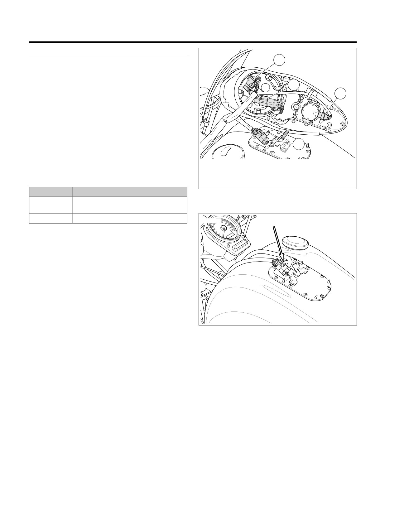
1. Speedometer [39]
2. Indicator lamps [21]
3. Ignition switch [33]
Table 4-2. Code Description
4. Fuel pump and sender [141]
DTC
DESCRIPTION
Figure 4-2. Under Console: Except FXS/B
B1210
Fuel sender shorted low/fuel gauge circuit
open
B1211
Fuel sender shorted high/open
ed03298
Voltage is supplied to the fuel level sender on the (W/Y) wire
from the fuel gauge. As the fuel level changes the resistance
of the sender changes. The fuel gauge and the low fuel lamp
are controlled through the (W/Y) wire based off the change in
the resistance of the fuel level sender.
Figure 4-3. Under Console [141]: FXS/B Typical
Connector Information
For additional information about the connectors in the following
diagram(s) and diagnostic procedure(s), including the color of
the harness test kit terminal probes, see B.1 CONNECTORS.
4-2 2013 Softail Diagnostics: Instruments
HOME
em01520
BCM
Fuel Pump
[20A] [20B]
[141B] [141A]
And
Sender
Main
R/BN
7
7
R/BN
R/BN
A
A
Fuel Pump Power
Harness
W/Y
4
4
W/Y
W/Y
B
B
Fuel Level Sender
(Except FXS/B)
BK/GN
2
2
BK/GN
BK/GN
C
C
Sender Ground
BK
8
8
BK
BK
D
D
Pump Ground
1
R/O
6
6
R/O
F4
J3
[242A]
Battery
F4
J3
[242B]
W/Y
9
9
Fuel Level
15A
BK/GN
7
7
Ground
R/O
5
5
Battery Fuse
2
[64B]
R/BN
Speedometer
W/Y
[39B] [39A]
BK/GN
Fuel Pump
BK
[13B] [13A]
[141B] [141A]
And
R/O
Sender
R/BN
R/BN
1
1
R/BN
A
A
Fuel Pump Power
W/Y
W/Y
2
2
W/Y
B
B
Fuel Level Sender
(FXS/B)
BK/GN
BK/GN
3
3
BK/GN
C
C
Sender Ground
BK
BK
4
4
BK
D
D
Pump Ground
R/O
W/Y
4
4
W/Y
9
9
Fuel Level
BK/GN
2
2
BK/GN
7
7
Ground
R/O
6
6
R/O
5
5
Battery Fuse
Speedometer
[20A] [20B]
[39B] [39A]
Main
BE
Harness
[117B] [117A]
Fuel
Gauge
BE
1
1
O
Running Light Power
(Except FXS/B)
W/Y
2
2
Y
Fuel Level Sender
BK/GN
4
4
BK
Ground
BE
W/Y
BK/GN
[200B] [200A]
Resistor
ASSY
BE
1
1
36
(FXS/B)
W/Y
2
2
36
BK/GN
3
3
200
36
GND 1
GND 2
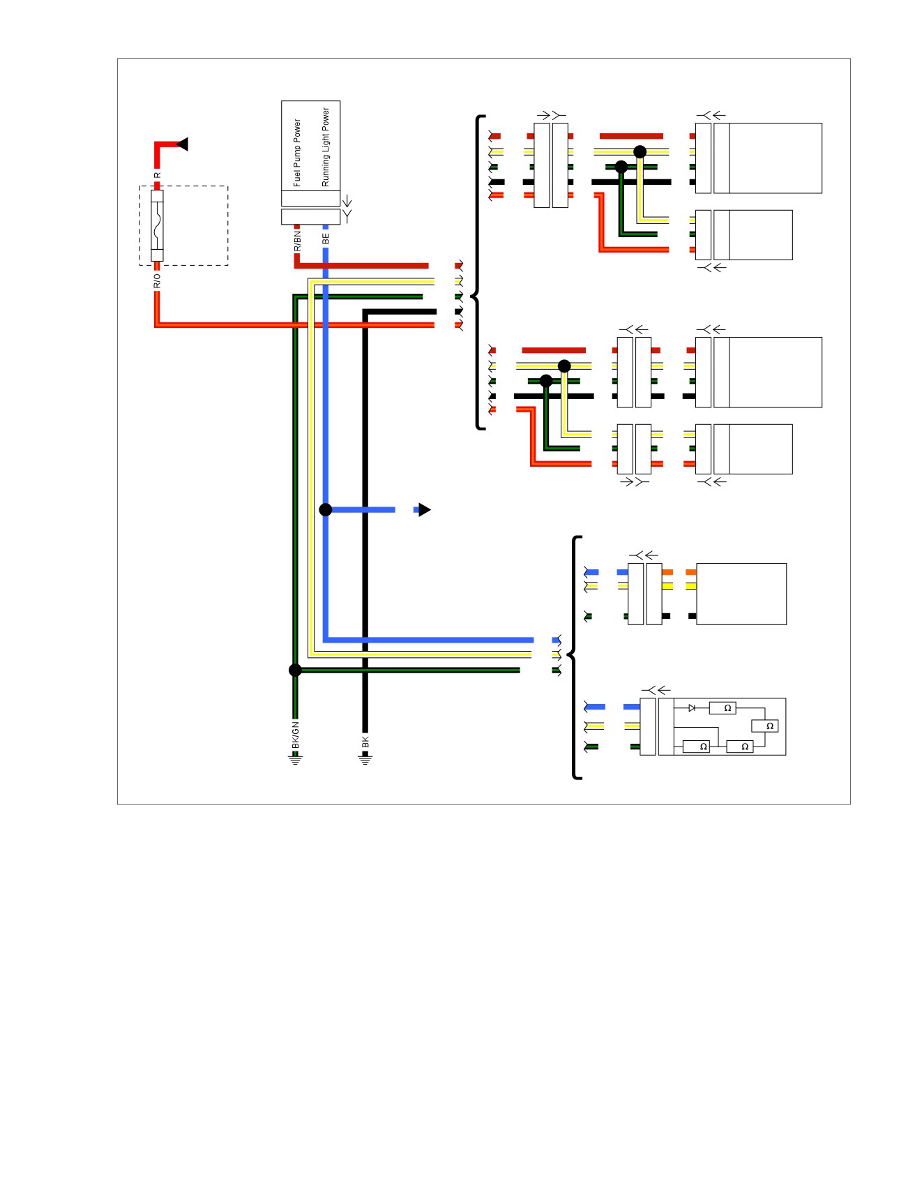
Figure 4-4. Fuel Sensor Circuit
2013 Softail Diagnostics: Instruments 4-3

HOME
3. Turn IGN ON.
DTC B1210: EXCEPT FXS/B
4. Test voltage between BOB terminal 9 and ground.
PART NUMBER
TOOL NAME
5. Is voltage greater than 2.0V?
HD-41404
HARNESS CONNECTOR TEST KIT
a. Yes. Replace speedometer.
HD-42682
BREAKOUT BOX
b. No. Go to Test 4.
HD-46601
BREAKOUT BOX ADAPTERS
HD-50390-1
BREAKOUT BOX
4. Fuel Pump and Sender Test
HD-50390-2
BCM CABLE
1. Turn IGN OFF.
HD-50390-2-P
BCM OVERLAY
2. Disconnect fuel pump and sender assembly [141].
3. Turn IGN ON.
Table 4-3. DTC B1210 Diagnostic Faults: Except FXS/B
4. Test voltage between BOB terminal 9 and ground.
POSSIBLE CAUSES
5. Is voltage greater than 2.0V?
Short to ground in fuel level sender circuit
a. Yes. Replace fuel pump and sender assembly.
Fuel level sender assembly malfunction
b. No. Go to Test 5.
Open fuel gauge circuit
5. Fuel Gauge Voltage Test
Fuel gauge malfunction
1. Turn IGN OFF.
1. BCM Test
2. Disconnect fuel gauge [117].
1. Turn IGN OFF.
3. Turn IGN ON.
2. Disconnect BCM [242].
4. Using HARNESS CONNECTOR TEST KIT (Part No. HD-
3. Connect BREAKOUT BOX (Part No. HD-50390-1) and
41404), test voltage between
[117B] terminal
1 and
BCM CABLE (Part No. HD-50390-2) between wire harness
ground.
[242B] and [242A]. See 1.2 DIAGNOSTIC TOOLS.
5. Is battery voltage present?
4. Verify BCM OVERLAY (Part No. HD-50390-2-P) is in
a. Yes. Go to Test 6.
position on BOB.
b. No. Repair open in (BE) wire between fuel gauge
5. Turn IGN ON.
terminal 1 and BCM.
6. Using the HARNESS CONNECTOR TEST KIT (Part
No. HD-41404), test voltage between BOB terminal J3
6. Fuel Gauge Circuit Test
and ground.
1. Turn IGN OFF.
7. Is battery voltage present?
2. Test continuity between [117B] terminal 2 and BOB ter-
a. Yes. Go to Test 2.
minal 9.
b. No. Replace BCM.
3. Is continuity present?
a. Yes. Go to Test 7.
2. Fuel Gauge Power Test
b. No. Repair open in (W/Y) wire between fuel gauge
1. Turn IGN OFF.
and speedometer.
2. Disconnect fuel gauge [117].
7. Fuel Gauge Circuit Test
3. Test continuity between BOB terminal J3 and [117B] ter-
minal 1 (BE) wire.
1. Test continuity between [117B] terminal 2 and ground.
4. Is continuity present?
2. Is continuity present?
a. Yes. Go to Test 3.
a. Yes. Repair short to ground in (W/Y) wire.
b. No. Repair open between [117B] terminal 1 and [242]
b. No. Replace fuel gauge.
terminal J3 (BE) wire.
3. Fuel Level Sender Voltage Test
1. Disconnect speedometer [39].
2. Connect BREAKOUT BOX ADAPTERS (Part No. HD-
46601) to [39]. Attach connectors from BREAKOUT BOX
(Part No. HD-42682) to harness adapters leaving [39A]
disconnected.
4-4 2013 Softail Diagnostics: Instruments

HOME
4. Test voltage between BOB terminal 9 and ground.
DTC B1210: FXS/B
5. Is voltage greater than 2.0V?
PART NUMBER
TOOL NAME
a. Yes. Replace speedometer.
HD-41404
HARNESS CONNECTOR TEST KIT
b. No. Go to Test 4.
HD-42682
BREAKOUT BOX
HD-46601
BREAKOUT BOX ADAPTERS
4. Fuel Pump and Sender Test
HD-50390-1
BREAKOUT BOX
1. Turn IGN OFF.
HD-50390-2
BCM CABLE
2. Disconnect fuel pump and sender assembly [141].
HD-50390-2-P
BCM OVERLAY
3. Turn IGN ON.
4. Test voltage between BOB terminal 9 and ground.
Table 4-4. DTC B1210 Diagnostic Faults: FXS/B
5. Is voltage greater than 2.0V?
POSSIBLE CAUSES
a. Yes. Replace fuel pump and sender assembly.
Short to ground in fuel level sender circuit
b. No. Go to Test 5.
Fuel level sender assembly malfunction
5. Fuel Gauge Voltage Test
Open fuel gauge circuit
1. Turn IGN OFF.
Resistor assembly malfunction
2. Disconnect resistor assembly [200].
1. BCM Test
3. Turn IGN ON.
1. Turn IGN OFF.
4. Using HARNESS CONNECTOR TEST KIT (Part No. HD-
2. Disconnect BCM [242].
41404), test voltage between
[200B] terminal
1 and
ground.
3. Connect BREAKOUT BOX (Part No. HD-50390-1) and
BCM CABLE (Part No. HD-50390-2) between wire harness
5. Is battery voltage present?
[242B] and [242A]. See 1.2 DIAGNOSTIC TOOLS.
a. Yes. Go to Test 6.
4. Verify BCM OVERLAY (Part No. HD-50390-2-P) is in
b. No. Repair open in (BE) wire between [200B] terminal
position on BOB.
1 and BCM.
5. Turn IGN ON.
6. Fuel Level Sender Circuit Test
6. Test voltage between BOB terminal J3 and ground.
1. Turn IGN OFF.
7. Is battery voltage present?
2. Test continuity between [200B] terminal 2 and BOB ter-
a. Yes. Go to Test 3.
minal 9.
b. No. Replace BCM.
3. Is continuity present?
2. Fuel Resistor Assembly Power Test
a. Yes. Go to Test 7.
1. Turn IGN OFF.
b. No. Repair open in (W/Y) wire between fuel gauge
and speedometer.
2. Disconnect resistor assembly [200].
3. Test continuity between BOB terminal J3 and [200B] ter-
7. Fuel Level Sender Circuit Test
minal 1 (BE) wire.
1. Test continuity between [200B] terminal 2 and ground.
4. Is continuity present?
2. Is continuity present?
a. Yes. Go to Test 3.
a. Yes. Repair short to ground in (W/Y) wire.
b. No. Repair open between [200B] terminal 1 and [242]
b. No. Replace resistor assembly.
terminal J3 (BE) wire.
3. Fuel Level Sender Voltage Test
1. Disconnect speedometer [39].
2. Connect BREAKOUT BOX ADAPTERS (Part No. HD-
46601) to [39]. Attach connectors from BREAKOUT BOX
(Part No. HD-42682) to harness adapters leaving [39A]
disconnected.
3. Turn IGN ON.
2013 Softail Diagnostics: Instruments 4-5
HOME
5. Is voltage greater than 8.0V?
DTC B1211: EXCEPT FXS/B
a. Yes. Repair short to voltage on (W/Y) wire.
PART NUMBER
TOOL NAME
b. No. Replace fuel pump and sender assembly.
HD-41404
HARNESS CONNECTOR TEST KIT
4. Fuel Level Sender Circuit Open Test
HD-42682
BREAKOUT BOX
1. Turn IGN OFF.
HD-46601
BREAKOUT BOX ADAPTERS
2. Disconnect fuel level sender [141].
Table 4-5. DTC B1211 Diagnostic Faults: Except FXS/B
3. Test for continuity between [117B] terminal 2 and [141B]
terminal B.
POSSIBLE CAUSES
4. Is continuity present?
Open ground circuit
a. Yes. Go to Test 5.
Short to voltage in fuel level sensor circuit
b. No. Repair open in (W/Y) wire between fuel gauge
Fuel gauge malfunction
and fuel level sender.
Fuel level sender malfunction
5. Fuel Level Sender Ground Circuit Test
Open fuel level sender circuit
1. Test continuity between [141B] terminal C and ground.
1. Fuel Level Sender Voltage Test
2. Is continuity present?
1. Turn IGN OFF.
a. Yes. Go to Test 6.
2. Disconnect speedometer [39].
b. No. Repair open in (BK/GN) wire.
3. Connect BREAKOUT BOX ADAPTERS (Part No. HD-
46601) to [39]. Attach connectors from BREAKOUT BOX
6. Fuel Gauge Ground Circuit Test
(Part No. HD-42682) to harness adapters leaving [39A]
1. Test continuity between [117B] terminal 4 and ground.
disconnected.
2. Is continuity present?
4. Turn IGN ON.
a. Yes. Go to Test 7.
5. Using the HARNESS CONNECTOR TEST KIT (Part
No. HD-41404), test voltage between BOB terminal 9 and
b. No. Repair open between [117] terminal 4 (BK/GN)
ground.
wire and ground.
6. Is voltage greater than 8.0V?
7. Fuel Sender Resistance Test
a. Yes. Go to Test 2.
1. Test resistance between [141A] terminals B and terminal
b. No, voltage between 2-8V. Replace speedometer.
C.
c. No, voltage below 2V. Go to Test 8.
2. Is resistance greater than 260 Ohms?
a. Yes. Replace the fuel level sender.
2. Fuel Pump and Sender Test
b. No. Replace the fuel gauge.
1. Turn IGN OFF.
2. Disconnect fuel gauge [117].
8. Fuel Gauge Voltage Test
1. Turn IGN OFF.
3. Turn IGN ON.
2. Disconnect fuel gauge [117].
4. Test voltage between BOB terminal 9 and ground.
3. Turn IGN ON.
5. Is voltage greater than 8.0V?
a. Yes. Go to Test 3.
4. Test voltage between [117B] terminal 1 and ground.
b. No. Go to Test 4.
5. Is battery voltage present?
a. Yes. Go to Test 9.
3. Fuel Level Sender Circuit Short to Voltage
b. No. Repair open in (BE) wire between fuel gauge
Test
terminal 1 and BCM.
1. Turn IGN OFF.
9. Fuel Gauge Test
2. Disconnect fuel level sender [141].
1. Turn IGN OFF.
3. Turn IGN ON.
2. Test continuity between [117B] terminal 2 and BOB ter-
4. Test voltage between BOB terminal 9 and ground.
minal 9.
4-6 2013 Softail Diagnostics: Instruments
HOME
3. Is continuity present?
4. Test voltage between BOB terminal 9 and ground.
a. Yes. Replace fuel gauge.
5. Is voltage greater than 8.0V?
b. No. Repair open in (W/Y) wire between fuel gauge
a. Yes. Repair short to voltage on (W/Y) wire.
and speedometer.
b. No. Replace fuel pump and sender assembly.
DTC B1211: FXS/B
4. Fuel Level Sender Circuit Open Test
PART NUMBER
TOOL NAME
1. Turn IGN OFF.
HD-41404
HARNESS CONNECTOR TEST KIT
2. Disconnect fuel level sender [141].
HD-42682
BREAKOUT BOX
3. Test continuity between [200B] terminal 2 and [141A] ter-
minal B.
HD-46601
BREAKOUT BOX ADAPTERS
4. Is continuity present?
a. Yes. Go to Test 5.
Table 4-6. DTC B1211 Diagnostic Faults: FXS/B
b. No. Repair open in (W/Y) wire between resistor
POSSIBLE CAUSES
assembly and fuel level sender.
Open ground circuit
Short to voltage in fuel level sensor circuit
5. Fuel Level Sender Ground Circuit Test
Fuel level sender malfunction
1. Test continuity between [141B] terminal C and ground.
Open fuel level sender circuit
2. Is continuity present?
a. Yes. Go to Test 6.
1. Fuel Level Sender Voltage Test
b. No. Repair open in (BK/GN) wire.
1. Turn IGN OFF.
2. Disconnect speedometer [39].
6. Resistor Assembly Ground Circuit Test
3. Connect BREAKOUT BOX ADAPTERS (Part No. HD-
1. Test continuity between [200B] terminal 3 and ground.
46601) to [39]. Attach connectors from BREAKOUT BOX
2. Is continuity present?
(Part No. HD-42682) to harness adapters leaving [39A]
a. Yes. Go to Test 7.
disconnected.
b. No. Repair open between [200] terminal 3 (BK/GN)
4. Turn IGN ON.
wire and ground.
5. Using the HARNESS CONNECTOR TEST KIT (Part
No. HD-41404), test voltage between BOB terminal 9 and
7. Fuel Sender Resistance Test
ground.
1. Test resistance between [141A] terminals B and terminal
6. Is voltage greater than 8.0V?
C.
a. Yes. Go to Test 2.
2. Is resistance greater than 260 Ohms?
b. No, voltage between 2-8V. Replace speedometer.
a. Yes. Replace fuel level sender.
c. No, voltage below 2V. Go to Test 8.
b. No. Replace resistor assembly.
2. Fuel Pump and Sender Test
8. Resistor Assembly Voltage Test
1. Turn IGN OFF.
1. Turn IGN OFF.
2. Disconnect resistor assembly [200].
2. Disconnect resistor assembly [200].
3. Turn IGN ON.
3. Turn IGN ON.
4. Test voltage between BOB terminal 9 and ground.
4. Test voltage between [200B] terminal 1 and ground.
5. Is voltage greater than 8.0V?
5. Is battery voltage present?
a. Yes. Go to Test 3.
a. Yes. Go to Test 9.
b. No. Go to Test 4.
b. No. Repair open in
(BE) wire between resistor
assembly terminal 1 and BCM.
3. Fuel Level Sender Circuit Short to Voltage
Test
9. Resistor Assembly Test
1. Turn IGN OFF.
1. Turn IGN OFF.
2. Disconnect fuel level sender [141].
2. Test continuity between [200B] terminal 2 and BOB ter-
minal 9.
3. Turn IGN ON.
2013 Softail Diagnostics: Instruments 4-7
HOME
3. Is continuity present?
b.
No. Repair open in (W/Y) wire between resistor
assembly and speedometer.
a. Yes. Replace resistor assembly.
4-8 2013 Softail Diagnostics: Instruments
HOME
TRIP ODOMETER FUNCTIONS INOPERATIVE,
DTC B2255
4.3
DESCRIPTION AND OPERATION
then the odometer self-diagnostics will not function prop-
erly.
PART NUMBER
TOOL NAME
•
Disconnect DIGITAL TECHNICIAN II (Part No. HD-48650)
before entering odometer self-diagnostics.
HD-48650
DIGITAL TECHNICIAN II
Table 4-7. Code Description
Trip Odometer Reset Switch Closed
DTC B2255 will be set if trip odometer reset switch is closed
DTC
DESCRIPTION
for more than two minutes. This code can be set by the
B2255
Trip switch stuck
speedometer or the BCM. It will normally be set by both if there
is a concern with the trip odometer reset switch.
Connector Information
Odometer self-diagnostics will not function if the switch is stuck
For additional information about the connectors in the following
since it won't be possible to toggle the switch to navigate
diagram(s) and diagnostic procedure(s), including the color of
through the different diagnostic steps in the odometer.
the harness test kit terminal probes, see B.1 CONNECTORS.
•
A stuck trip odometer reset switch disables odometer self-
diagnostics.
•
If DIGITAL TECHNICIAN II (Part No. HD-48650) is con-
nected to the DLC [91] and communicating with the vehicle
2013 Softail Diagnostics: Instruments 4-9
HOME
em01517
Left
Right
Hand
Hand
Controls
Controls
[24B] [24A]
[22A-1] [22B-1]
R/O
1
1
R/O
R/O
1
1
R/O
BK
2
2
BK/GN
BK/GN
2
2
BK
W/R
3
3
W/R
W/R
3
3
W/R
W/BK
4
4
W/BK
W/BK
4
4
W/BK
[242B] [242A]
[78A-1] [78B-1]
W/BE
C3
C3
Ignition Switch Input
CAN Low
13
13
W/BK
W/BK
E2
E2
CAN Low
CAN High
14
14
W/R
W/R
D2
D2
CAN High
Ground
10
10
BK/GN
BK/GN
G4
G4
Ground
BCM
ECM
Ground
10
10
BK/GN
R/GN
L3
L3
System Power
Battery Fuse
18
18
R/O
R
1
1
Battery Fuse
System Power
16
16
R/GN
[259B] [259A]
[78A-2] [78B-2]
W/R
1
Main
R/GN
DLC
Wiring
W/BK
3
[91A]
[20A] [20B]
[39B] [39A]
W/R
1
1
W/R
W/R
2
2
CAN High
W/BK
3
3
W/BK
W/BK
8
8
CAN Low
[166A] [166B]
BK/GN
2
2
BK/GN
BK/GN
7
7
Ground
CAN High
18
18
W/R
R/O
6
6
R/O
R/O
5
5
Battery Fuse
CAN Low
19
19
W/BK
Speedometer
ABS
Battery Power
20
20
R
W/BE
5
5
W/BE
Battery Power
11
11
R
(Except
Ground
6
6
[33B] [33A]
BK
FXS/B)
BK/GN
Ground
Ignition
BK/GN
Switch
W/BE
BCM Input
GND 2
W/BE
[33B] [33A]
BK/GN
BK/GN
1
1
Ground
Ignition
(FXS/B)
Switch
W/BE
W/BE
2
2
BCM Input
GND 1
Battery
Power
Battery
Fuse
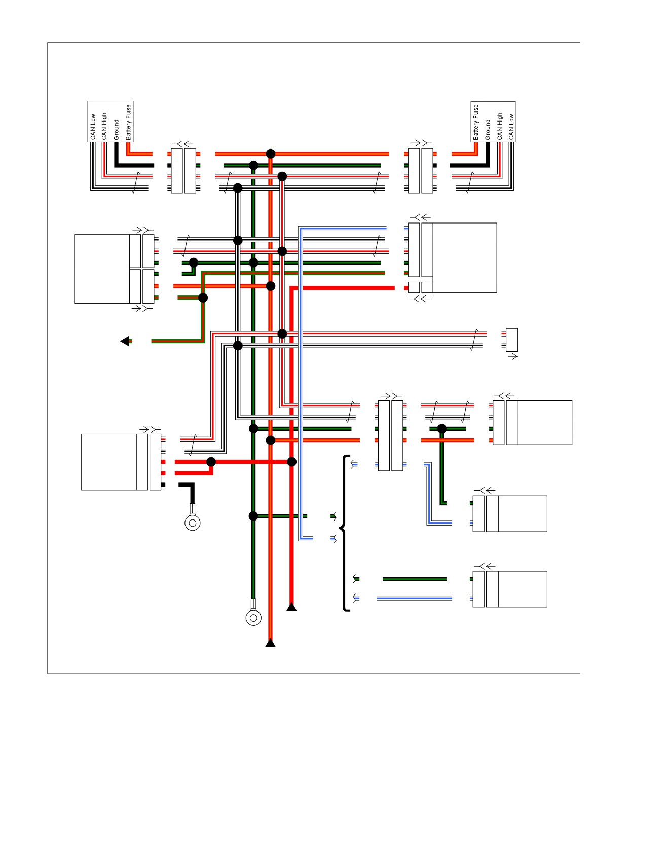
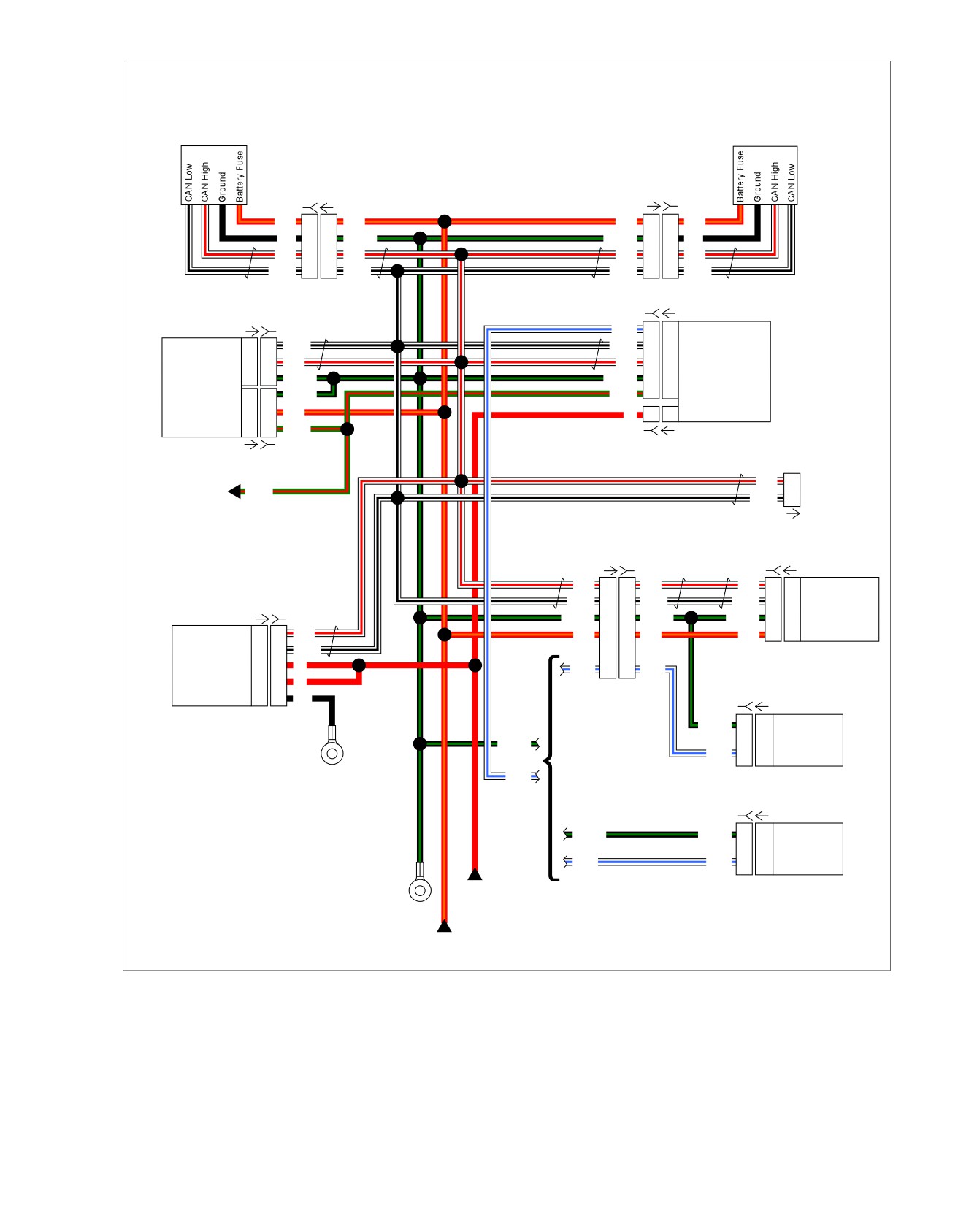
Figure 4-5. CAN Bus Circuit
4-10 2013 Softail Diagnostics: Instruments
HOME
3. Does the odometer cycle through the different odometer
TRIP ODOMETER FUNCTIONS
counters?
INOPERATIVE, DTC B2255
a. Yes. Go to Test 2.
Table 4-8. Trip Odometer Functions Inoperative, DTC
b. No. Go to Test 3.
B2255 Diagnostic Faults
3. Speedometer "WOW" Test
POSSIBLE CAUSES
1. Turn IGN OFF.
Instrument malfunction
2. Turn IGN ON, while pressing trip odometer reset switch.
Trip odometer reset switch malfunction
3. Does speedometer needle sweep its full range of motion?
1. Trip Switch Test
a. Yes. System functioning properly. Test for intermittent
1. Check trip switch for damage or obstruction.
condition.
See
1.3
DIAGNOSTICS AND
TROUBLESHOOTING, Wiggle Test.
2. Is switch moving freely?
b. No. Replace speedometer.
a. Yes. Go to Test 2.
b. No. Remove obstruction, if switch will not move freely
4. LHCM Test
replace LHCM.
1. Operate other switches on the LHCM.
2. Odometer Test
2. Do any of the switches operate?
1. Turn IGN ON.
a. Yes. Replace the LHCM.
2. Press and release the trip odometer reset switch.
b. No. See 2.4 NO VEHICLE POWER OR DTC U0100,
U0121, U0140, U0141, U0142, U0156, Left Hand
Controls Inoperative: DTC U0141.
2013 Softail Diagnostics: Instruments 4-11
HOME
NO INSTRUMENT POWER,
DTC B1200
4.4
lamp (if equipped). The backlighting, odometer, neutral lamp
DESCRIPTION AND OPERATION
and low oil lamp also illuminate with the IGN ON.
See Figure 4-6. The speedometer receives battery power at
The speedometer has an internal fault code DTC B1200. The
terminal 5. This is supplied through the battery fuse located in
speedometer will set this code if it detects a malfunction inside
fuse block [64]. The speedometer receives a message from
the speedometer.
the BCM over the CAN bus to know if the ignition switch is in
the IGN or ACC position. When the ignition switch is in the
ACC position, the speedometer illuminates the backlighting,
Table 4-9. Code Description
the odometer and the security lamp.
DTC
DESCRIPTION
When the ignition switch is in the IGN position, the speedometer
B1200
Instrument internal fault
illuminates the check engine, low fuel level, security and ABS
ed03300
1
2
3
4
5
12
11
6
10
7
8
9
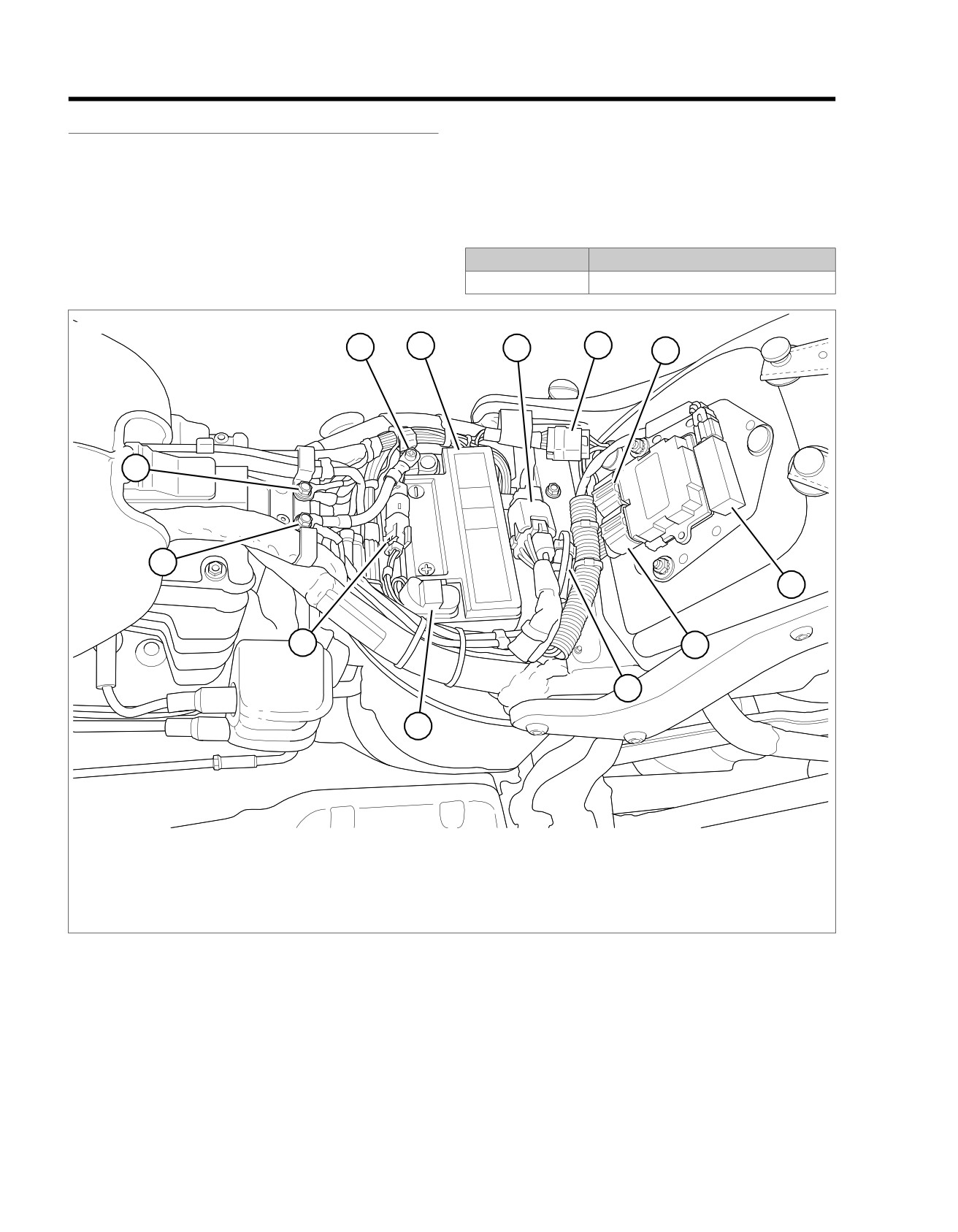
1. Battery negative
7. ECM [78B-2]
2. Battery
8. DLC [91]
3. Fuse block [64]
9. Battery positive
4. Tail lamp harness to main harness [7]
10.
Rear HO2 sensor [137]
5. ECM [78B-1]
11. Ground [GND1]
6. Security antenna [209]
12. Ground [GND2]
Figure 4-6. Under Seat: Except FXS/B and FLS
4-12 2013 Softail Diagnostics: Instruments
HOME
ed03468
2
3
4
5
1
15
14
6
7
8
13
9
10
11
12
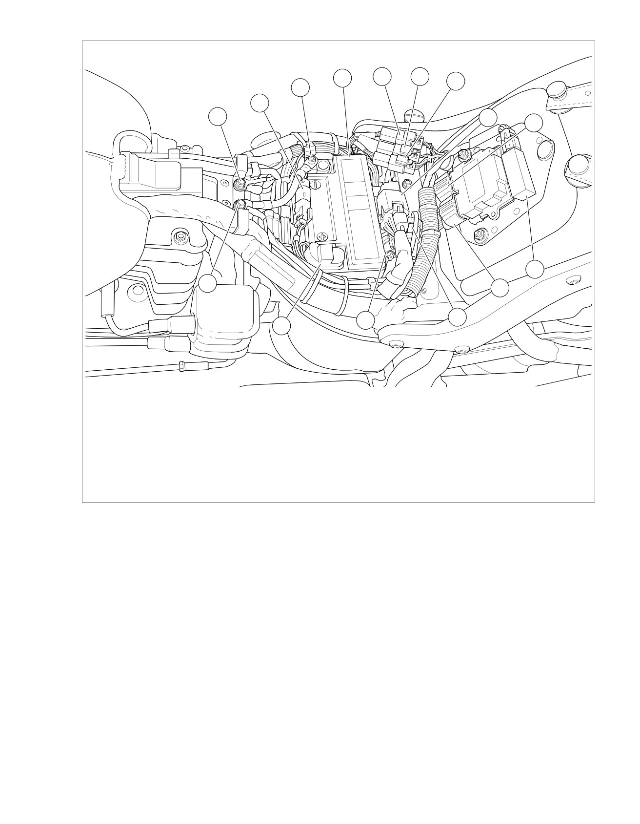
1. Battery negative
9. ECM [78B-2]
2. Battery
10. DLC [91]
3. Tail lamp harness to main harness [40]
11. Fuel sender/pump jumper harness [13]
4. Left rear stop/tail/turn harness to main harness
12. Battery positive
[19]
13. Ground [GND1]
5. Right rear stop/tail/turn harness to main harness
14. Ground [GND2]
[18]
15. Rear HO2 sensor [137]
6. Fuse block [64]
7. ECM [78B-1]
8. Security antenna [209]
Figure 4-7. Under Seat: FXS and FLS
2013 Softail Diagnostics: Instruments 4-13
HOME
ed03415
2
3
4
5
6
1
7
8
11
9
10
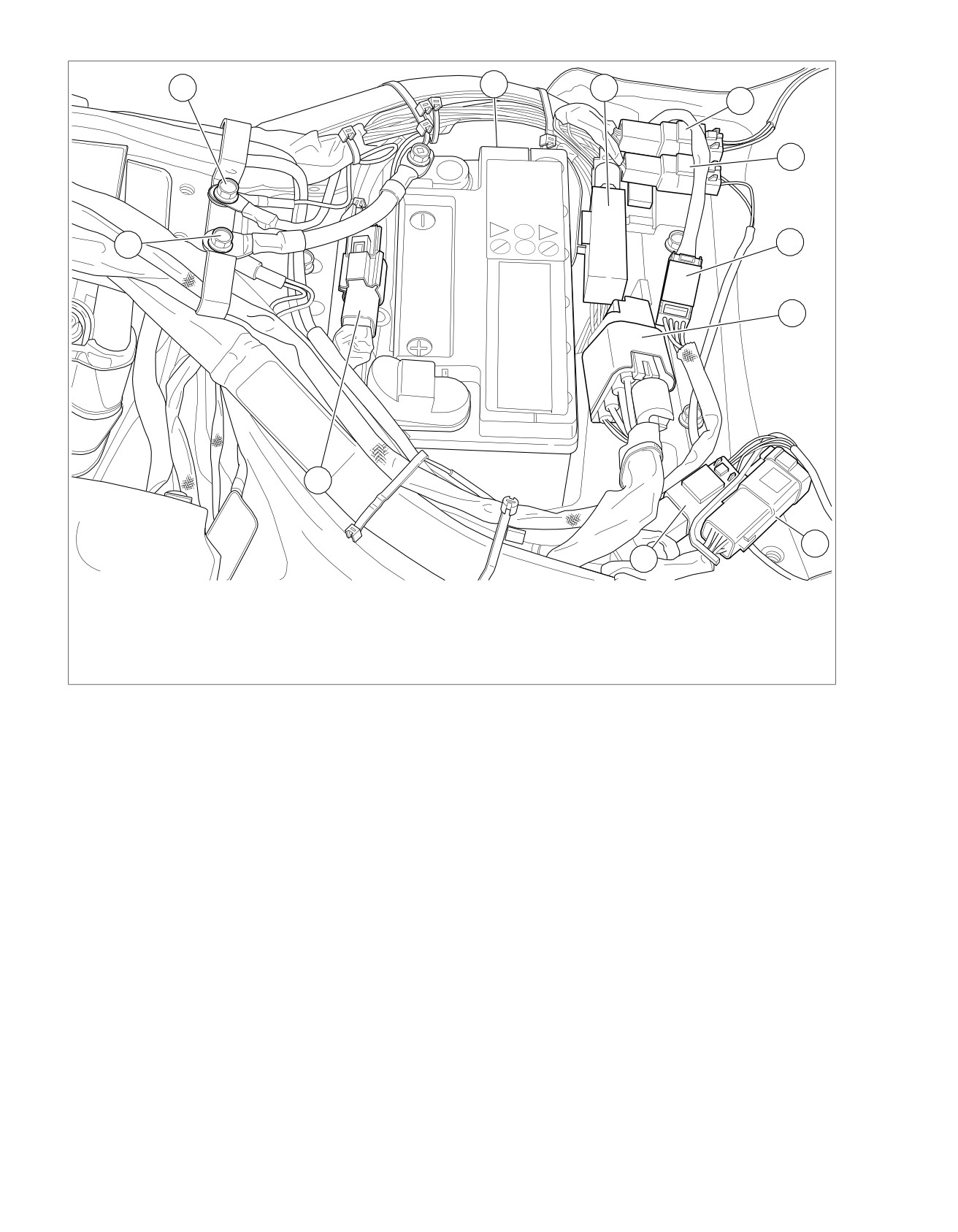
1. GND 1
7. Fuel pump/sender [13]
2. GND 2
8. Fuse block connector [64]
3. Resistor pack [200] (behind battery)
9. DLC [91]
4. Security antenna connector [209]
10. Left rear lighting [19]
5. Right rear lighting [18]
11. Rear HO2S [137]
6. Tail/LP lamp [45]
Figure 4-8. Under Seat: FXSB
Connector Information
For additional information about the connectors in the following
diagram(s) and diagnostic procedure(s), including the color of
the harness test kit terminal probes, see B.1 CONNECTORS.
4-14 2013 Softail Diagnostics: Instruments
HOME
em01517
Left
Right
Hand
Hand
Controls
Controls
[24B] [24A]
[22A-1] [22B-1]
R/O
1
1
R/O
R/O
1
1
R/O
BK
2
2
BK/GN
BK/GN
2
2
BK
W/R
3
3
W/R
W/R
3
3
W/R
W/BK
4
4
W/BK
W/BK
4
4
W/BK
[242B] [242A]
[78A-1] [78B-1]
W/BE
C3
C3
Ignition Switch Input
CAN Low
13
13
W/BK
W/BK
E2
E2
CAN Low
CAN High
14
14
W/R
W/R
D2
D2
CAN High
Ground
10
10
BK/GN
BK/GN
G4
G4
Ground
BCM
ECM
Ground
10
10
BK/GN
R/GN
L3
L3
System Power
Battery Fuse
18
18
R/O
R
1
1
Battery Fuse
System Power
16
16
R/GN
[259B] [259A]
[78A-2] [78B-2]
W/R
1
Main
R/GN
DLC
Wiring
W/BK
3
[91A]
[20A] [20B]
[39B] [39A]
W/R
1
1
W/R
W/R
2
2
CAN High
W/BK
3
3
W/BK
W/BK
8
8
CAN Low
[166A] [166B]
BK/GN
2
2
BK/GN
BK/GN
7
7
Ground
CAN High
18
18
W/R
R/O
6
6
R/O
R/O
5
5
Battery Fuse
CAN Low
19
19
W/BK
Speedometer
ABS
Battery Power
20
20
R
W/BE
5
5
W/BE
Battery Power
11
11
R
(Except
Ground
6
6
[33B] [33A]
BK
FXS/B)
BK/GN
Ground
Ignition
BK/GN
Switch
W/BE
BCM Input
GND 2
W/BE
[33B] [33A]
BK/GN
BK/GN
1
1
Ground
Ignition
(FXS/B)
Switch
W/BE
W/BE
2
2
BCM Input
GND 1
Battery
Power
Battery
Fuse
Figure 4-9. CAN Bus Circuit
2013 Softail Diagnostics: Instruments 4-15