Harley Davidson Softail Delux FLSTN BIKE 2011-2015. Electrical Diagnostics - page 5
HOME
ed02866
ed02867
1
1
4
4
2
2
3
3
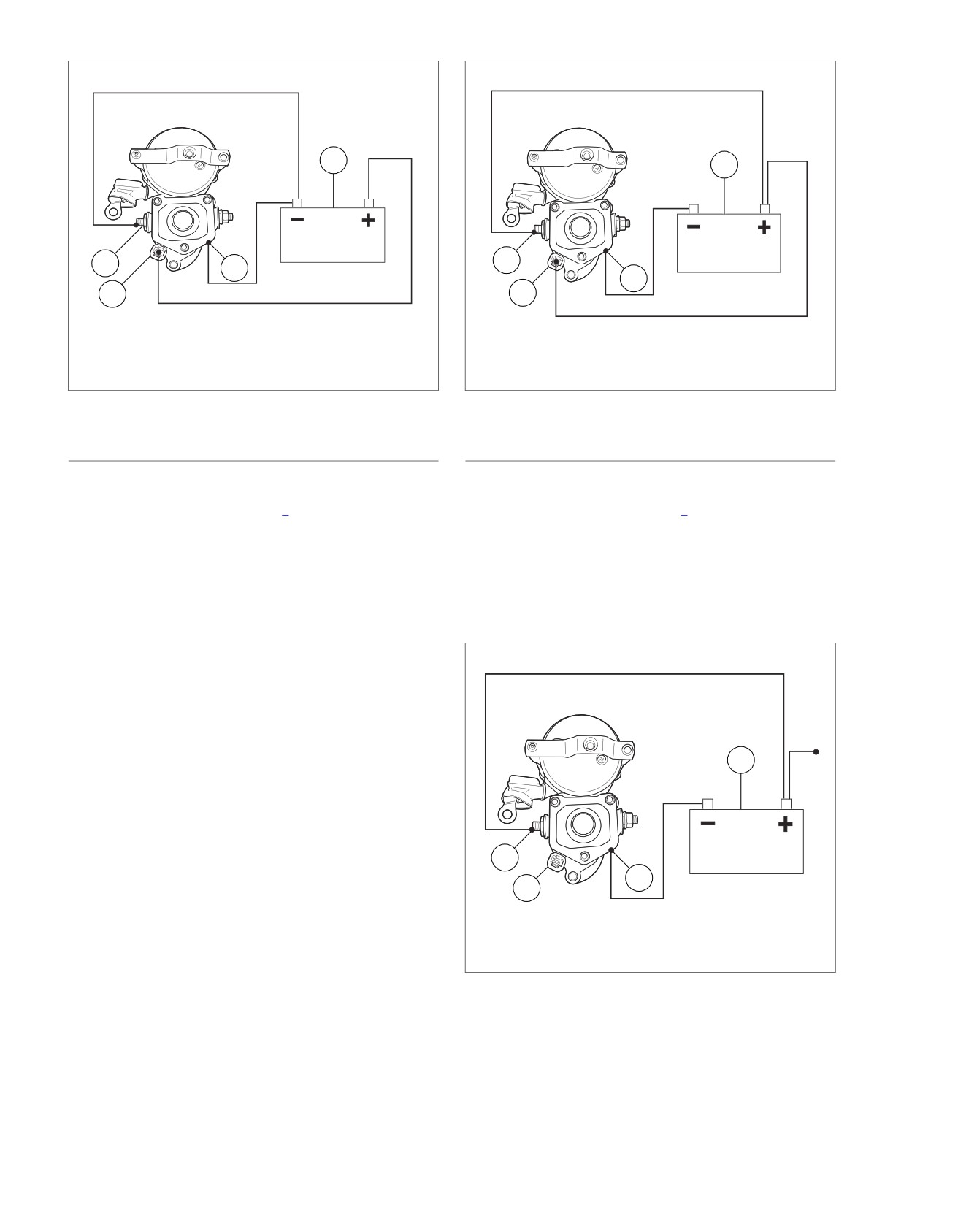
1. Battery
1. Battery
2. Solenoid housing
2. Solenoid housing
3. Solenoid relay terminal
3. Solenoid relay terminal
4. Solenoid motor terminal
4. Solenoid motor terminal
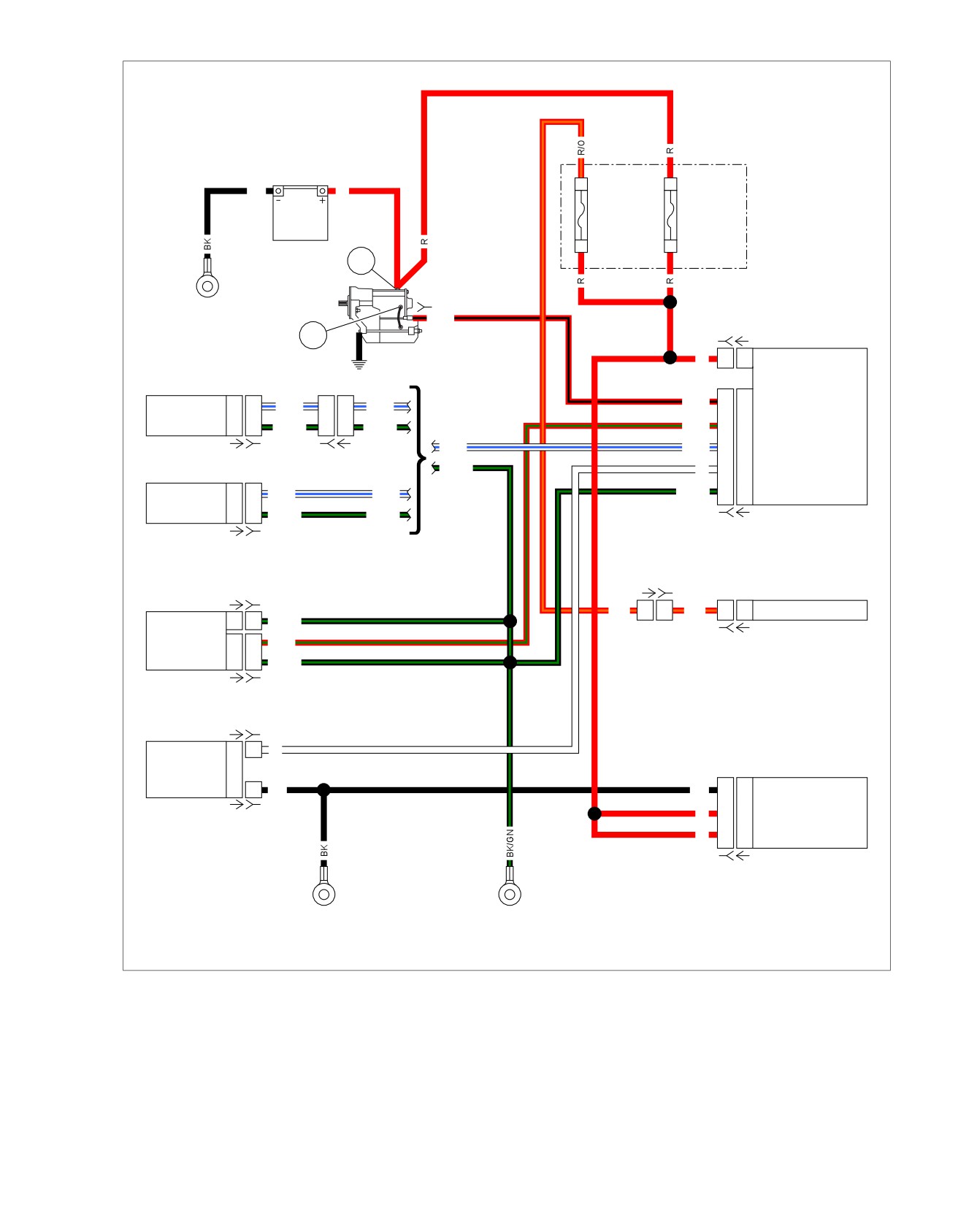
Figure 3-7. Pull-In Test
Figure 3-8. Hold-In Test
SOLENOID HOLD-IN TEST
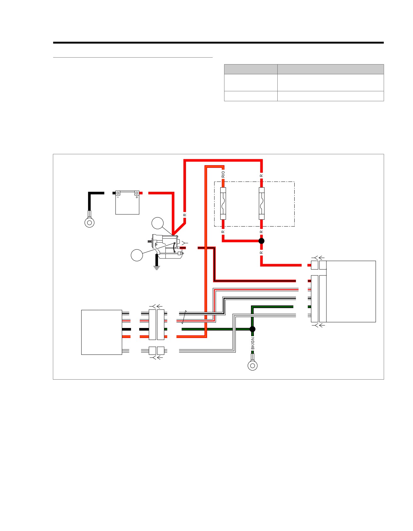
SOLENOID RETURN TEST
1. See Figure 3-8. With test leads still connected in the
1. See Figure 3-9. With test leads still connected in the
manner specified in the previous 3.5 TESTING STARTER
manner specified at the end of 3.5 TESTING STARTER
ON BENCH, Solenoid Pull-In Test, disconnect solenoid
ON BENCH, Solenoid Hold-In Test, disconnect solenoid
motor terminal/battery negative test lead at negative bat-
relay terminal/positive battery post test lead at either end.
tery post only; reconnect loose end of this test lead to
2. Observe starter pinion.
positive battery post instead.
a. If starter shaft retracts, solenoid is working properly.
2. Observe starter shaft.
b. If starter shaft does not retract, replace solenoid
a. If starter shaft remains extended, solenoid is working
assembly.
properly.
b. If starter shaft retracts, replace solenoid assembly.
ed02868
1
4
2
3
1. Battery
2. Solenoid housing
3. Solenoid relay terminal
4. Solenoid motor terminal
Figure 3-9. Return Test
3-16 2013 Softail Diagnostics: Starting and Charging
HOME
CHARGING SYSTEM
3.6
DESCRIPTION AND OPERATION
TROUBLESHOOTING
The charging system is the source of electric current that sup-
Battery
plies power to run the ignition, lights, accessories and charge
Test for a weak or dead battery. Battery must be fully charged
the battery. AC voltage is generated by an alternator assembly
in order to perform a conductance test, load test or starting or
driven by the crankshaft. A rotor supplied with a magnetic field
charging tests. See 3.1 BATTERY TESTING.
spins around a stator. A rectifier (located in the regulator)
converts the voltage from AC to DC. A regulator ensures that
Wiring
the output voltage is properly matched to the battery voltage
as engine speed varies. Even though the alternator provides
The stator connections must be clean and tight.
additional voltage at all engine speeds, it is not recommended
Check for corroded or loose connections in the charging system
to idle the vehicle for long periods of time.
circuit.
Alternator
Voltage Regulator Inspection
The alternator consists of two main components:
The voltage regulator must have clean, tight connections for
•
The rotor which mounts to the primary side of the crank-
proper operation. Verify both AC and DC connectors are fully
shaft.
inserted and locked with the regulator latch.
•
The stator which is attached to the crankcase half.
Job/Time Code Values
Dealership Technicians filing warranty claims should use the
Voltage Regulator
job/time code values printed in bold text next to the appropriate
See Figure 3-10. The voltage regulator is a series regulator.
repair.
The circuit combines the functions of rectifying and regulating.
Connector Information
For additional information about the connectors in the following
diagram(s) and diagnostic procedure(s), including the color of
the harness test kit terminal probes, see B.1 CONNECTORS.
em00869
Stator
Fuse
1
2
3
[47B]
A
Block
1
2
3
[47A]
Main
40A
Voltage
Regulator
B
[64B]
P N
[77A]
P N
[77B]
R
R
BK
Battery
Ground
GND 2
Battery
Starter
Figure 3-10. Charging System Circuit
2013 Softail Diagnostics: Starting and Charging 3-17
HOME
2. Remove center bolt and inspect for signs of the center
LOW OR NO CHARGING
hole becoming oval.
PART NUMBER
TOOL NAME
3. Verify stator bolts have not backed out and contacted the
rotor.
HD-41404
HARNESS CONNECTOR TEST KIT
4. Is rotor in good condition?
a. Yes. Go to Test 6.
Table 3-16. Low or No Charging Diagnostic Faults
b. No. Replace rotor. (5319)
POSSIBLE CAUSES
Low battery
6. Voltage Regulator Power Circuit Test
Stator malfunction
1. With IGN OFF, disconnect voltage regulator [77].
Rotor malfunction
2. Using HARNESS CONNECTOR TEST KIT (Part No. HD-
Voltage regulator malfunction
41404), test continuity between [77B] terminal + and main
fuse [5B].
Open voltage regulator circuit
Stator shorted to ground
3. Is continuity present?
AC wire shorted to ground
a. Yes. Go to Test 7.
b. No. Repair open wire between voltage regulator [77B]
1. Battery Test
terminal + and [5B]. (5041)
1. Perform battery test. See 3.1 BATTERY TESTING.
7. Voltage Regulator Ground Circuit Test
2. Did battery pass test?
NOTE
a. Yes. Go to Test 2.
The voltage regulator ground must have a clean, tight connec-
b. No. Replace battery.
tion for proper grounding.
1. Test resistance between [77B] terminal - and ground.
NOTE
2. Is resistance less than 0.5 Ohms?
A discharged battery may show a reading under 13V even
though the charging system is working properly.
a. Yes. Replace voltage regulator. (5316)
2. Off Idle Voltage Test
b. No. Repair open wire between voltage regulator [77B]
terminal - and ground (BK) wire. (5041)
1. With vehicle in neutral, start engine and run at 3000 rpm.
2. Test battery voltage.
OVERCHARGING
3. Is voltage above 13V?
PART NUMBER
TOOL NAME
a. Yes. Charging system working properly.
HD-41404
HARNESS CONNECTOR TEST KIT
b. No. Go to Test 3.
3. AC Output Test
Table 3-17. Overcharging Diagnostic Faults
1. Perform AC output test. See 3.6 CHARGING SYSTEM,
POSSIBLE CAUSES
Battery Charging Tests.
Voltage regulator malfunction
2. Did output test pass?
Open in GND 1 circuit
a. Yes. Go to Test 6.
1. Battery Voltage Test
b. No. Go to Test 4.
1. With vehicle in neutral, start engine and run at 3000 rpm,
4. Stator Test
test battery voltage.
1. Perform stator test. See 3.6 CHARGING SYSTEM, Battery
2. Is voltage above 15.5V?
Charging Tests.
a. Yes. Go to Test 2.
2. Is the stator good?
b. No. Charging system working properly.
a. Yes. Go to Test 5.
2. Voltage Regulator Ground Circuit Test
b. No. Replace stator. (5309)
NOTE
5. Rotor Inspection Test
The voltage regulator ground must have a clean, tight connec-
1. Inspect rotor for damage.
tion for proper grounding.
1. With IGN OFF, disconnect voltage regulator [77].
3-18 2013 Softail Diagnostics: Starting and Charging
HOME
2. Using HARNESS CONNECTOR TEST KIT (Part No. HD-
2. Did battery pass test?
41404), test resistance between [77B] terminal - and
a. Yes. System is working properly.
ground.
b. No. Replace battery.
3. Is resistance less than 0.5 Ohms?
a. Yes. Replace voltage regulator. (5316)
BATTERY CHARGING TESTS
b. No. Repair open wire between [77B] terminal - and
PART NUMBER
TOOL NAME
ground (BK) wire. (5041)
HD-41404
HARNESS CONNECTOR TEST KIT
LOW BATTERY AFTER EXTENDED IGN OFF
Milliampere Draw Test
Table 3-18. Low Battery After Extended IGN OFF
NOTE
Diagnostic Faults
Be sure accessories are not wired so they stay on at all times.
POSSIBLE CAUSES
This condition could drain battery completely if vehicle is parked
Battery
for a long time. Connect ammeter between x and y to test.
Accessories improperly wired to stay on at all times
1. If vehicle is equipped with security, enable service mode
before performing test.
Excessive draw from electrical component with IGN OFF
Battery self-discharge and/or component draw because
2. Disconnect the security siren (if equipped).
motorcycle was not operated for a long period
3. Remove main fuse.
1. Battery Test
NOTE
With IGN OFF, an initial current draw will occur directly after
1. Verify battery condition. See 3.1 BATTERY TESTING.
connecting meter. This should drop to the values shown in
2. Is battery condition good?
Table 3-20 in less than 30 seconds.
a. Yes. Go to Test 2.
4. See Figure 3-11. Using HARNESS CONNECTOR TEST
KIT (Part No. HD-41404), connect ammeter to main fuse
b. No. Replace battery.
socket terminals. With this arrangement, you will also pick
up any regulator drain.
2. Amp Draw Test
5. With IGN OFF and all lights and accessories off, observe
1. Perform milliampere draw test. See
3.6 CHARGING
current reading.
SYSTEM, Battery Charging Tests.
a. Add voltage regulator draw to appropriate value for
2. Did the test exceed maximum draw?
BCM and ECM. If observed ammeter reading is less
a. Yes. Repair excessive draw and run test again. (5308)
than listed in Table 3-20.
b. No. System is working properly.
b. A higher reading indicates excessive current draw.
Any accessories must be considered and checked
BATTERY RUNS DOWN DURING USE
for excessive drain.
Table 3-19. Battery Runs Down During Use Diagnostic
Table 3-20. Milliampere Draw Test
Faults
ITEM
MAXIMUM DRAW IN MILLI-
POSSIBLE CAUSES
AMPERES
Low battery
LHCM
1.0
Excessive accessory draw
RHCM
1.0
Accessories on when idling or low rpm riding for extended
Speedometer
1.0
period
T
achometer (if equipped)
1.0
1. Total Current Draw Test
Regulator
1.0
1. Perform Total Current Draw and Output Test. See
ABS (if equipped)
1.0
3.6 CHARGING SYSTEM, Battery Charging Tests.
BCM
1.0
2. Does charging system exceed current draw by 3.5A?
ECM
1.0
a. Yes. Go to Test 2.
Security siren (optional)
20.0*
b. No. System accessory power requirements exceed
* Siren will draw for 2-24 hours from time motorcycle battery
charging system capability.
is connected and 0.05 mA once siren battery is charged.
Disconnect siren during milliampere draw test.
2. Battery Test
1. Perform a battery test. See 3.1 BATTERY TESTING.
2013 Softail Diagnostics: Starting and Charging 3-19
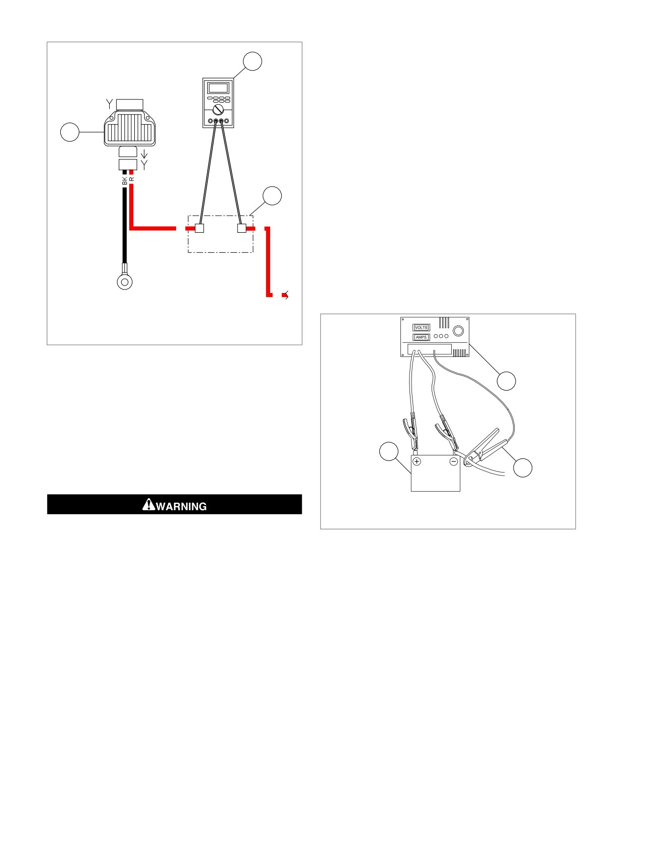
HOME
8. Remove the induction pickup from the battery negative
em00870
cable.
1
9. Place induction pickup over positive regulator cable.
10. Start engine and run at 3000 rpm.
[47A]
1
2 3
NOTE
Do not leave any load switch turned on for more than 20
3
seconds or overheating and tester damage are possible.
-
+
[77A]
11. Increase the load as required to obtain a constant 13.0V.
-
+
[77B]
12. Current output should be 35-50A. Make note of current
output.
2
NOTE
Rider's habits may require output test at lower rpm.
R
A
B
R
13. Compare both of these readings.
[64B]
a. The current output should exceed current draw by
3.5A minimum.
b. If output does not meet specifications, there may be
too many accessories for the charging system to
GND 2
R
handle.
1. Ammeter
2. Fuse block [64B]
ed02802
3. Voltage regulator
Figure 3-11. Milliampere Draw Test (Ignition Turned to
OFF)
1
Total Current Draw and Output Test
If battery runs down during use, the current draw of the
motorcycle components and accessories may exceed output
of the charging system.
NOTE
3
If a load tester is unavailable, use an ammeter with current
2
probe.
1. Load tester
2. Induction pickup
3. Battery
Turn battery load tester OFF before connecting tester
cables to battery terminals. Connecting tester cables with
Figure 3-12. Check Current Draw (Ignition Switch On)
load tester ON can cause a spark and battery explosion,
which could result in death or serious injury. (00252a)
Stator Test
1. See Figure 3-12. Connect load tester.
1. Turn IGN OFF.
a. Connect negative and positive leads to battery ter-
minals.
2. See Figure 3-13. Connect an ohmmeter.
b. Place load tester induction pickup over battery neg-
a. Disconnect voltage regulator connector from alternator
ative cable.
stator wiring.
b. Insert one ohmmeter lead into a stator connector
2. With IGN OFF, disconnect voltage regulator [77].
socket.
3. Start engine.
c. Attach the other lead to a suitable ground.
4. Turn all continuously running lights and accessories ON
(headlamp on high beam).
3. Test for continuity.
a. A good stator will show no continuity (open circuit)
5. Run engine at 3000 rpm and make note of the current
between all stator sockets and ground.
draw.
b. Any other reading indicates a grounded stator which
6. Turn engine OFF.
must be replaced.
7. With IGN OFF, connect voltage regulator [77].
3-20 2013 Softail Diagnostics: Starting and Charging
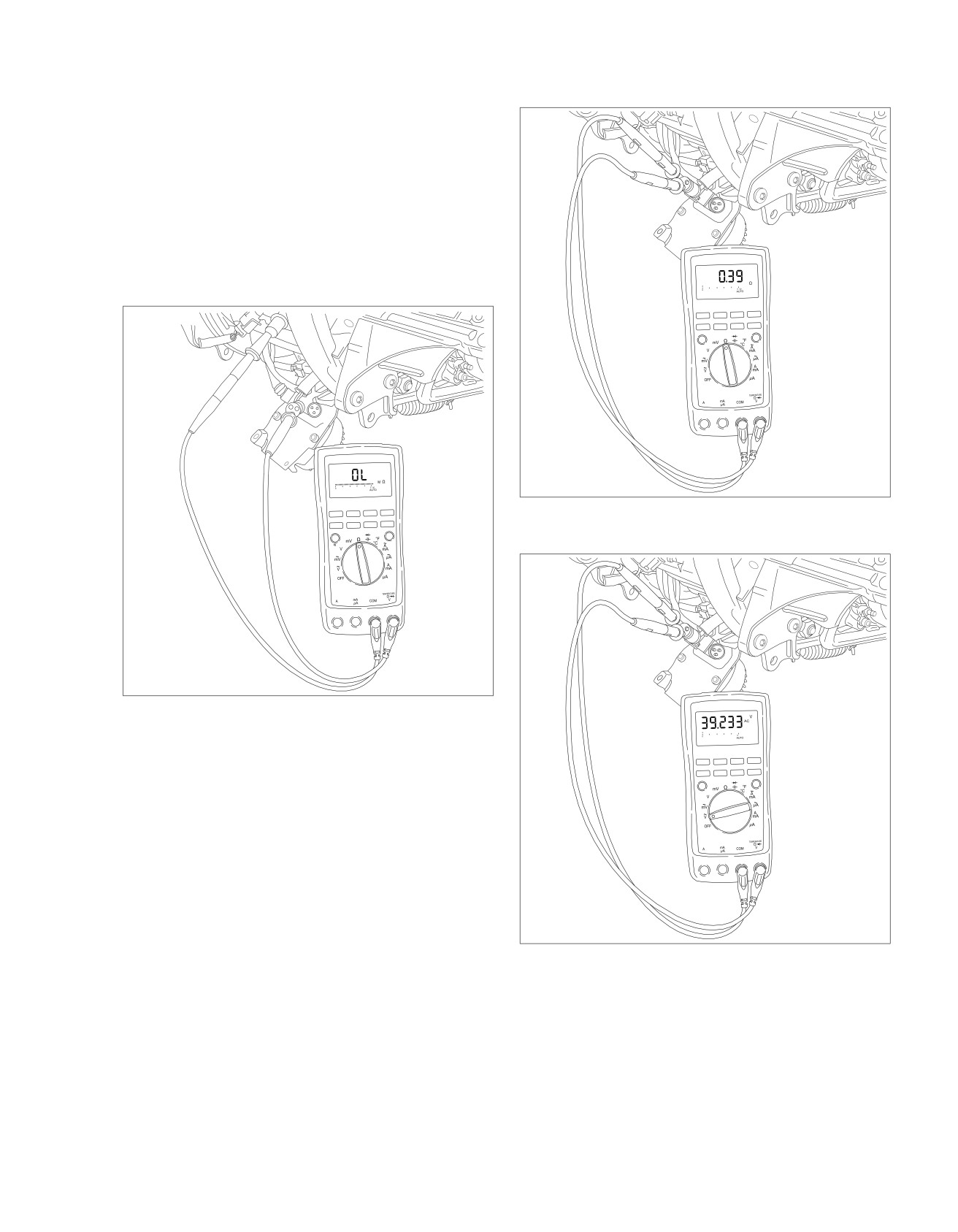
HOME
4. See Figure 3-14. Remove ground lead. Measure resist-
3. Check the output again as previously described under
ance across stator [47B] terminals 1-2, 2-3 and 3-1.
Total Current Draw and Output Test.
a. Resistance across all the stator terminals should be
0.1-0.3 Ohm.
ed03228
b. If the resistance is out of range, replace the stator.
NOTE
When measuring resistance (Ohms), compensate for test lead
resistance before performing the measurement. Select the
Ohms position and touch the test leads together. Refer to the
multimeter user's manual to either zero the display or manually
subtract the test lead resistance from the measured circuit's
value.
ed03226
Figure 3-14. Check for Stator Resistance (Typical)
ed03227
Figure 3-13. Test for Grounded Stator (Typical)
AC Output Test
1. See Figure 3-15. Test AC output.
a. Disconnect voltage regulator
[47] from alternator
stator wiring.
b. Test for VAC across stator [47B] terminals 1 to 2.
c. Run the engine at 2000 rpm. The VAC output should
be 32-46 VAC (approximately 16-22 per 1000 rpm).
d. Repeat test using terminals 2 to 3 and 1 to 3.
2. Compare test results to specifications.
Figure 3-15. Check Stator AC Voltage Output (Typical)
a. If the output is below specifications, charging problem
could be a faulty rotor or stator.
b. If output is within specifications, charging problem
might be faulty voltage regulator. Replace as required.
2013 Softail Diagnostics: Starting and Charging 3-21
HOME
DTC C0562,
C0563, C1222, C1223
3.7
DESCRIPTION AND OPERATION
Table 3-21. Code Description
Battery voltage is monitored by the ABS module. DTCs set if
DTC
DESCRIPTION
monitoring finds irregular voltage readings.
C0562
ABS voltage low
DTC C0562 and C0563
C0563
ABS voltage high
Battery voltage is monitored by the ABS module on both ter-
C1222
ABS voltage low - terminal 11
minals 11 and 20.
C1223
ABS voltage low - terminal 20
•
DTC C0562 is displayed when the ABS ECU falls below
10.5V during a non-ABS event or the ABS ECU falls below
DIAGNOSTICS
8.7V during an ABS event.
•
DTC C0563 is displayed when the ABS ECU exceeds
Diagnostic Tips
17.0V during a non-ABS event.
Any of the following conditions could cause these DTCs to set:
DTC C1222 and C1223
•
The charging system is malfunctioning.
Battery voltage is monitored by the ABS module on terminal
•
There is excessive battery draw and/or extended idling in
11 and on terminal 20.
heavy traffic.
•
DTC C1222 is displayed when the voltage of terminal 11
•
A faulty system ground is present.
falls below 2.0V of terminal 20.
•
Shorted ABS actuator circuit.
•
DTC C1223 is displayed when the voltage of terminal 20
Low voltage generally indicates a loose wire, corroded connec-
falls below 2.0V of terminal 11.
tions, battery and/or a charging system problem.
High voltage DTC may set when the vehicle is placed on an
unapproved constant current battery charger for a long period
of time.
Connector Information
For additional information about the connectors in the following
diagram(s) and diagnostic procedure(s), including the color of
the harness test kit terminal probes, see B.1 CONNECTORS.
3-22 2013 Softail Diagnostics: Starting and Charging
HOME
em01519
Fuse
2
B
Block
BK
R
Battery
Main
15A
40A
1
A
Battery
[64B]
1
[128B]
GND 1
R/BK
[259B] [259A]
2
BCM
Starter
R
1
1
Battery Power
Ignition
Switch
BCM Input
2
2
W/BE
5
5
W/BE
R/BK
L2
L2
Starter Solenoid Power
(Except FXS/B)
Ground
1
1
BK/GN
2
2
BK/GN
R/GN
L3
L3
System Power
W/BE
W/BE
C3
C3
Ignition Switch Input
[33A] [33B]
[20B] [20A]
Ignition
BK/GN
W
D3
D3
Neutral Switch Input
Switch
BCM Input
2
2
W/BE
W/BE
BK/GN
G4
G4
Ground
(FXS/B)
Ground
1
1
BK/GN
BK/GN
[242B] [242A]
[33A] [33B]
[20A] [20B]
[78A-1] [78B-1]
Speedometer
ECM
R/O
6
6
R/O
5
5
Battery
Ground
10
10
BK/GN
System Power
16
16
R/GN
[39B] [39A]
Ground
10
10
BK/GN
[78A-2] [78B-2]
Neutral
[131A-1] [131B-1]
Switch
BCM Input
1
1
W
ABS ECU
(If Equipped)
Ground
1
1
BK
BK
6
6
Ground
R
11
11
Battery
[131A-2] [131B-2]
R
20
20
Battery
[166B] [166A]
GND 2
GND 1
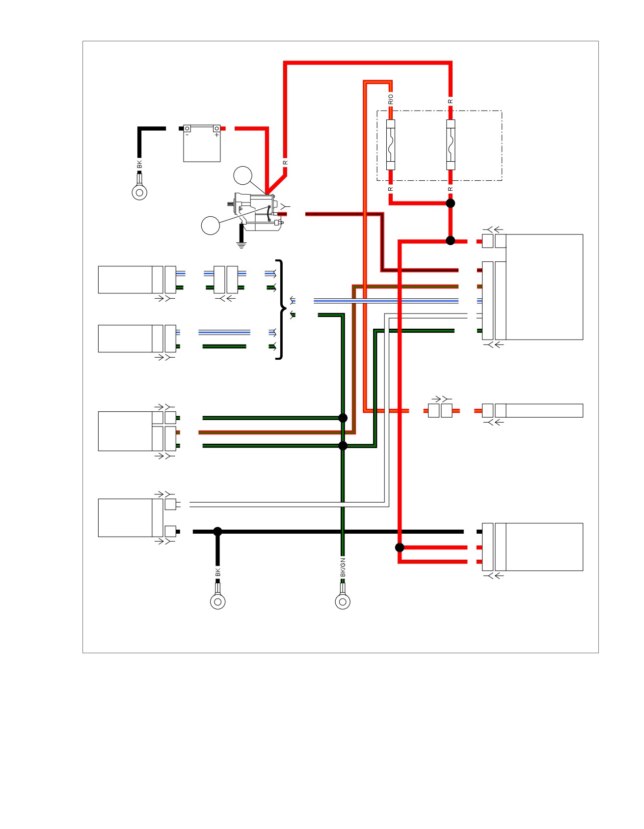
Figure 3-16. High and Low Voltage Modules
2013 Softail Diagnostics: Starting and Charging 3-23

HOME
2. Is voltage drop greater than 0.5V?
DTC C0562
a. Yes. Repair wiring between [166B] terminal 6 and
PART NUMBER
TOOL NAME
battery negative.
HD-41404
HARNESS CONNECTOR TEST KIT
b. No. Problem may be intermittent. Locate and repair
bad connection. Perform 1.3 DIAGNOSTICS AND
HD-48642
ABS BREAKOUT BOX
TROUBLESHOOTING, Wiggle Test. If no problem is
found, then continue with tests. Go to Test 9.
Table 3-22. DTC C0562 Diagnostic Faults
6. Main Fuse Voltage Drop Test
POSSIBLE CAUSES
1. Perform a voltage drop test between fuse block [64B]
Low battery
socket terminal A and battery (+).
Open ABS module ground circuit
2. Is voltage drop greater than 0.5V?
Open ABS module battery circuit
a. Yes. Go to Test 7.
1. Battery Test
b. No. Repair or replace (R) wire between [64B] socket
terminal A and BCM power [259B].
1. Perform battery test. See 3.1 BATTERY TESTING.
2. Did battery pass test?
7. Fuse Block Voltage Drop Test
a. Yes. Go to Test 2.
1. Perform a voltage drop test between [64B] socket terminal
B and battery (+).
b. No. Replace battery.
2. Is voltage drop greater than 0.5V?
2. Charging System Test
a. Yes. Go to Test 8.
1. Perform charging system test. See
3.6 CHARGING
b. No. Repair or replace [64B] socket terminals A and
SYSTEM, Low or No Charging.
B.
2. Is charging system working properly?
8. Fuse Block Supply Voltage Drop Test
a. Yes. Go to Test 3.
1. Perform a voltage drop test between starter terminal 1 and
b. No. Repair charging system.
battery (+).
3. ABS ECU Battery Voltage Test
2. Is voltage drop greater than 0.5V?
1. Turn IGN OFF.
a. Yes. Repair or replace (R) wire between starter ter-
minal 1 and battery (+).
2. Disconnect ABS module [166].
b. No. Repair or replace (R) wire between starter ter-
3. Connect ABS BREAKOUT BOX (Part No. HD-48642)
minal 1 and [64B] socket terminal B.
between wire harness [166A] and [166B]. See 1.2 DIA-
GNOSTIC TOOLS.
9. Repair Validation Test
4. With engine stop switch in the RUN position and transmis-
1. Clear DTCs.
sion in neutral, turn IGN ON.
2. Start vehicle.
5. Using HARNESS CONNECTOR TEST KIT (Part No. HD-
41404), test voltage between BOB terminals 11 and 6.
3. Run at 3000 rpm for 5 seconds.
6. Is battery voltage present?
4. Does DTC set?
a. Yes. Go to Test 9.
a. Yes. One of the ABS actuators circuit may be shorted.
See 7.6 DTC C1052, C1102 and 7.11 DTC C1192,
b. No. Go to Test 4.
C1193.
b. No. System working properly.
4. ABS ECU Battery Voltage Drop Test
1. Perform a voltage drop test between battery (+) terminal
DTC C0563
and BOB terminal 11. See 1.3 DIAGNOSTICS AND
TROUBLESHOOTING, Voltage Drop.
Table 3-23. DTC C0563 Diagnostic Faults
2. Is voltage drop greater than 0.5V?
POSSIBLE CAUSES
a. Yes. Go to Test 6.
Charging system malfunction
b. No. Go to Test 5.
1. Charging System Test
5. ABS ECU Ground Circuit Voltage Test
1. Perform charging system tests. See
3.6 CHARGING
1. Perform a voltage drop test between BOB terminal 6 and
SYSTEM.
battery (-) terminal.
3-24 2013 Softail Diagnostics: Starting and Charging
HOME
2. Is charging system good?
4. With the engine stop switch in the RUN position and the
transmission in neutral, turn the IGN ON.
a. Yes. Go to Test 2.
5. Using HARNESS CONNECTOR TEST KIT (Part No. HD-
b. No. Repair charging system. Go to Test 2.
41404), test voltage between BOB terminals 11 and 20.
2. Repair Validation Test
6. Is battery voltage present?
1. Clear DTCs.
a. Yes. Go to Test 2.
2. Start vehicle.
b. No. Repair open in (R) wire.
3. Run at 3000 rpm for 5 seconds.
2. ABS ECU Battery Voltage Drop Test
4. Does DTC C0563 set?
1. Perform a voltage drop test between breakout box ter-
a. Yes. Replace ABS module.
minals 11 and 20.
b. No. System working properly.
2. Is voltage drop greater than 0.5V?
a. Yes. Repair or replace (R) wire between fuse block
DTC C1222, C1223
[64B] socket terminal A and [166B].
b. No. Inspect [166B] for terminal pins backing out or
PART NUMBER
TOOL NAME
for fraying. Repair if necessary. Go to Test 3.
HD-41404
HARNESS CONNECTOR TEST KIT
HD-48642
BREAKOUT BOX
3. Repair Validation Test
1. Clear DTCs using odometer self-diagnostics. See
2.1 INITIAL DIAGNOSTICS, Odometer Self-Diagnostics.
Table 3-24. DTC C1222, C1223 Diagnostic Faults
2. Start vehicle.
POSSIBLE CAUSES
3. Run at 3000 rpm for 5 seconds.
Wiring harness malfunction
4. Does code set?
1. ABS ECU Battery Voltage Test
a. Yes. One of the ABS actuators circuit may be shorted.
1. Turn IGN OFF.
See 7.6 DTC C1052, C1102 and 7.11 DTC C1192,
C1193.
2. Disconnect ABS module [166].
b. No. System working properly.
3. Connect BREAKOUT BOX (Part No. HD-48642) between
wire harness [166A] and [166B]. See 1.2 DIAGNOSTIC
TOOLS.
2013 Softail Diagnostics: Starting and Charging 3-25
HOME
DTC P0562
3.8
Low voltage generally indicates a loose wire, corroded connec-
DESCRIPTION AND OPERATION
tions, battery and/or a charging system problem.
Battery voltage is monitored by the ECM on the system power
terminal 16 of [78-2]. The system power is supplied to the ECM
Connector Information
from the BCM system power terminal L3.
For additional information about the connectors in the following
DTC P0562 is displayed when battery voltage is less than
diagram(s) and diagnostic procedure(s), including the color of
12.2V at idle and voltage does not increase when engine speed
the harness test kit terminal probes, see B.1 CONNECTORS.
is greater than 2000 rpm.
Table 3-25. Code Description
DTC
DESCRIPTION
P0562
ECM voltage low
DIAGNOSTICS
Diagnostic Tips
Any of the following conditions could cause these DTCs to set:
•
The charging system is malfunctioning.
•
There is excessive battery draw and/or extended idling in
heavy traffic.
•
A faulty system ground is present.
3-26 2013 Softail Diagnostics: Starting and Charging
HOME
em01519
Fuse
2
B
Block
BK
R
Battery
Main
15A
40A
1
A
Battery
[64B]
1
[128B]
GND 1
R/BK
[259B] [259A]
2
BCM
Starter
R
1
1
Battery Power
Ignition
Switch
BCM Input
2
2
W/BE
5
5
W/BE
R/BK
L2
L2
Starter Solenoid Power
(Except FXS/B)
Ground
1
1
BK/GN
2
2
BK/GN
R/GN
L3
L3
System Power
W/BE
W/BE
C3
C3
Ignition Switch Input
[33A] [33B]
[20B] [20A]
Ignition
BK/GN
W
D3
D3
Neutral Switch Input
Switch
BCM Input
2
2
W/BE
W/BE
BK/GN
G4
G4
Ground
(FXS/B)
Ground
1
1
BK/GN
BK/GN
[242B] [242A]
[33A] [33B]
[20A] [20B]
[78A-1] [78B-1]
Speedometer
ECM
R/O
6
6
R/O
5
5
Battery
Ground
10
10
BK/GN
System Power
16
16
R/GN
[39B] [39A]
Ground
10
10
BK/GN
[78A-2] [78B-2]
Neutral
[131A-1] [131B-1]
Switch
BCM Input
1
1
W
ABS ECU
(If Equipped)
Ground
1
1
BK
BK
6
6
Ground
R
11
11
Battery
[131A-2] [131B-2]
R
20
20
Battery
[166B] [166A]
GND 2
GND 1
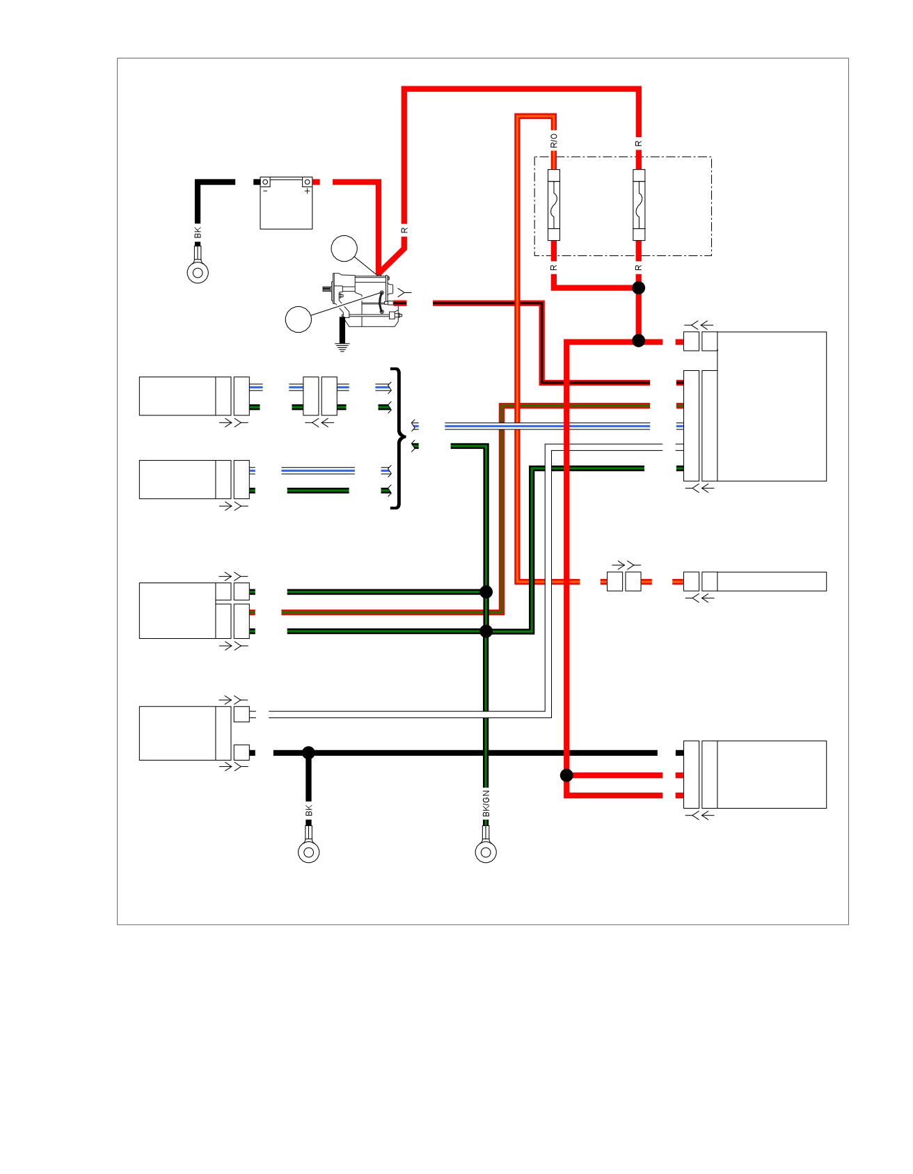
Figure 3-17. High and Low Voltage Modules
2013 Softail Diagnostics: Starting and Charging 3-27
HOME
2. Is voltage greater than 12.2V?
DTC P0562
a. Yes. Go to Test 5.
PART NUMBER
TOOL NAME
b. No. Go to Test 7.
HD-41404
HARNESS CONNECTOR TEST KIT
5. ECM Ground [78-1] Circuit Test
HD-50390-1
BREAKOUT BOX
1. Turn IGN OFF.
HD-50390-2
BCM CABLE
HD-50390-2-P
BCM OVERLAY
2. Test resistance between BOB terminal 10 of [78-1] and
ground.
HD-50390-4
ECM CABLE
3. Is resistance greater than 1 Ohm?
HD-50390-4-P
ECM OVERLAY
a. Yes. Repair wiring between ECM [78B-1] terminal 10
and ground.
Table 3-26. DTC P0562 Diagnostic Faults
b. No. Go to Test 6.
POSSIBLE CAUSES
6. ECM Ground [78-2] Circuit Test
Low battery
1. Test resistance between BOB terminal 10 of [78-2] and
Open ECM ground circuit
ground.
Open ECM system power circuit
2. Is resistance greater than 1 Ohm?
1. Battery Test
a. Yes. Repair wiring between ECM [78B-2] terminal 10
and ground.
1. Perform battery test. See 3.1 BATTERY TESTING.
b. No. Problem may be intermittent. Locate and repair
2. Did battery pass test?
bad connection. Perform 1.3 DIAGNOSTICS AND
a. Yes. Go to Test 2.
TROUBLESHOOTING, Voltage Drop. If no problem
b. No. Replace battery.
is found, then continue with tests. Go to Test 12.
2. Charging System Test
7. BCM System Power Test
1. Perform charging system test. See
3.6 CHARGING
1. Turn IGN OFF.
SYSTEM, Low or No Charging.
2. Remove BOB from ECM.
2. Is charging system working properly?
3. Connect [78A] to [78B].
a. Yes. Go to Test 3.
4. Connect the BREAKOUT BOX (Part No. HD-50390-1) and
b. No. Repair charging system.
BCM CABLE (Part No. HD-50390-2) between wire harness
[242B] and [242A]. See 1.2 DIAGNOSTIC TOOLS.
3. ECM Switched Voltage Test
5. Verify BCM OVERLAY (Part No. HD-50390-2-P) is in
1. Turn IGN OFF.
position on BOB.
2. Connect BREAKOUT BOX (Part No. HD-50390-1) and
6. Start vehicle.
ECM CABLE (Part No. HD-50390-4) to wiring harness
7. Test voltage between BOB terminal L3 and ground.
connectors [78B-1] and [78B-2]. See 1.2 DIAGNOSTIC
TOOLS.
8. Is voltage greater than 12.2V?
3. Verify ECM OVERLAY (Part No. HD-50390-4-P) is in
a. Yes. Repair (R/GN) wire between [242B] terminal L3
position on BOB.
and [78B-2] terminal 16. (5041)
4. Start vehicle.
b. No. Go to Test 8.
5. Using HARNESS CONNECTOR TEST KIT (Part No. HD-
8. BCM Power Test
41404), test voltage between BOB terminals 16 and 10 of
[78-2].
1. Turn IGN OFF.
6. Is voltage greater than 12.2V?
2. Disconnect BCM power [259].
a. Yes. System is working properly.
3. Test voltage at [259B].
b. No. Go to Test 4.
4. Is battery voltage present?
a. Yes. Replace BCM.
4. ECM System Power Test
b. No. Go to Test 9.
1. Test voltage between BOB terminal 16 of [78-2] and
ground.
9. Main Fuse Voltage Test
1. Connect [259].
3-28 2013 Softail Diagnostics: Starting and Charging
HOME
2. Turn IGN ON.
11. Fuse Block Supply Voltage Drop Test
3. Leaving main fuse in place, perform a voltage drop test
1. Perform a voltage drop test between starter terminal 1 and
between fuse block [64B] socket terminal A and battery
battery (+).
(+).
2. Is voltage drop greater than 0.5V?
4. Is voltage drop greater than 0.5V?
a. Yes. Repair or replace (R) wire between starter ter-
a. Yes. Go to Test 10.
minal 1 and battery (+).
b. No. Repair or replace (R) wire between fuse block
b. No. Repair or replace (R) wire between starter ter-
[64B] socket terminal A and [259B].
minal 1 and fuse block [64B] socket terminal B.
10. Fuse Block Voltage Drop Test
12. Repair Validation Test
1. Leaving main fuse in place, perform a voltage drop test
1. Clear DTCs.
between fuse block [64B] socket terminal B and battery
2. Start vehicle.
(+).
3. Run at 3000 rpm for 5 seconds.
2. Is voltage drop greater than 0.5V?
a. Yes. Go to Test 11.
4. Does code set?
a. Yes. Replace ECM.
b. No. Repair or replace fuse block [64B] socket ter-
minals A and B.
b. No. System working properly.
2013 Softail Diagnostics: Starting and Charging 3-29
HOME
DTC B2203
3.9
DTC B2203 is set when the BCM indicates a short to ground
DESCRIPTION AND OPERATION
between [242B] and [33B] in the (W/BE) wire.
The ignition switch turns on the BCM and the BCM then turns
on all the other components. The ignition switch has three
Table 3-27. Code Description
positions: OFF, IGN and ACC. However, there are only two
wires coming from the ignition switch. There is a ground wire
DTC
DESCRIPTION
and a signal wire that runs to the BCM.
B2203
Ignition switch input shorted low
There are two resistors built into the ignition switch:
Connector Information
•
200 Ohms for the IGN position.
For additional information about the connectors in the following
•
800 Ohms for the ACC position.
diagram(s) and diagnostic procedure(s), including the color of
The BCM will see a different voltage depending on which
the harness test kit terminal probes, see B.1 CONNECTORS.
position the ignition switch is in.
3-30 2013 Softail Diagnostics: Starting and Charging
HOME
em01519
Fuse
2
B
Block
BK
R
Battery
Main
15A
40A
1
A
Battery
[64B]
1
[128B]
GND 1
R/BK
[259B] [259A]
2
BCM
Starter
R
1
1
Battery Power
Ignition
Switch
BCM Input
2
2
W/BE
5
5
W/BE
R/BK
L2
L2
Starter Solenoid Power
(Except FXS/B)
Ground
1
1
BK/GN
2
2
BK/GN
R/GN
L3
L3
System Power
W/BE
W/BE
C3
C3
Ignition Switch Input
[33A] [33B]
[20B] [20A]
Ignition
BK/GN
W
D3
D3
Neutral Switch Input
Switch
BCM Input
2
2
W/BE
W/BE
BK/GN
G4
G4
Ground
(FXS/B)
Ground
1
1
BK/GN
BK/GN
[242B] [242A]
[33A] [33B]
[20A] [20B]
[78A-1] [78B-1]
Speedometer
ECM
R/O
6
6
R/O
5
5
Battery
Ground
10
10
BK/GN
System Power
16
16
R/GN
[39B] [39A]
Ground
10
10
BK/GN
[78A-2] [78B-2]
Neutral
[131A-1] [131B-1]
Switch
BCM Input
1
1
W
ABS ECU
(If Equipped)
Ground
1
1
BK
BK
6
6
Ground
R
11
11
Battery
[131A-2] [131B-2]
R
20
20
Battery
[166B] [166A]
GND 2
GND 1
Figure 3-18. High and Low Voltage Modules
2013 Softail Diagnostics: Starting and Charging 3-31
HOME
6. Is continuity present?
DTC B2203
a. Yes. Repair short to ground in (W/BE) wire. (5041)
PART NUMBER
TOOL NAME
b. No. Go to Test 2.
HD-41404
HARNESS CONNECTOR TEST KIT
2. Ignition Switch Run Test
HD-50390-1
BREAKOUT BOX
1. Turn IGN ON.
HD-50390-2
BCM CABLE
HD-50390-2-P
BCM OVERLAY
2. Test resistance between [33A] terminals 1 (BK/GN) wire
and 2 (W/BE) wire.
3. Is resistance between 50-400 Ohms?
Table 3-28. DTC B2203 Diagnostic Faults
a. Yes. Go to Test 3.
POSSIBLE CAUSES
b. No. Replace ignition switch. (7287)
Short in ignition switch
Ignition switch malfunction
3. Ignition Switch ACC Test
1. Turn IGN ACC.
1. Ignition Continuity [242B] Test
2. With IGN ACC, test resistance between [33A] terminals 1
1. Turn IGN OFF.
(BK/GN) wire and 2 (W/BE) wire.
2. Disconnect ignition switch [33].
3. Is resistance between 500-1900 Ohms?
3. Connect BREAKOUT BOX (Part No. HD-50390-1) and
a. Yes. Go to Test 4.
BCM CABLE (Part No. HD-50390-2) to wire harness
[242B], leaving BCM [242A] disconnected. See 1.2 DIA-
b. No. Replace ignition switch. (7287)
GNOSTIC TOOLS.
4. Ignition Switch OFF Test
4. Verify BCM OVERLAY (Part No. HD-50390-2-P) is in
1. Turn IGN OFF.
position on BOB.
2. Test continuity between [33A] terminals 1 (BK/GN) wire
5. Using HARNESS CONNECTOR TEST KIT (Part No. HD-
and 2 (W/BE) wire.
41404), test continuity between BOB terminal C3 and
ground.
3. Is continuity present?
a. Yes. Replace ignition switch. (7287)
b. No. Replace BCM.
3-32 2013 Softail Diagnostics: Starting and Charging
HOME
DTC B2206,
B2208
3.10
DESCRIPTION AND OPERATION
Table 3-29. Code Description
The RHCM is monitored by the BCM. If the communication
DTC
DESCRIPTION
between the BCM and the RHCM fails to meet normal operating
parameters, a DTC is set.
B2206
Engine stop switch input open/shorted
high
These DTCs are set outside of CAN communication and only
refer to the redundant engine stop switch (W/GY) wire from
B2208
Engine stop switch input shorted low
the RHCM.
•
DTC B2206 is set when the BCM indicates an open
between [242B] terminal C4 and the engine stop switch.
•
DTC B2208 is set when the BCM indicates a short to
ground between [242B] terminal C4 and the engine stop
switch.
em00873
Fuse
2
B
Block
BK
R
Battery
Main
15A
40A
1
A
Battery
[64B]
1
GND 1
[128B]
R/BK
[259B] [259A]
2
BCM
Starter
R
1
1
Battery Power
R/BK
L2
L2
Starter Solenoid Power
W/R
D2
D2
CAN High
W/BK
E2
E2
CAN Low
[22B-1] [22A-1]
BK/GN
G4
G4
Ground
CAN Low
W/BK
4
4
W/BK
W/GY
C4
C4
Engine Stop Switch Input
CAN High
W/R
3
3
W/R
Right
Ground
BK
2
2
BK/GN
Hand
[242B] [242A]
Controls
Battery
R/O
1
1
R/O
Engine Stop Switch
W/GY
1
1
W/GY
[22B-2] [22A-2]
GND 1
Figure 3-19. Starter
2013 Softail Diagnostics: Starting and Charging 3-33
HOME
DTC B2206
DTC B2208
PART NUMBER
TOOL NAME
PART NUMBER
TOOL NAME
HD-41404
HARNESS CONNECTOR TEST KIT
HD-41404
HARNESS CONNECTOR TEST KIT
HD-50390-1
BREAKOUT BOX
HD-50390-1
BREAKOUT BOX
HD-50390-2
BCM CABLE
HD-50390-2
BCM CABLE
HD-50390-2-P
BCM OVERLAY
HD-50390-2-P
BCM OVERLAY
Table 3-30. DTC B2206 Diagnostic Faults
Table 3-31. DTC B2208 Diagnostic Faults
POSSIBLE CAUSES
POSSIBLE CAUSES
Open in engine stop circuit
Short to ground in engine stop circuit
1. BCM Supply Voltage Test
1. BCM to Ground Continuity Test
1. With IGN OFF, disconnect RHCM [22-2].
1. With IGN OFF, disconnect RHCM [22-2].
2. Using HARNESS CONNECTOR TEST KIT (Part No. HD-
2. Using HARNESS CONNECTOR TEST KIT (Part No. HD-
41404), test voltage at [22A-2] (W/GY) wire during the first
41404), test continuity between [22A-2] (W/GY) wire and
4-5 seconds after IGN ON.
ground.
3. Is voltage present?
3. Is continuity present?
a. Yes. Replace RHCM.
a. Yes. Go to Test 2.
b. No. Go to Test 2.
b. No. Repair short to ground between [22B-2] (W/GY)
wire and RHCM. (5041)
2. BCM Voltage Test
2. BCM Voltage Test
1. Turn IGN OFF.
1. Connect BREAKOUT BOX (Part No. HD-50390-1) and
2. Connect BREAKOUT BOX (Part No. HD-50390-1) and
BCM CABLE (Part No. HD-50390-2) to wire harness
BCM CABLE (Part No. HD-50390-2) between wire harness
[242B], leaving
[242A] disconnected. See
1.2 DIA-
[242B] and [242A]. See 1.2 DIAGNOSTIC TOOLS.
GNOSTIC TOOLS.
3. Verify BCM OVERLAY (Part No. HD-50390-2-P) is in
2. Verify BCM OVERLAY (Part No. HD-50390-2-P) is in
position on BOB.
position on BOB.
4. Test voltage at BOB terminal C4 during the first 4-5
3. Test continuity between [242B] and ground.
seconds after IGN ON.
4. Is continuity present?
5. Is voltage present?
a. Yes. Repair short to ground between [242B] terminal
a. Yes. Repair open in (W/GY) wire between [242B]
C4 and [22A-2] (W/GY) wire. (5041)
terminal C4 and [22A-2].
b. No. Replace BCM.
b. No. Replace BCM.
3-34 2013 Softail Diagnostics: Starting and Charging
HOME
DTC B2271,
B2272
3.11
DESCRIPTION AND OPERATION
ed03297
Battery voltage is constantly monitored by the BCM and
1
speedometer. Any voltage readings outside of normal para-
meters set a DTC.
DTC B2271
2
3
The BCM monitors [259] terminal 1 for battery power.
DTC B2271 is displayed when battery voltage is less than 9.0V.
DTC B2272
The BCM monitors [259] terminal 1 and the speedometer
monitors terminal 5 for battery power.
4
•
DTC B2272 (BCM) is displayed when battery voltage is
greater than 16.1V for longer than 5 seconds.
•
DTC B2272 (Speedometer) is displayed when battery
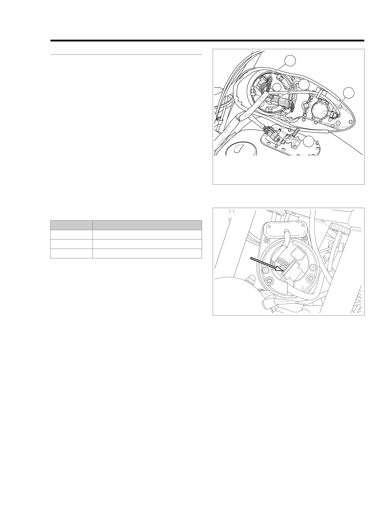
1. Speedometer [39]
voltage is greater than 16.0V for longer than 5 seconds.
2. Indicator lamps [21]
3. Ignition switch [33]
NOTE
4. Fuel pump and sender [141]
ECM, ABS, ECU and/or BCM may also set a battery voltage
Figure 3-20. Under Console: Except FXS/B
DTC.
Table 3-32. Code Description
ed03299
DTC
DESCRIPTION
B2271
BCM voltage low
B2272
BCM voltage high
B2272
Speedometer voltage high
Figure 3-21. Speedometer [39]: FXS/B Typical
Diagnostic Tips
High voltage DTC may set when the vehicle is placed on an
unapproved constant current battery charger, on fast charge,
for a long period of time.
Connector Information
For additional information about the connectors in the following
diagram(s) and diagnostic procedure(s), including the color of
the harness test kit terminal probes, see B.1 CONNECTORS.
2013 Softail Diagnostics: Starting and Charging 3-35