Harley Davidson Softail Delux FLSTN BIKE 2011-2015. Electrical Diagnostics - page 4
HOME
2. Is battery voltage present?
2. Is continuity present?
a. Yes. Go to Test 3.
a. Yes. Go to Test 3.
b. No. Repair open in (BK/GN) wire.
b. No. Repair open in (W/R) wire.
3. CAN High Circuit Continuity Test
4. CAN Low Circuit Continuity Test
1. Test continuity between [24A] terminal 3 and DLC [91A]
1. Test continuity between [22A-1] terminal 4 and [91A] ter-
terminal 1.
minal 3.
2. Is continuity present?
2. Is continuity present?
a. Yes. Go to Test 4.
a. Yes. Replace the RHCM.
b. No. Repair open in (W/R) wire.
b. No. Repair open in (W/BK) wire.
4. CAN Low Circuit Continuity Test
SPEEDOMETER INOPERATIVE: DTC U0156
1. Test continuity between [24A] terminal 4 and [91A] terminal
3.
PART NUMBER
TOOL NAME
HD-41404
HARNESS CONNECTOR TEST KIT
2. Is continuity present?
HD-42682
BREAKOUT BOX
a. Yes. Replace the LHCM.
HD-46601
BREAKOUT BOX ADAPTERS
b. No. Repair open in (W/BK) wire.
DTC U0142
Table 2-11. DTC U0156 Diagnostic Faults
PART NUMBER
TOOL NAME
POSSIBLE CAUSES
HD-41404
HARNESS CONNECTOR TEST KIT
Open in CAN high circuit to the speedometer
Open in CAN low circuit to the speedometer
Open in speedometer battery power circuit
Table 2-10. DTC U0142 Diagnostic Faults
Open in speedometer ground circuit
POSSIBLE CAUSES
Open in CAN high circuit to the RHCM
1. Speedometer Voltage Test
Open in CAN low circuit to the RHCM
1. Turn IGN OFF.
Open in RHCM battery power circuit
2. Connect BREAKOUT BOX (Part No. HD-42682) and
Open in RHCM ground circuit
BREAKOUT BOX ADAPTERS (Part No. HD-46601) to
the wiring harness [39B], leaving the [39A] disconnected.
1. Fuse Test
3. Using HARNESS CONNECTOR TEST KIT (Part No. HD-
1. Check battery fuse.
41404), test voltage between BOB terminal 5 and ground.
2. Is fuse good?
4. Is battery voltage present?
a. Yes. Go to Test 2.
a. Yes. Go to Test 2.
b. No. Repair as needed, replace fuse.
b. No. Repair open in (R/O) wire.
2. RHCM Voltage Test
2. Speedometer Ground Test
1. Turn IGN OFF.
1. Test voltage between BOB terminals 5 and 7.
2. Disconnect LHCM [24A].
2. Is battery voltage present?
a. Yes. Go to Test 3.
3. Using HARNESS CONNECTOR TEST KIT (Part No. HD-
41404), test voltage between RHCM [22A-1] terminal 1
b. No. Repair open in (BK/GN) wire.
and ground.
3. CAN High Circuit Continuity Test
4. Is battery voltage present?
a. Yes. Go to Test 2.
1. Test continuity between BOB terminal 2 and DLC [91A]
terminal 1.
b. No. Repair open in (R/O) wire.
2. Is continuity present?
3. CAN High Circuit Continuity Test
a. Yes. Go to Test 4.
1. Test continuity between [22A-1] terminal 3 and DLC [91A]
b. No. Repair open in (W/R) wire.
terminal 1.
2-26 2013 Softail Diagnostics: Initial Diagnostics and Serial Data
HOME
2. Is continuity present?
4. CAN Low Circuit Continuity Test
a. Yes. Replace speedometer.
1. Test continuity between BOB terminal 8 and [91A] terminal
3.
b. No. Repair open in (W/BK) wire.
2013 Softail Diagnostics: Initial Diagnostics and Serial Data 2-27
NOTES
2-28 2013 Softail Diagnostics: Initial Diagnostics and Serial Data
TABLE OF CONTENTS
SUBJECT
PAGE NO.
3.1 BATTERY TESTING
3-1
3.2 STARTING SYSTEM
3-3
3.3 DTC B2121, B2122, B2123, B2124
3-11
3.4 TESTING STARTER ON MOTORCYCLE
3-14
3.5 TESTING STARTER ON BENCH
3-15
3.6 CHARGING SYSTEM
3-17
3.7 DTC C0562, C0563, C1222, C1223
3-22
3.8 DTC P0562
3-26
3.9 DTC B2203
3-30
3.10 DTC B2206, B2208
3-33
3.11 DTC B2271, B2272
3-35
NOTES
HOME
BATTERY TESTING
3.1
GENERAL
ed03289
Test battery condition by using a voltage, charging or load test.
Always fully charge battery prior to load testing.
NOTE
An automatic, constant monitoring battery charger/tender with
a charging rate of 5 Amps or less at less than 14.6V is recom-
mended. The use of constant current chargers (including trickle
chargers) to charge sealed AGM batteries is not recommended.
Any overcharge will cause dry-out and premature battery
failure.
VOLTMETER TEST
The voltmeter test provides a general indication of battery state
of charge or condition. Check the voltage of the battery to verify
that it is in a 100% fully charged condition. Refer to Table 3-1.
If the open circuit (disconnected) voltage reading is below
12.6V, charge the battery and then recheck the voltage after
the battery has set for one to two hours. If the voltage reading
is
12.7V or above, perform a load test. See 3.1 BATTERY
TESTING, Load Test.
Table 3-1. Voltmeter Test For Battery Charge Conditions
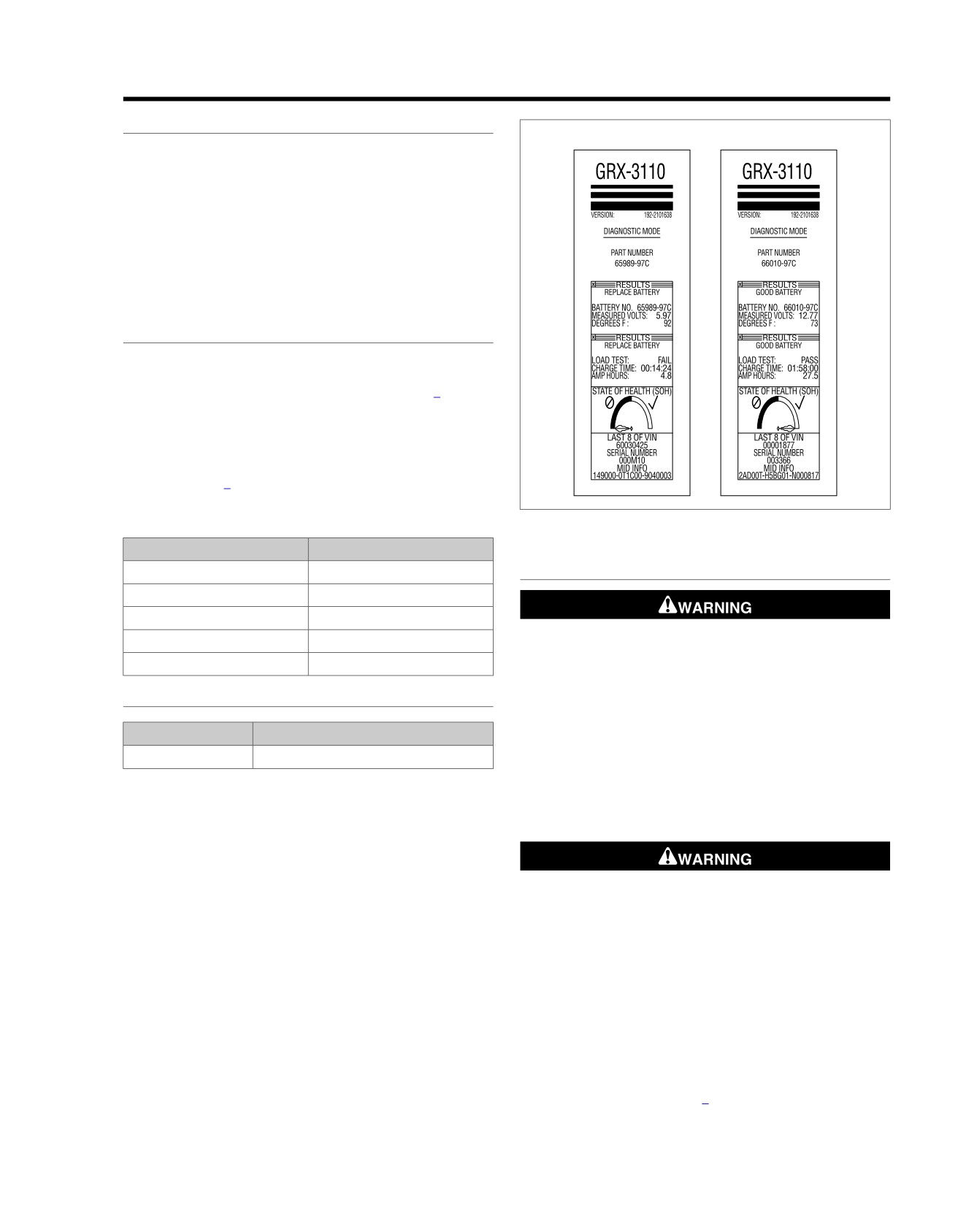
Figure 3-1. Battery Test Results Printout (Typical)
VOLTAGE
STATE OF CHARGE
12.7
100%
LOAD TEST
12.6
75%
12.3
50%
12.0
25%
Disconnect negative (-) battery cable first. If positive (+)
cable should contact ground with negative (-) cable con-
11.8
0%
nected, the resulting sparks can cause a battery explosion,
which could result in death or serious injury. (00049a)
BATTERY DIAGNOSTIC TEST
1. With vehicle battery on a bench, charge the battery using
an automatic, self monitoring battery charger approved
PART NUMBER
TOOL NAME
for AGM batteries.
GRX-3110 HD
BATTERY DIAGNOSTIC STATION
NOTE
Test the battery using the GRX.
Always fully charge the battery before testing or test readings
will be incorrect. Load testing a discharged battery can also
1. Disconnect and remove battery.
result in permanent battery damage.
2. Connect the BATTERY DIAGNOSTIC STATION (Part
No. GRX-3110 HD) leads to the battery terminal.
3. Read the GRX instruction manual before performing a
Turn battery load tester OFF before connecting tester
battery test.
cables to battery terminals. Connecting tester cables with
load tester ON can cause a spark and battery explosion,
The test results will include a decision on the battery condition
which could result in death or serious injury. (00252a)
and the measured state of charge. See Figure 3-1. The GRX
printer will provide a printout including the test results:
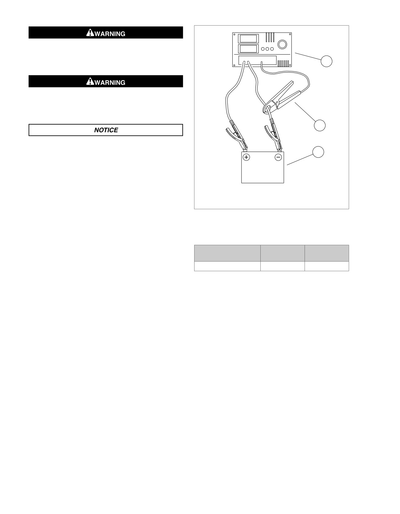
2. See Figure 3-2. Connect tester leads to battery posts and
place induction pickup over negative (black) cable.
•
GOOD BATTERY - Return the battery to service.
NOTE
•
REPLACE BATTERY - Replace the battery.
To avoid load tester and/or battery damage, do not leave the
load tester switch turned ON for more than 20 seconds.
3. Load battery at 50% of CCA rating using the load tester.
Voltage reading after 15 seconds should be 9.6V or more
at 70 °F (21 °C). Refer to Table 3-2.
2013 Softail Diagnostics: Starting and Charging 3-1
HOME
ed02812
VOLTS
Turn battery load tester OFF before disconnecting tester
AMPS
cables to battery terminals. Disconnecting tester cables
with load tester ON can cause a spark and battery explo-
1
sion, which could result in death or serious injury. (00253a)
Connect positive (+) battery cable first. If positive (+) cable
should contact ground with negative (-) cable connected,
the resulting sparks can cause a battery explosion, which
could result in death or serious injury. (00068a)
2
Do not over-tighten bolts on battery terminals. Use
recommended torque values. Over-tightening battery ter-
3
minal bolts could result in damage to battery terminals.
(00216a)
1. Load tester
2. Induction pickup
3. Battery
Figure 3-2. Load Test Battery
Table 3-2. Battery Load Test
COLD CRANKING
100%
50%
AMPERAGE (CCA)
Softail models
315
155
3-2 2013 Softail Diagnostics: Starting and Charging
HOME
STARTING SYSTEM
3.2
DESCRIPTION AND OPERATION
ed03465
Battery voltage is supplied to the BCM at all times through the
2
3
main fuse. The BCM provides and monitors a voltage signal
2
to the ignition switch. This signal changes depending on the
position of the IGN switch.
1
When the engine stop switch is in the RUN position, a CAN
message is sent, signaling the BCM that the switch is in the
RUN position. If CAN communication is interrupted while the
engine is running, the BCM checks for the signal from the
redundant engine stop switch circuit.
When the start switch is pressed, a CAN message is sent to
the BCM. The BCM provides power to the starter solenoid.
This energizes the solenoid and full battery power is sent to
the starter. The BCM disables the starter solenoid if the start
4
switch is pressed for more than 10 seconds.
COMPONENTS
5
Starter
6
The starter receives power from the battery through the starter
solenoid and is grounded through the starter case. When the
starter solenoid is energized, two events happen:
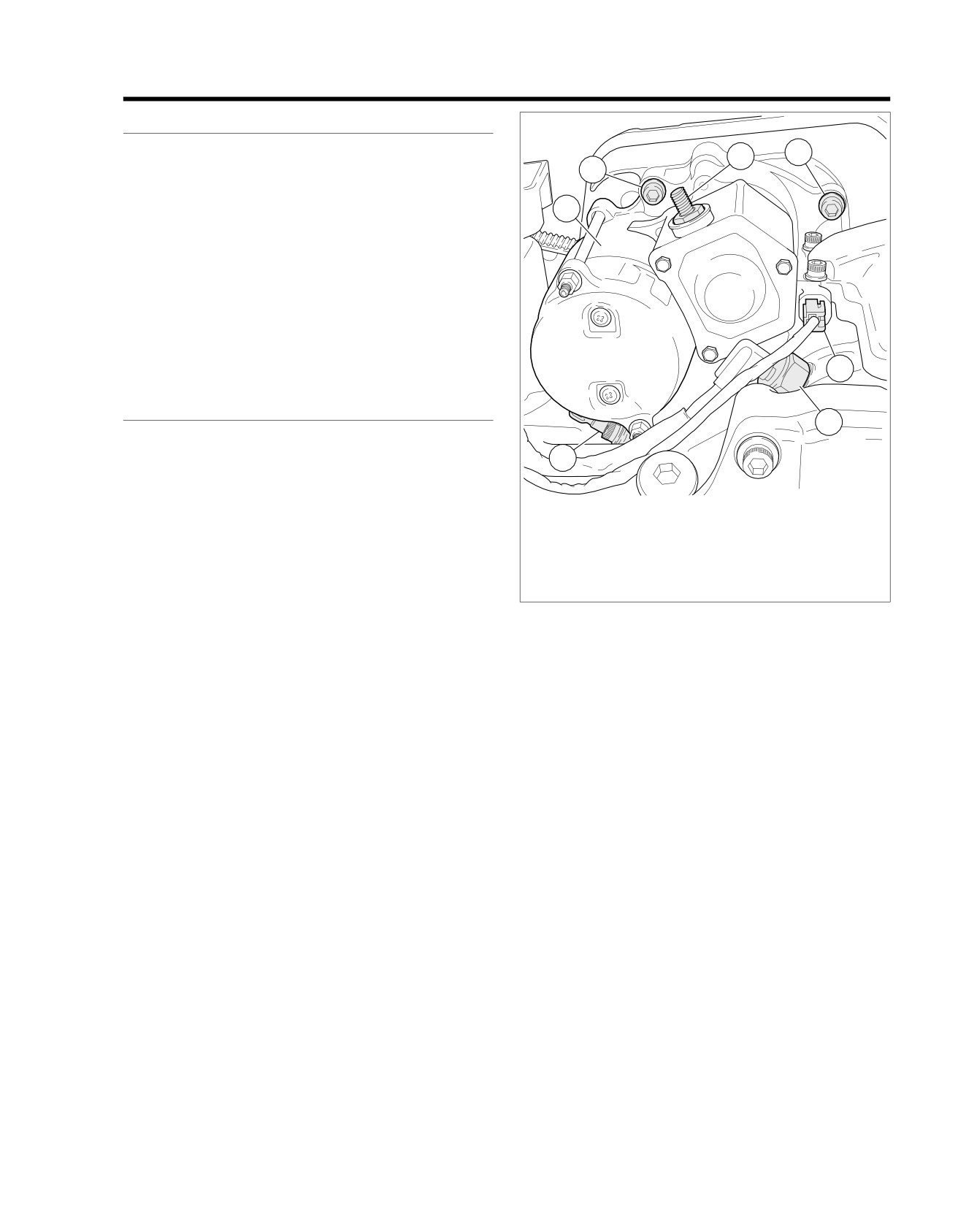
1. Starter
•
The plunger pulls inward which allows current to flow to
2. Starter mounting fasteners
the starter motor.
3. Positive battery cable post
4. Solenoid wire
•
The pinion gear engages with the ring gear on the clutch
5. Neutral switch
shell.
6. Vehicle speed sensor
With the starter motor turning, the rotation is transferred:
Figure 3-3. Starter
•
The starter armature gear transfers rotation to the idler
gear.
Starter Solenoid
•
The idler gear transfers rotation to the starter clutch.
See Figure 3-3. The starter solenoid provides power to the
•
The starter clutch transfers rotation through a spline gear
starter. The solenoid is a means of controlling a high amperage
to the starter drive shaft which also drives the pinion gear.
device with a low amperage switch. The low amperage switch
•
The pinion gear transfers its rotation to the ring gear on
in this circuit is the BCM. The BCM sends voltage to the starter
the clutch shell.
solenoid making a magnetic field that pulls a larger circuit
closed, allowing voltage to the starter.
•
The primary chain drives the alternator rotor sprocket on
the end of the crankshaft.
Engine Stop Switch
The starter clutch has a one-way clutch. When the engine
The engine stop switch is located on the right hand controls.
starts, it allows the clutch shell and sprocket to spin freely
With the engine stop switch in the RUN position, a CAN mes-
without causing any damage to the starter motor. After the
sage is sent, signaling the BCM that the switch is in the RUN
engine starts and the start switch is released, the plunger
position. If CAN communication is interrupted while engine is
returns to its normal position, disengaging the pinion gear from
running, a redundant engine stop switch circuit allows commu-
the clutch shell and sprocket.
nication to the BCM.
Start Switch
The start switch is a push button switch located in the right
hand controls. When the start switch is pressed, a CAN mes-
sage is sent to the BCM.
BCM
The BCM supplies ignition and accessory power to most of the
vehicle. It controls the lighting along with other functions on
the vehicle by using the switches as inputs and the power cir-
cuits for the lights and other electrical loads as outputs.
2013 Softail Diagnostics: Starting and Charging 3-3
HOME
Ignition Switch
The BCM provides and monitors a voltage signal to the ignition
switch, which is an open circuit in the OFF position. The ignition
If battery releases an excessive amount of gas during
switch routes the signal through a 200 Ohm resistor to ground
charging, decrease the charging rate. Overheating can
in the IGN position or through a 800 Ohm resistor to ground in
result in plate distortion, internal shorting, drying out or
the ACC position. The difference in resistance in the ignition
damage. (00413b)
switch informs the BCM of the switch position.
The AGM batteries are permanently sealed, maintenance-free,
valve-regulated, lead/calcium and sulfuric acid batteries.
Battery
The battery is recharged by the alternator and kept from over-
charging by the regulator during use.
Battery condition can be determined by a voltage test, a char-
Batteries contain sulfuric acid, which could cause severe
ging and a load test. See 3.1 BATTERY TESTING.
burns to eyes and skin. Wear a protective face shield,
rubberized gloves and protective clothing when working
The battery must be fully charged to perform a conductance
with batteries. KEEP BATTERIES AWAY FROM CHILDREN.
test or a load test.
(00063a)
Grinding Noise or Erratic Starting
1. Remove starter.
2. Inspect the starter mounting surface and mating area on
Never remove warning label attached to top of battery.
inner primary for arcing and pitting. This condition is
Failure to read and understand all precautions contained
caused by insufficient ground and or clamp load.
in warning, could result in death or serious injury. (00064a)
3. Clean mating surfaces.
4. Inspect starter pinion gear. Replace starter clutch assem-
Explosive hydrogen gas, which escapes during charging,
blies with cracked or missing teeth. Rounding of pinion
could cause death or serious injury. Charge battery in a
gear teeth is considered normal. If replacing pinion gear,
well-ventilated area. Keep open flames, electrical sparks
inspect ring gear on clutch. Replace clutch ring gear if
and smoking materials away from battery at all times.
damaged.
KEEP BATTERIES AWAY FROM CHILDREN. (00065a)
5. Install starter.
Job/Time Code Values
Dealership Technicians filing warranty claims should use the
If battery becomes hot, gassing or spewing of electrolyte
job/time code values printed in (bold text) beside the appro-
can occur, which could cause death or serious injury.
priate repair.
Unplug or turn OFF the charger until battery cools.
(00412b)
Connector Information
For additional information about the connectors in the following
diagram(s) and diagnostic procedure(s), including the color of
the harness test kit terminal probes, see B.1 CONNECTORS.
Batteries, battery posts, terminals and related accessories
contain lead and lead compounds, and other chemicals
known to the State of California to cause cancer, and birth
defects or other reproductive harm. Wash hands after
handling. (00019e)
3-4 2013 Softail Diagnostics: Starting and Charging
HOME
em01518
Fuse
2
B
Block
BK
R
Battery
Main
15A
40A
1
A
Battery
[64B]
1
GND 1
[128B]
R/BK
[259B] [259A]
2
BCM
Starter
R
1
1
Battery Power
R/BK
L2
L2
Starter Solenoid Power
W/BE
C3
C3
Ignition Switch Input
Ignition
Switch
W
D3
D3
Neutral Switch Input
BCM Input
2
2
W/BE
5
5
W/BE
W/R
D2
D2
CAN High
(ExceptFXS/B)
Ground
1
1
BK/GN
2
2
BK/GN
W/BK
E2
E2
CAN Low
W/BE
BK/GN
G4
G4
Ground
[33A] [33B]
[20B] [20A]
BK/GN
W/GY
C4
C4
Engine Stop Switch Input
Ignition
Switch
BCM Input
2
2
W/BE
W/BE
[242B] [242A]
(FXS/B)
Ground
1
1
BK/GN
BK/GN
[22A-1] [22B-1]
[33A] [33B]
W/BK
4
4
W/BK
CAN Low
W/R
3
3
W/R
CAN High
Right
BK/GN
2
2
BK
Ground
Hand
R/O
1
1
R/O
Battery
Controls
Neutral
[131A-1] [131B-1]
Switch
W/GY
1
1
W/GY
Engine Stop Switch
BCM Input
1
1
W
[22A-2] [22B-2]
Ground
1
1
BK
[131A-2] [131B-2]
R/O
1
1
R/O
Battery
BK/GN
2
2
BK
Ground
Left
Hand
W/R
3
3
W/R
CAN High
Controls
W/BK
4
4
W/BK
CAN Low
[24A] [24B]
ACR
System Power
1
1
R/GN
ACR
2
2
LGN/R
GND 2
GND 1
ECM
[203FA]
[203FB]
R/O
18
18
Battery Fuse
BK/GN
10
10
Ground
ACR
System Power
1
1
R/GN
R/GN
16
16
System Power
ACR
2
2
LGN/R
LGN/R
4
4
ACR ENABLE
[203RA] [203RB]
[78B-2] [78A-2]
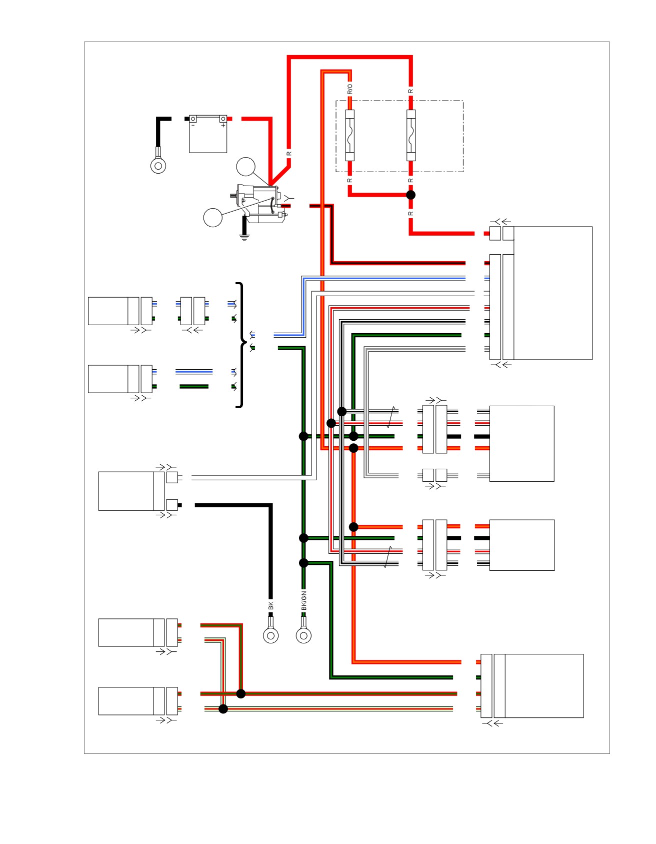
Figure 3-4. Starting Circuit
2013 Softail Diagnostics: Starting and Charging 3-5
HOME
gnose starting system problems. The 1.3 DIAGNOSTICS AND
STARTER TROUBLESHOOTING
TROUBLESHOOTING, Voltage Drop procedure will help you
The troubleshooting tables contain detailed procedures to solve
to locate poor connections or components with excessive
and correct problems. Follow 3.2 STARTING SYSTEM to dia-
voltage drops.
Table 3-3. Starter Does Not Run or Runs at Very Low Speeds
SOURCE OF PROBLEM
POSSIBLE CAUSE
SOLUTION
Battery
Voltage drop due to discharged battery.
Charge battery.
Short-circuit or open between electrodes.
Replace battery.
Poor contact condition of battery ter-
Clean and retighten.
minal(s).
Wiring
Poor or no connection at either end of the
Repair or replace cable(s).
battery positive or negative cable.
Cracked or corroded battery cable ends.
Clean, tighten or replace cable(s) as
needed.
Open wire(s) or poor connection at
Tighten connections or repair or replace
handlebar switch or BCM ground wire.
wire(s).
Start switch or engine stop switch
Stuck switch or open switch.
Replace RHCM.
Neutral switch
Switch or wiring from neutral switch to
Replace neutral switch or repair open.
BCM failed open.
Clutch switch
Clutch switch always open.
Replace clutch switch.
Starter solenoid
Poor contact condition caused by burned
Replace solenoid assembly.
contacts.
Windings open or short-circuited.
Replace solenoid assembly.
Starter motor
Brushes worn below specification.
Replace starter.
Commutator burnt.
Replace starter.
Commutator high mica.
Replace starter.
Field winding grounded.
Replace starter.
Armature winding grounded or short-cir-
Replace starter.
cuited.
Free running current draw out of range.
Replace starter.
Insufficient brush spring tension.
Replace starter.
ACR (if equipped)
ACR failure.
Replace ACR.
Starter clutch
Starter clutch failure.
Replace starter clutch assembly.
Table 3-4. Starter Spins But Does Not Engage
SOURCE OF PROBLEM
POSSIBLE CAUSE
SOLUTION
Battery
Voltage drop due to discharged battery.
Charge battery.
Short-circuit or open between electrodes.
Replace battery.
Poor contact condition of battery ter-
Clean and retighten.
minal(s).
Starter motor
Pinion gear teeth worn out.
Replace starter clutch assembly.
Gear teeth on clutch shell and sprocket.
Excessively worn teeth.
Replace clutch shell and sprocket.
Starter clutch
Starter clutch failure.
Replace starter clutch assembly.
3-6 2013 Softail Diagnostics: Starting and Charging
HOME
Table 3-5. Starter Does Not Stop Running
SOURCE OF PROBLEM
POSSIBLE CAUSE
SOLUTION
Starter solenoid
Coil shorted.
Replace starter solenoid assembly.
Contact plate melted and stuck.
Replace starter solenoid assembly.
STARTER TESTING
NOTHING CLICKS
Table 3-6. Starter Testing Diagnostic Faults
PART NUMBER
TOOL NAME
HD-41404
HARNESS CONNECTOR TEST KIT
POSSIBLE CAUSES
HD-50390-1
BREAKOUT BOX
Short to voltage at starter solenoid
HD-50390-2
BCM CABLE
Start switch malfunction
HD-50390-2-P
BCM OVERLAY
Short to voltage on BCM supply circuit
1. Starting System Operational Test
Table 3-7. Nothing Clicks Diagnostic Faults
1. With IGN ON, transmission in neutral and the engine stop
switch in the RUN position, press the start switch.
POSSIBLE CAUSES
Low battery
2. Does the starter spin?
Open fuse
a. Yes, starter spins but does not engage. See
3.2 STARTING SYSTEM, Starter Spins But Does Not
Neutral switch malfunction
Engage.
Open neutral circuit
b. Yes, starter stalls or spins too slowly. See
Ignition switch malfunction
3.2 STARTING SYSTEM, Starter Stalls or Spins Too
Open ignition circuit
Slowly.
c. Yes, starter runs on. Go to Test 3.
NOTE
d. No. Go to Test 2.
Verify that vehicle is in neutral. Check that the key fob is
present and in working order (if security equipped). Verify the
2. Audible Noise Test
engine stop switch is in RUN position.
1. While listening for audible clicking noise from the starter
1. Battery Test
solenoid, press the start switch.
1. Perform a battery test. See 3.1 BATTERY TESTING.
2. Is there a click?
2. Did battery pass test?
a. Yes, starter solenoid clicks. See 3.2 STARTING
SYSTEM, Starter Solenoid Clicks.
a. Yes. Go to Test 2.
b. No. See 3.2 STARTING SYSTEM, Nothing Clicks.
b. No. Replace battery.
2. Fuse Test
3. Starter Solenoid Test
1. Verify all fuses are good.
1. Disconnect starter solenoid [128].
2. Are fuses good?
2. Does starter stop?
a. Yes. Go to Test 3.
a. Yes. Go to Test 4.
b. No. Replace fuse and repair circuit accordingly. If
b. No. Replace starter solenoid assembly. (5845)
problem is still present, then continue tests. Go to
Test 3.
4. Checking DTCs Test
1. Check for DTCs.
3. Ignition Circuit Test
2. Is DTC B2122 present?
1. Turn IGN ON.
a. Yes. See 3.3 DTC B2121, B2122, B2123, B2124.
b. No. Replace BCM. (5838)
2013 Softail Diagnostics: Starting and Charging 3-7
HOME
2. Do odometer, headlamp and tail lamps illuminate?
5. Is continuity present?
a. Yes. Go to Test 4.
a. Yes. Go to Test 8.
b. No. Odometer is inoperative, but headlamp and
b. No. Repair open in (W) wire. (5041)
tail lamps illuminate. See 2.3 ODOMETER SELF-
DIAGNOSTIC INOPERATIVE, DTC U0001, U0011,
8. BCM Test
B2274.
1. Turn IGN OFF, turn engine stop switch to OFF.
c. No. Odometer, headlamp and tail lamps
2. Disconnect BCM and replace with known good BCM.
inoperative. See 2.4 NO VEHICLE POWER OR DTC
U0100, U0121, U0140, U0141, U0142, U0156, No
3. Turn IGN ON.
Vehicle Power: DTC U0140.
4. Turn engine stop switch to RUN, attempt to start vehicle.
4. Starter Solenoid Circuit Test
5. Does engine crank?
1. Turn IGN OFF.
a. Yes. Replace BCM. (5838)
2. Disconnect starter solenoid [128].
b. No. Replace RHCM. (6166)
3. Turn IGN ON.
STARTER SOLENOID CLICKS
4. Using HARNESS CONNECTOR TEST KIT (Part No. HD-
41404), test voltage at [128B] (R/BK) wire during the first
Table 3-8. Starter Solenoid Clicks Diagnostic Faults
4-5 seconds, while start button is pressed.
POSSIBLE CAUSES
5. Is battery voltage present?
Low battery
a. Yes. Go to Test 5.
Starter malfunction
b. No. Go to Test 6.
Starter solenoid malfunction
5. Starter Ground Test
Open battery cable
1. Remove starter attaching bolts.
Open starter cable
Mechanical binding
2. Clean bolts and starter base, install starter bolts.
3. Does engine crank?
1. Battery Test
a. Yes. Engine cranks at normal speed. Repair com-
1. Perform battery test. See 3.1 BATTERY TESTING.
plete. (5817)
2. Did battery pass test?
b. Yes. Engine cranks, but at a slower speed. See
a. Yes. Go to Test 2.
3.4 TESTING STARTER ON MOTORCYCLE, Starter
Current Draw Test.
b. No. Replace battery.
c. No. Replace starter solenoid. (5845)
2. Starter Voltage Drop Test
6. Neutral Switch Test
1. Perform voltage drop tests from battery (+) to starter stud
on starter
(BK) wire. See
1.3 DIAGNOSTICS AND
1. With IGN ON and the transmission in neutral, observe the
TROUBLESHOOTING, Voltage Drop.
neutral lamp.
2. Is voltage drop greater than 1.0V?
2. Is the neutral lamp illuminated?
a. Yes. Go to Test 3.
a. Yes. Go to Test 7.
b. No. Go to Test 5.
b. No. See 4.5 INDICATOR LAMPS, Neutral Lamp
Inoperative.
3. Starter Solenoid Voltage Drop Starter Side
7. Starter Solenoid Circuit Test
Test
1. Turn IGN OFF.
1. Perform voltage drop test from battery (+) terminal to
starter solenoid terminal 2 (BK) wire.
2. Connect the BREAKOUT BOX (Part No. HD-50390-1) and
BCM CABLE (Part No. HD-50390-2) between wire harness
2. Is voltage drop greater than 1.0V?
[242B] and BCM [242A]. See 1.2 DIAGNOSTIC TOOLS.
a. Yes. Go to Test 4.
3. Verify BCM OVERLAY (Part No. HD-50390-2-P) is in
b. No. Replace starter solenoid assembly. (5845)
position on BOB.
4. Starter Solenoid Battery Side Voltage
4. Test continuity between BOB terminal L2 and [128B].
Drop Test
1. Perform voltage drop test from battery (+) terminal to
starter solenoid terminal 1 (BK) wire.
3-8 2013 Softail Diagnostics: Starting and Charging
HOME
2. Is voltage drop greater than 1.0V?
STARTER SPINS BUT DOES NOT ENGAGE
a. Yes. Repair or replace (BK) wire from starter solenoid
terminal 1 to battery (+) terminal. (5041)
Table 3-9. Starter Spins But Does Not Engage Diagnostic
b. No. Replace starter solenoid assembly. (5845)
Faults
POSSIBLE CAUSES
5. Starter Ground Circuit Voltage Drop Test
Clutch assembly
1. Perform voltage drop test from battery (-) terminal to
Clutch shell and sprocket
ground.
2. Is voltage drop greater than 1.0V?
1. Pinion Gear and Clutch Shell Test
a. Yes. Inspect (BK) wire for damage from battery (-)
1. Remove primary cover.
terminal to chassis ground, repair or replace if
necessary. Go to Test 6.
2. Inspect for damage to starter pinion gear and clutch shell
and sprocket.
b. No. Go to Test 7.
NOTE
6. Starter Ground Test
Inspect ACR operation (if equipped) before installation of new
starter clutch assembly.
1. Remove starter attaching bolts.
3. Is damage present?
2. Clean bolts and starter base, install starter bolts.
a. Yes. Replace the clutch assembly or clutch shell and
3. Does engine crank?
sprocket. (5825)
a. Yes. Engine cranks at normal speed. Repair com-
b. No. Replace the clutch assembly. (5837)
plete.
b. Yes. Engine cranks, but at a slower speed. See
STARTER STALLS OR SPINS TOO SLOWLY
3.4 TESTING STARTER ON MOTORCYCLE, Starter
Current Draw Test.
PART NUMBER
TOOL NAME
c. No. Replace starter. (5817)
HD-41404
HARNESS CONNECTOR TEST KIT
HD-50390-1
BREAKOUT BOX
7. Starter Draw Test
HD-50390-4
ECM CABLE
1. Perform Starter Current Draw Test on motorcycle. See
HD-50390-4-P
ECM OVERLAY
3.4 TESTING STARTER ON MOTORCYCLE, Starter
Current Draw Test.
2. Perform Starter Motor Free Running Current Draw Test
Table 3-10. Starter Stalls or Spins Too Slowly Diagnostic
(on bench). See 3.5 TESTING STARTER ON BENCH,
Faults
Free Running Current Draw Test.
POSSIBLE CAUSES
3. Are test results within range?
Low battery
a. Yes. Go to Test 8.
Starter malfunction
b. No. Replace starter. (5817)
Starter solenoid malfunction
Poor connections at starter ground
8. Mechanical Binding Test
Open battery cable
1. Remove spark plugs and place transmission in 5th gear.
Open starter cable
2. Raise vehicle.
ACR malfunction (if equipped)
3. Rotate rear wheel.
1. Battery Test
4. Check for engine binding in the primary and/or crankshaft
or starter clutch.
1. Perform battery test. See 3.1 BATTERY TESTING.
5. Is engine binding?
2. Did battery pass test?
a. Yes. Repair as needed. (Use appropriate code).
a. Yes. Go to Test 2.
b. No. Replace starter solenoid assembly. (5845)
b. No. Replace battery.
2. Starter Stud Voltage Drop Test
1. Perform voltage drop test from battery (+) terminal to
starter stud on starter (BK) wire. See 1.3 DIAGNOSTICS
AND TROUBLESHOOTING, Voltage Drop.
2013 Softail Diagnostics: Starting and Charging 3-9
HOME
2. Is voltage drop greater than 1.0V?
2. Perform Starter Motor Free Running Current Draw Test
(on bench). See 3.5 TESTING STARTER ON BENCH,
a. Yes. Go to Test 5.
Free Running Current Draw Test.
b. No. Go to Test 3.
3. Are test results within range?
3. Starter Ground Circuit Voltage Drop Test
a. Yes. With the spark plugs removed and the transmis-
sion in 5th gear, rotate rear wheel. Check for engine,
1. Perform voltage drop test between battery (-) terminal and
primary and/or crankshaft bind. (Use appropriate
starter attaching bolts.
code)
2. Is voltage drop greater than 1.0V?
b. No. Replace starter. (5817)
a. Yes. Clean ground connections. (5041)
6. Starter Solenoid Voltage Drop Starter Side
b. No. Go to Test 4.
Test
4. ACR Test
1. Perform voltage drop test between battery (+) terminal to
1. Turn IGN OFF.
starter solenoid terminal 2.
2. Connect BREAKOUT BOX (Part No. HD-50390-1) and
2. Is voltage drop greater than 1.0V?
ECM CABLE (Part No. HD-50390-4) between wire harness
a. Yes. Go to Test 7.
[78B-1],
[78B-2] and
[78A-1],
[78A-2]. See
1.2 DIA-
GNOSTIC TOOLS.
b. No. Repair connection or (BK) wire between starter
solenoid and starter. (5041)
3. Verify ECM OVERLAY (Part No. HD-50390-4-P) is in
position on BOB.
7. Starter Solenoid Battery Side Voltage
4. Turn IGN ON.
Drop Test
5. Using HARNESS CONNECTOR TEST KIT (Part No. HD-
1. Perform voltage drop test between battery (+) terminal
41404), jumper between BOB [78-2] terminal 16 and ter-
and starter solenoid terminal 1 (R) wire.
minal 18.
2. Is voltage drop greater than 1.0V?
6. Jumper between BOB [78-2] terminal 4 and terminal 10.
a. Yes. Repair or replace connection between battery
(+) terminal and starter solenoid terminal 1 (R) wire.
7. Does ACR's click?
(5041)
a. Yes. Go to Test 5.
b. No. Repair or replace starter solenoid assembly.
b. No. Replace front and rear ACR solenoids.
(5845)
5. Starter Draw Test
1. Perform Starter Current Draw Test on motorcycle. See
3.4 TESTING STARTER ON MOTORCYCLE, Starter
Current Draw Test.
3-10 2013 Softail Diagnostics: Starting and Charging
HOME
DTC B2121,
B2122, B2123, B2124
3.3
DESCRIPTION AND OPERATION
Conditions for Setting
The starter solenoid circuit is controlled and monitored by the
DTC B2121 will set if the starter solenoid circuit draws less
BCM. The BCM receives a CAN message from the start switch
than 600 milliamps. DTC B2124 will set if the starter solenoid
in the RHCM to engage the starter. Voltage is sent from the
circuit draws more than 12 Amps.
BCM to the starter solenoid [128] (R/BK) wire. The BCM dis-
Connector Information
ables the starter solenoid if the start switch is pressed for more
than 10 seconds.
For additional information about the connectors in the following
diagram(s) and diagnostic procedure(s), including the color of
the harness test kit terminal probes, see B.1 CONNECTORS.
Table 3-11. Code Description
DTC
DESCRIPTION
B2121
Starter output open
B2122
Starter output shorted high
B2123
Starter output shorted low
B2124
Starter output overloaded
em00873
Fuse
2
B
Block
BK
R
Battery
Main
15A
40A
1
A
Battery
[64B]
1
GND 1
[128B]
R/BK
[259B] [259A]
2
BCM
Starter
R
1
1
Battery Power
R/BK
L2
L2
Starter Solenoid Power
W/R
D2
D2
CAN High
W/BK
E2
E2
CAN Low
[22B-1] [22A-1]
BK/GN
G4
G4
Ground
CAN Low
W/BK
4
4
W/BK
W/GY
C4
C4
Engine Stop Switch Input
CAN High
W/R
3
3
W/R
Right
Ground
BK
2
2
BK/GN
Hand
[242B] [242A]
Controls
Battery
R/O
1
1
R/O
Engine Stop Switch
W/GY
1
1
W/GY
[22B-2] [22A-2]
GND 1
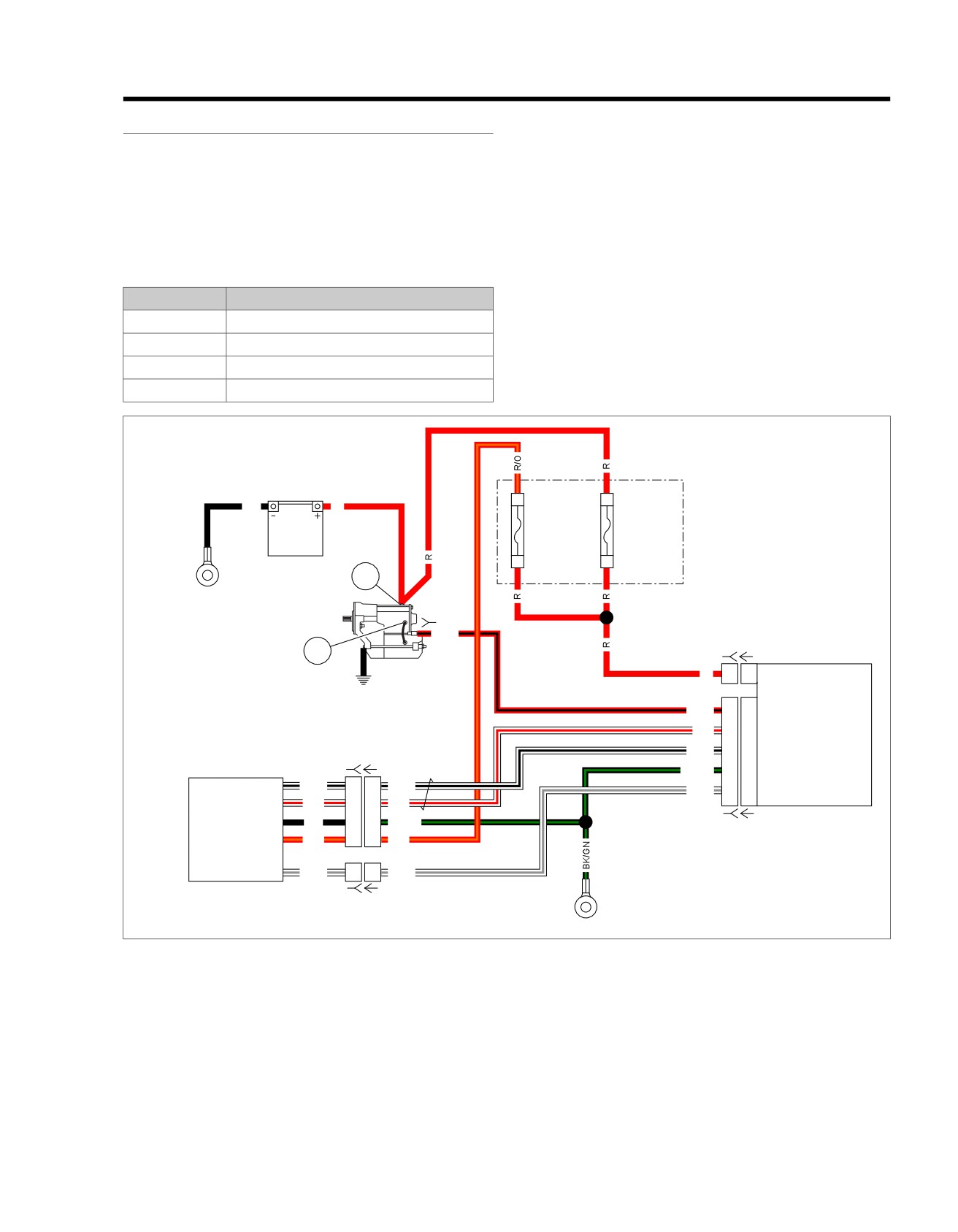
Figure 3-5. Starter
2013 Softail Diagnostics: Starting and Charging 3-11
HOME
DTC B2121
DTC B2122
PART NUMBER
TOOL NAME
PART NUMBER
TOOL NAME
HD-41404
HARNESS CONNECTOR TEST KIT
HD-41404
HARNESS CONNECTOR TEST KIT
HD-50390-1
BREAKOUT BOX
HD-50390-1
BREAKOUT BOX
HD-50390-2
BCM CABLE
HD-50390-2
BCM CABLE
HD-50390-2-P
BCM OVERLAY
HD-50390-2-P
BCM OVERLAY
Table 3-12. DTC B2121 Diagnostic Faults
Table 3-13. DTC B2122 Diagnostic Faults
POSSIBLE CAUSES
POSSIBLE CAUSES
Open in starter circuit
Short in starter circuit
Open in starter solenoid
Short in starter solenoid
1. Starter Solenoid Circuit Test
1. Starter Solenoid Circuit Test
1. Turn IGN OFF.
1. Turn IGN OFF.
2. Disconnect starter solenoid [128].
2. Disconnect starter solenoid [128].
3. With IGN ON, using HARNESS CONNECTOR TEST KIT
3. With IGN ON, using HARNESS CONNECTOR TEST KIT
(Part No. HD-41404), test for battery voltage at [128B]
(Part No. HD-41404), test voltage at [128B] (R/BK).
(R/BK) during the first 4-5 seconds while start button is
4. Is battery voltage present?
pressed.
a. Yes. Go to Test 2.
4. Is battery voltage present?
b. No. Replace starter solenoid assembly. (5845)
a. Yes. Replace starter solenoid assembly. (5845)
b. No. Go to Test 2.
2. Starter Solenoid Supply Voltage Test
1. Turn IGN OFF.
2. Starter Solenoid Supply Voltage Test
2. Connect BREAKOUT BOX (Part No. HD-50390-1) and
1.
Turn IGN OFF.
BCM CABLE (Part No. HD-50390-2) between wire harness
2.
Connect the BREAKOUT BOX (Part No. HD-50390-1) and
[242B] and [242A]. See 1.2 DIAGNOSTIC TOOLS.
BCM CABLE (Part No. HD-50390-2) between wire harness
3. Verify BCM OVERLAY (Part No. HD-50390-2-P) is in
[242B] and [242A]. See 1.2 DIAGNOSTIC TOOLS.
position on BOB.
3.
Verify BCM OVERLAY (Part No. HD-50390-2-P) is in
4. Turn IGN ON, test voltage at BOB terminal L2 without
position on BOB.
pressing the start bottom.
4.
Test voltage at BOB terminal L2 during the first 4-5
5. Is voltage present?
seconds while start button is pressed.
a. Yes. Repair short to voltage in (R/BK) wire between
5.
Is voltage present?
[242B] terminal L2 and [128B]. (5041)
a. Yes. Repair open in (R/BK) wire between [242B] ter-
b. No. Replace BCM.
minal L2 and [128B]. (5041)
b. No. Replace BCM.
DTC B2123
PART NUMBER
TOOL NAME
HD-41404
HARNESS CONNECTOR TEST KIT
HD-50390-1
BREAKOUT BOX
HD-50390-2
BCM CABLE
HD-50390-2-P
BCM OVERLAY
Table 3-14. DTC B2123 Diagnostic Faults
POSSIBLE CAUSES
Short in starter circuit
Short in starter solenoid
3-12 2013 Softail Diagnostics: Starting and Charging
HOME
1. Starter Solenoid Supply Continuity Test
1. Starter Solenoid [128] Test
1. With IGN OFF.
1. Turn IGN OFF.
2. Connect BREAKOUT BOX (Part No. HD-50390-1) and
2. Disconnect starter solenoid [128].
BCM CABLE (Part No. HD-50390-2) to wire harness
3. Inspect [128] and (R/BK) wire for damage or corrosion.
[242B], leaving
[242A] disconnected. See
1.2 DIA-
GNOSTIC TOOLS.
4. Is any present?
3. Verify BCM OVERLAY (Part No. HD-50390-2-P) is in
a. Yes. Repair or replace [128] and (R/BK) wire.
position on BOB.
b. No. Go to Test 2.
4. Using HARNESS CONNECTOR TEST KIT (Part No. HD-
41404), test continuity between BOB terminal L2 and
2. Starter Solenoid Circuit Test
ground.
1. Using HARNESS CONNECTOR TEST KIT (Part No. HD-
41404), test continuity between [128B] (R/BK) wire and
5. Is continuity present?
ground.
a. Yes. Repair short to ground in (R/BK) wire between
[242B] terminal L2 and [128B]. (5041)
2. Is continuity present?
a. Yes. Go to Test 3.
b. No. Replace BCM.
b. No. Replace starter solenoid assembly. (5845)
DTC B2124
3. Starter Solenoid Supply Continuity Test
PART NUMBER
TOOL NAME
1. Connect the BREAKOUT BOX (Part No. HD-50390-1) and
HD-41404
HARNESS CONNECTOR TEST KIT
BCM CABLE (Part No. HD-50390-2) to wire harness
[242B], leaving
[242A] disconnected. See
1.2 DIA-
HD-50390-1
BREAKOUT BOX
GNOSTIC TOOLS.
HD-50390-2
BCM CABLE
2. Verify BCM OVERLAY (Part No. HD-50390-2-P) is in
HD-50390-2-P
BCM OVERLAY
position on BOB.
3. Test continuity between BOB terminal L2 and ground.
Table 3-15. DTC B2124 Diagnostic Faults
4. Is continuity present?
POSSIBLE CAUSES
a. Yes. Repair short to ground in (R/BK) wire between
Short in starter circuit
[242B] terminal L2 and [128B]. (5041)
Starter solenoid malfunction
b. No. Replace BCM.
Corrosion at connector
2013 Softail Diagnostics: Starting and Charging 3-13
HOME
TESTING STARTER ON MOTORCYCLE
3.4
3. Clamp the FLUKE AC/DC CURRENT PROBE (Part
STARTER CURRENT DRAW TEST
No. HD-39617) around the positive starter cable to starter
solenoid.
PART NUMBER
TOOL NAME
NOTE
HD-39617
FLUKE AC/DC CURRENT PROBE
After seeing the start button pressed for 10 seconds, the BCM
will stop voltage to the starter solenoid automatically.
NOTES
•
Engine temperature should be stable and at room temper-
4. With IGN ON, press start button and read the ammeter.
ature.
Disregard initial high current reading which is normal when
engine is first turned over.
•
Battery should be fully charged.
a. Typical starter current draw will range between 160-
Check starter current draw with the FLUKE AC/DC CURRENT
200A.
PROBE (Part No. HD-39617) before disconnecting battery.
b. If starter current draw exceeds
250A, then the
Proceed as follows:
problem may be in the starter or starter drive. See
1. Verify that transmission is in neutral.
3.5 TESTING STARTER ON BENCH, Free Running
Current Draw Test.
2. Disconnect CKP sensor [79].
3-14 2013 Softail Diagnostics: Starting and Charging
HOME
TESTING STARTER ON BENCH
3.5
FREE RUNNING CURRENT DRAW TEST
ed03287
PART NUMBER
TOOL NAME
1
HD-39617
FLUKE AC/DC CURRENT PROBE
6
2
1. Place starter in vise. Use a clean shop towel to prevent
scratches or other damage.
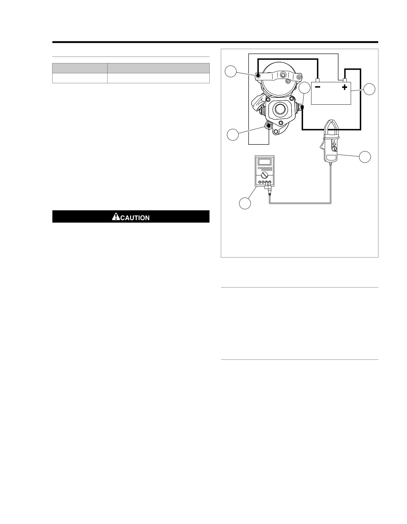
2. See Figure 3-6. Attach one heavy jumper cable (6 gauge
minimum).
a. Connect one end to the starter mounting flange.
5
b. Connect the other end to the battery (-) terminal of a
fully charged battery.
3. Connect a second heavy jumper cable (6 gauge minimum).
3
a. Connect one end to the battery (+) terminal of the
battery.
b. Connect the other end to the battery terminal on the
starter. Clamp the FLUKE AC/DC CURRENT PROBE
(Part No. HD-39617) around the cable.
4
1.
Mounting flange
2.
Battery
Keep fingers and clothing away from starter gear to pre-
3.
Current probe
vent personal injury. (00613b)
4.
Multimeter
4.
Connect a smaller jumper cable (14 gauge minimum).
5.
Relay terminal
6.
Batter terminal
a. Connect one end to the positive (+) terminal of the
battery.
Figure 3-6. Free Running Current Draw Test
b. Connect the other end to the solenoid relay terminal.
STARTER SOLENOID
5.
Check ammeter reading.
Do not disassemble solenoid. Before testing, disconnect field
a. Ammeter should show 90A maximum.
wire from solenoid motor terminal as shown in Figure 3-7.
b. If reading is higher, replace starter.
Perform each test for only 3-5 seconds to prevent damage to
c. If starter current draw on vehicle was over 120A and
solenoid.
this test was within specification, there may be a
Perform the solenoid Pull-in, Hold-in and Return tests together
problem with engine or primary drive.
in one continuous operation. Conduct all three tests one after
the other in the sequence given without interruption.
SOLENOID PULL-IN TEST
1. See Figure 3-7. Using a 12V battery, connect three sep-
arate test leads as follows:
a. Solenoid housing to negative battery post.
b. Solenoid motor terminal to negative battery post.
c. Solenoid relay terminal to positive battery post.
2. Observe starter shaft.
a. If starter shaft extends strongly, solenoid is working
properly.
b. If starter shaft does not extend strongly, replace
solenoid assembly.
2013 Softail Diagnostics: Starting and Charging 3-15