Harley Davidson Softail Delux FLSTN BIKE 2011-2015. Electrical Diagnostics - page 7
HOME
NO INSTRUMENT POWER
4. Ground Circuit Test
1. Using HARNESS CONNECTOR TEST KIT (Part No. HD-
PART NUMBER
TOOL NAME
41404), test continuity between BOB terminal 7 and
HD-41404
HARNESS CONNECTOR TEST KIT
ground.
HD-42682
BREAKOUT BOX
2. Is continuity present?
HD-46601
BREAKOUT BOX ADAPTERS
a. Yes. Replace speedometer. (6020)
b. No. Repair open in (BK/GN) wire. (5041)
Table 4-10. No Instrument Power Diagnostic Faults
DTC B1200
POSSIBLE CAUSES
Open battery circuit
PART NUMBER
TOOL NAME
Open ground circuit
HD-42682
BREAKOUT BOX
Open in CAN bus circuit to speedometer
HD-46601
BREAKOUT BOX ADAPTERS
1. Battery Circuit Test
Table 4-11. DTC B1200 Diagnostic Faults
1. Turn IGN ON.
POSSIBLE CAUSES
2. Does the headlamp or tail lamp illuminate?
Open in speedometer battery power circuit
a. Yes. Go to Test 2.
Open in speedometer ground circuit
b. No. See 2.4 NO VEHICLE POWER OR DTC U0100,
U0121, U0140, U0141, U0142, U0156, No Vehicle
1. Speedometer Voltage Test
Power: DTC U0140.
1. Turn IGN OFF.
2. Accessory Function Test
2. Connect BREAKOUT BOX (Part No. HD-42682) and
1. Attempt to start the vehicle.
BREAKOUT BOX ADAPTERS (Part No. HD-46601) to
the wiring harness [39B], leaving [39A] disconnected. See
2. Does the engine crank?
1.2 DIAGNOSTIC TOOLS.
a. Yes. Go to Test 3.
3. Test voltage between BOB terminal 5 and ground.
b. No. See
2.3 ODOMETER SELF-DIAGNOSTIC
4. Is battery voltage present?
INOPERATIVE, DTC U0001, U0011, B2274.
a. Yes. Go to Test 2.
3. Battery Circuit to Speedometer Test
b. No. Repair open in (R/O) wire.
1. Turn IGN OFF.
2. Speedometer Ground Test
2. Connect BREAKOUT BOX ADAPTERS (Part No. HD-
1. Test voltage between BOB terminals 5 and 7.
46601) to [39]. Attach connectors from BREAKOUT BOX
(Part No. HD-42682) to harness adapters leaving [39A]
2. Is battery voltage present?
disconnected. See 1.2 DIAGNOSTIC TOOLS.
a. Yes. Replace speedometer.
3. Test voltage between BOB terminal 5 and ground.
b. No. Repair open in ground circuit.
4. Is battery voltage present?
a. Yes. Go to Test 4.
b. No. Repair open between [39B] terminal 5 and [64B]
socket terminal 2 (R/O) wire. (5041)
4-16 2013 Softail Diagnostics: Instruments
HOME
INDICATOR LAMPS
4.5
which is illuminated when no DTCs are set, before attempting
DESCRIPTION AND OPERATION
to diagnose other possible causes.
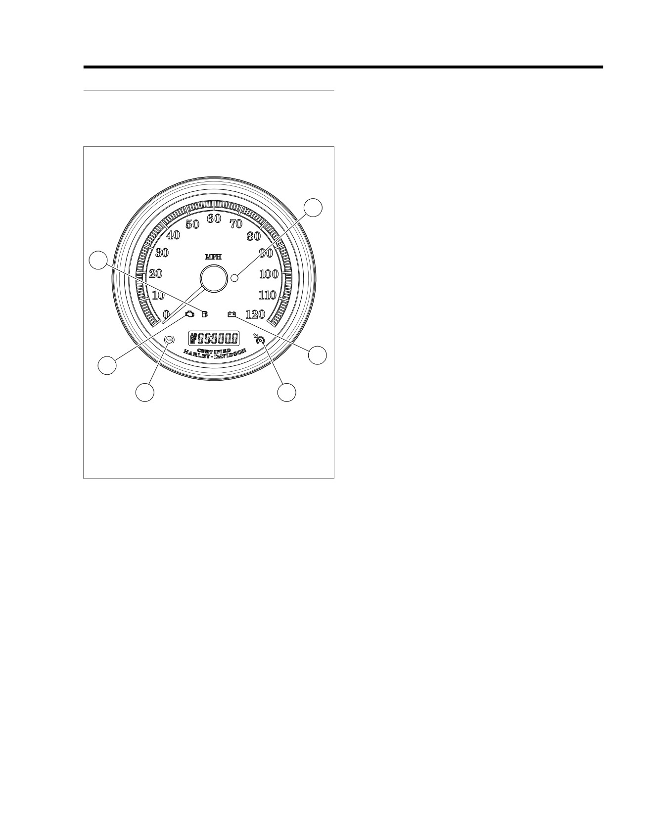
See Figure 4-10. The battery, check engine, security, sixth
gear, cruise control, ABS and low fuel indicators are located
Security Lamp
in the speedometer. The other indicators are located in the
When the IGN is turned ON, the security lamp will illuminate
indicator bar separate from the speedometer.
for approximately four seconds and then turn off. The BCM
controls the security lamp by sending a CAN message to the
ed03268
speedometer. After the security lamp turns off following the
first four second illumination period, one of two events may
occur.
•
The lamp remains off. This indicates there are no current
4
fault conditions or stored DTCs currently detected by the
BCM.
•
If the lamp remains on beyond the four-second period, a
current DTC exists.
3
Check Engine Lamp
When the IGN is ON, the check engine lamp will illuminate for
approximately four seconds and then turn off. The ECM controls
the check engine lamp by sending a CAN message to the
speedometer. After the check engine lamp turns off following
the first four second illumination period, one of two events may
occur.
5
•
The lamp remains off. This indicates there are no current
2
fault conditions or stored DTCs currently detected by the
ECM.
1
6
•
If the lamp remains on beyond the four-second period, a
current DTC exists.
1.
ABS lamp (if equipped)
2.
Check engine lamp
The check engine lamp may not illuminate for less than 4
3.
Low fuel lamp
seconds under the following conditions:
4.
Security lamp
•
IGN OFF/ON within 5 seconds.
5.
Battery
6.
Cruise enabled lamp (not used)
•
Trip switch activated, then IGN ON within 5 seconds.
Figure 4-10. Indicator Lamps
•
Run/stop switch cycled, then IGN ON within 5 seconds.
•
Security armed vehicles that are moved, then IGN ON, or
ABS Indicator
IGN ON and FOB response is not immediately received
(interference).
The speedometer illuminates the ABS indicator when the fol-
lowing occurs:
Current DTC notification is not affected by above conditions.
•
The ECU detects an ABS disabling malfunction. The ECU
Low Battery Lamp
sends a serial data message to the instrument requesting
The BCM sends a message to the speedometer to control the
illumination.
low battery lamp. The speedometer will turn the lamp on if the
•
The speedometer performs a bulb check.
BCM identifies a low voltage condition on [259] terminal 1.
•
The speedometer detects a loss of communication with
Low Fuel Indicator
the ECU.
See Figure 4-11. The low fuel indicator is controlled at terminal
•
The ABS light may flash when the IGN is turned on. This
9 (W/Y) of the speedometer. The fuel gauge or resistor
will continue until the vehicle is driven to verify WSS
assembly sends voltage on the (W/Y) wire to the low fuel lamp
operation.
and fuel level sender. When the fuel drops below 1.0 gal (3.8
The ECU sends a message to the instrument when a malfunc-
L), it signals the speedometer to activate the low fuel lamp.
tion that disables ABS operation is detected. Depending on
The low fuel lamp will also flash on and off at a steady rate if
the fault, the ABS indicator may stay on even after the malfunc-
there is a problem with the circuit.
tion is corrected. The indicator will not go off until the vehicle
The low fuel lamp will not turn off until there is sufficient fuel in
is operated at speeds greater than 10 mph (16 km/h). It is
the tank, the ignition switch has been turned off and back on,
important to verify that this is not the cause of an ABS indicator,
and the vehicle has begun forward speed.
2013 Softail Diagnostics: Instruments 4-17
HOME
Neutral Indicator
ed03297
1
See Figure 4-14. The neutral indicator is controlled through
the (W) wire connected to the speedometer. When the trans-
mission is in neutral, the neutral switch closes and supplies a
2
ground to the BCM on terminal D3. The BCM then sends a
message to the speedometer over the CAN bus indicating the
3
transmission is in neutral. The speedometer supplies ground
to the neutral indicator causing it to illuminate.
ed03335
4
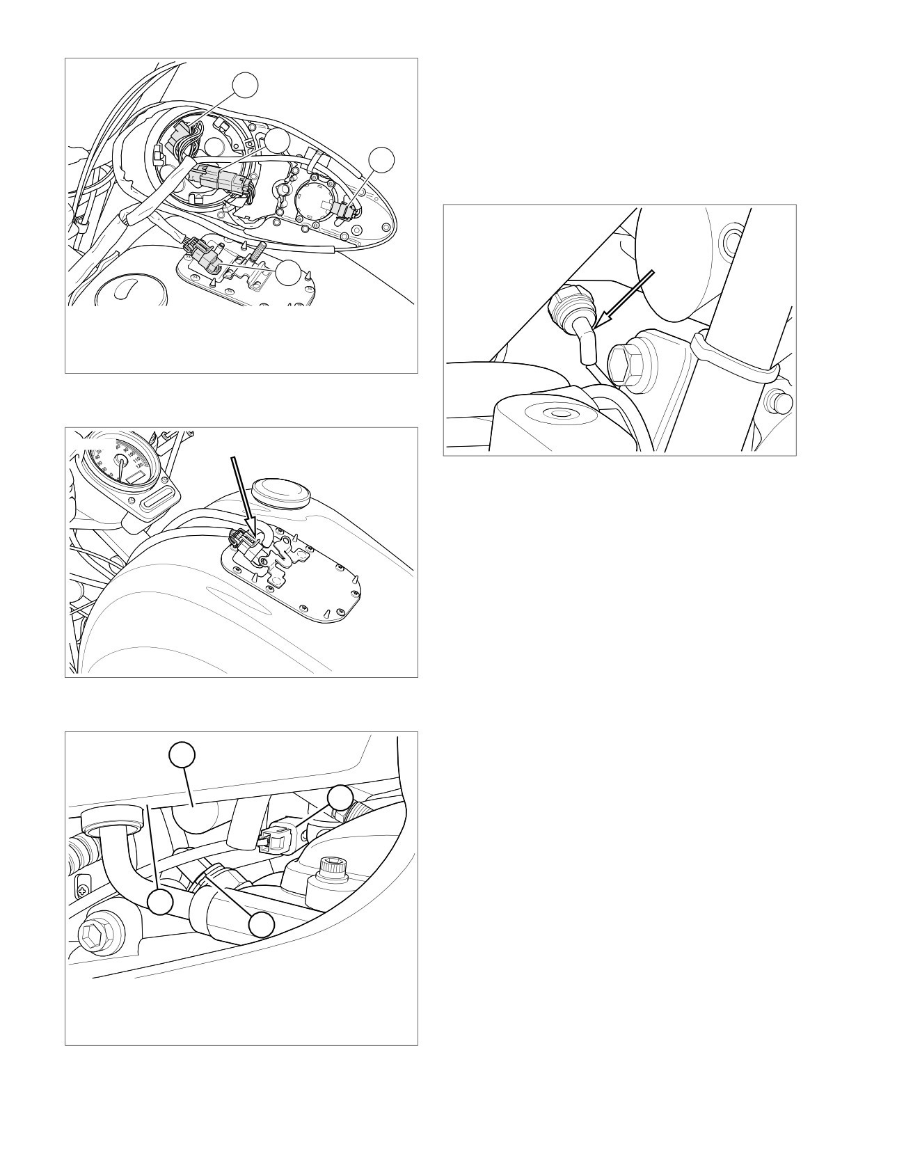
1. Speedometer [39]
2. Indicator lamps [21]
3. Ignition switch [33]
4. Fuel pump and sender [141]
Figure 4-11. Under Console: Except FXS/B
ed03298
Figure 4-14. Oil Pressure Switch [120]
Oil Pressure Indicator
See Figure 4-14. The oil pressure indicator is connected to the
speedometer. The switch closes when oil pressure is low and
supplies ground to the BCM at terminal E3. The BCM then
sends a message to the speedometer over the CAN bus
indicating the oil pressure is low. The speedometer supplies
ground to the oil pressure indicator causing it to illuminate. This
is why the oil pressure indicator is illuminated with the IGN ON
and the engine OFF.
Turn Signal Indicators
Figure 4-12. Under Console [141]: FXS/B Typical
The turn signal indicators are controlled by the speedometer.
When the BCM receives a CAN bus message from the left or
right turn signal switch it flashes the correct turn signals. At the
ed03319
same time the BCM sends a message to the speedometer
1
over the CAN bus indicating which turn signal to operate. The
speedometer supplies ground to the corresponding turn signal
indicator causing it to illuminate.
2
High Beam Indicator
This circuit is grounded by the speedometer when the head-
lamp switch is placed in the high beam position. In the high
position, a message is sent over the CAN bus to the speedo-
meter and the BCM. The speedometer controls the indicator
4
and the BCM controls the headlamp.
3
Diagnostic Tips
After replacing a component in the fuel circuit, verify the tank
is full of fuel and that the main fuse is removed for 2 minutes
1. Starter
and reinstalled to turn low fuel lamp off.
2. Starter solenoid [128]
Some unauthorized P&A fuel gauges may cause the fuel circuit
3. Neutral switch [131]
to report inaccurate readings.
4. Oil tank
Figure 4-13. Under Oil Tank Right Side
4-18 2013 Softail Diagnostics: Instruments
HOME
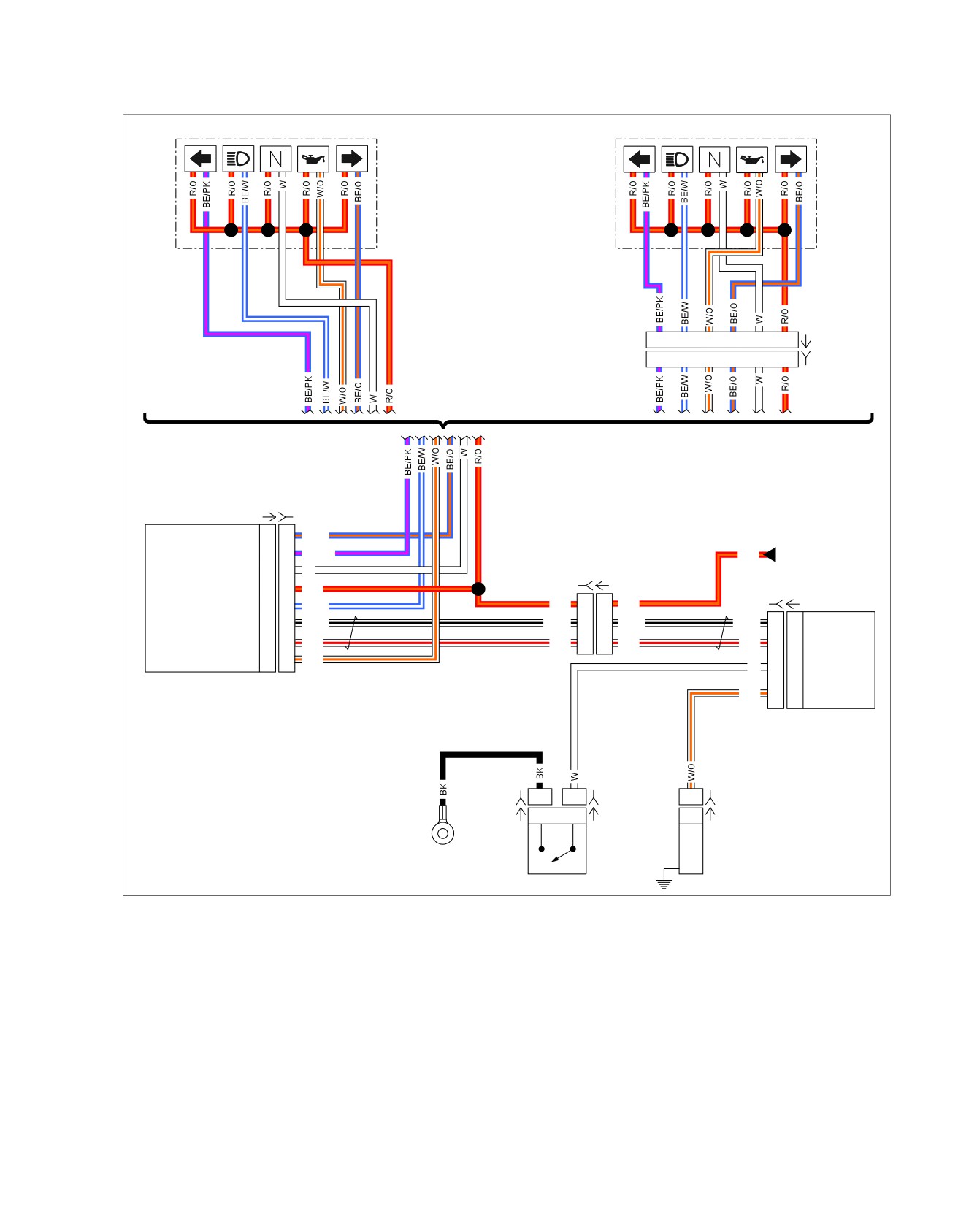
diagram(s) and diagnostic procedure(s), including the color of
Connector Information
the harness test kit terminal probes, see B.1 CONNECTORS.
For additional information about the connectors in the following
em01521
Indicators
Indicators
1
2
3
4
5
6
[21A]
1
2
3
4
5
6
[21B]
(FXS/B)
(Except FXS/B)
[39A] [39B]
Speedometer
Right Turn Indicator
12
12
BE/O
Battery
Left T
urn Indicator
10
10
BE/PK
R/O
Fuse
Neutral Indicator
6
6
W
[20A] [20B]
Battery Fuse
5
5
R/O
[242B] [242A]
High Beam Indicator
4
4
BE/W
R/O
6
6
R/O
BCM
CAN Low
8
8
W/BK
W/BK
3
3
W/BK
W/BK
E2
E2
CAN Low
CAN High
2
2
W/R
W/R
1
1
W/R
W/R
D2
D2
CAN High
Oil Pressure Indicator
1
1
W/O
Neutral Switch
W
D3
D3
Input
Oil Pressure
W/O
E3
E3
Switch Input
[131B-2]
1
1
[131B-1]
1
[120B]
[131A-2]
1
1
[131A-1]
1
[120A]
Oil Pressure
GND 2
Switch
Neutral Switch
Figure 4-15. Indicator Lamps
2013 Softail Diagnostics: Instruments 4-19
HOME
3. Verify fuel tank is at least half full.
LOW FUEL LAMP ALWAYS ON
4. Is fuel tank at least half full?
PART NUMBER
TOOL NAME
a. Yes. Go to Test 6.
HD-42682
BREAKOUT BOX
b. No. Go to Test 5.
HD-46601
BREAKOUT BOX ADAPTERS
5. Fuel Sender High Test
1. Turn IGN ON.
Table 4-12. Low Fuel Lamp Always On Diagnostic Faults
2. Record voltage between BOB terminal 9 and ground.
POSSIBLE CAUSES
Fuel pump and sender assembly malfunction
3. Turn IGN OFF.
Fuel system reset
4. Fill tank with fuel.
Excessive resistance in fuel sender circuit
5. Turn IGN ON.
6. Record voltage between BOB terminal 9 and ground.
1. Fuel Sender Circuit Resistance Test
1. Turn IGN OFF.
7. Did voltage decrease?
a. Yes. Go to Test 7.
2. Disconnect fuel pump [141].
b. No. Replace fuel sender.
3. Connect BREAKOUT BOX ADAPTERS (Part No. HD-
46601) to [39]. Attach connectors from BREAKOUT BOX
6. Fuel Sender Low Test
(Part No. HD-42682) between harness adapters [39A] and
[39B].
1. Turn IGN ON.
4. Test resistance between BOB terminal 9 and [141B] ter-
2. Record voltage between BOB terminal 9 and ground.
minal B (W/Y).
3. Turn IGN OFF.
5. Is resistance greater than 0.5 Ohms?
4. Drain fuel tank.
a. Yes. Repair excessive resistance between [39B] ter-
minal 9 and [141B] terminal B (W/Y).
5. Turn IGN ON.
b. No. With fuel gauge. Go to Test 2.
6. Record voltage between BOB terminal 9 and ground.
c. No. Without fuel gauge. Go to Test 3.
7. Did voltage increase?
a. Yes. Go to Test 7.
2. Fuel Gauge Circuit Resistance Test
b. No. Replace fuel sender.
1. Disconnect fuel gauge [117].
7. Speedometer Test
2. Test resistance between BOB terminal 9 and [117B] ter-
minal 2 (W/Y).
1. Turn IGN OFF.
3. Is resistance greater than 0.5 Ohms?
2. Fill tank with fuel if needed.
a. Yes. Repair excessive resistance between [39B] ter-
3. Remove main fuse for 2 minutes and install.
minal 9 and [117B] terminal 2 (W/Y).
4. Turn IGN ON.
b. No. Go to Test 4.
5. Is indicator still illuminated?
3. Resistance Assembly Circuit Resistance
a. Yes. Replace speedometer.
Test
b. No. System working correctly.
1. Disconnect resistance assembly [200].
2. Test resistance between BOB terminal 9 and [200B] ter-
minal 2 (W/Y).
3. Is resistance greater than 0.5 Ohms?
a. Yes. Repair excessive resistance between [39B] ter-
minal 9 and [200B] terminal 2 (W/Y).
b. No. Go to Test 4.
4. Fuel Level Test
1. Connect [141].
2. Connect [117] or [200].
4-20 2013 Softail Diagnostics: Instruments

HOME
6. Is battery voltage present?
OIL PRESSURE LAMP ALWAYS ON
a. Yes. Go to Test 6.
PART NUMBER
TOOL NAME
b. No. Replace BCM. (5863)
HD-42682
BREAKOUT BOX
5. Mechanical Test
HD-46601
BREAKOUT BOX ADAPTERS
1. Inspect engine for any issues that impact oil pressure.
HD-50390-1
BREAKOUT BOX
HD-50390-2
BCM CABLE
2. Using OIL PRESSURE GAUGE SET (Part No. HD-96921-
52D), verify engine oil pressure.
HD-50390-2-P
BCM OVERLAY
3. Is oil pressure within specification?
HD-96921-52D
OIL PRESSURE GAUGE SET
a. Yes. Replace oil pressure switch. (5161)
b. No. Repair as needed.
Table 4-13. Oil Pressure Lamp Always On Diagnostic
Faults
6. Oil Pressure Switch Circuit Test
POSSIBLE CAUSES
1. Disconnect [242A].
Short to ground in oil pressure circuit
2. Test continuity between BOB terminal E3 and ground.
Indicator malfunction
3. Is continuity present?
Mechanical issue
a. Yes. Repair short to ground. (5041)
Oil pressure switch malfunction
b. No. Go to Test 7.
1. Oil Pressure Lamp Function Test
7. Speedometer Test
1. Turn IGN ON.
1. Turn IGN OFF.
2. Does oil pressure lamp illuminate?
2. Remove BCM BOB.
a. Yes. Go to Test 2.
3. Connect [242].
b. No. See 4.5 INDICATOR LAMPS, Oil Pressure Lamp
Inoperative.
4. Connect BREAKOUT BOX ADAPTERS (Part No. HD-
46601) to [39]. Attach connectors from BREAKOUT BOX
2. Engine Running Test
(Part No. HD-42682) to harness adapters, leaving [39A]
disconnected. See 1.2 DIAGNOSTIC TOOLS.
1. Start engine.
5. Test continuity between BOB terminal 1 and ground.
2. Does oil pressure lamp turn OFF and stay off?
a. Yes. Oil pressure lamp is operating properly. Test for
6. Is continuity present?
intermittent. See
1.3
DIAGNOSTICS AND
a. Yes. Repair short to ground in (W/O) wire. (5041)
TROUBLESHOOTING, Wiggle Test.
b. No. Replace speedometer. (6020)
b. No. Go to Test 3.
OIL PRESSURE LAMP INOPERATIVE
3. Oil Pressure Sensor Test
1. Disconnect oil pressure switch [120].
PART NUMBER
TOOL NAME
2. Does oil pressure lamp turn OFF when the engine is run-
HD-41404
HARNESS CONNECTOR TEST KIT
ning?
HD-42682
BREAKOUT BOX
a. Yes. Go to Test 5.
HD-46601
BREAKOUT BOX ADAPTERS
b. No. Go to Test 4.
Table 4-14. Oil Pressure Lamp Inoperative Diagnostic
4. Oil Pressure Circuit Test
Faults
1. Turn IGN OFF.
POSSIBLE CAUSES
2. Connect the BREAKOUT BOX (Part No. HD-50390-1) and
Open oil pressure circuit
BCM CABLE (Part No. HD-50390-2) between wire harness
[242B] and [242A]. See 1.2 DIAGNOSTIC TOOLS.
Indicator malfunction
3. Verify BCM OVERLAY (Part No. HD-50390-2-P) is in
1. Oil Pressure Lamp Function Test
position on BOB.
1. Turn IGN ON.
4. Turn IGN ON.
5. Test voltage between BOB terminal E3 and ground.
2013 Softail Diagnostics: Instruments 4-21
HOME
2. Does oil pressure lamp illuminate?
2. Did neutral lamp turn OFF?
a. Yes. Test for intermittent. See 1.3 DIAGNOSTICS
a. Yes. Replace speedometer. (6020)
AND TROUBLESHOOTING, Wiggle Test.
b. No. Repair short to ground in (W) wire between
b. No. Go to Test 2.
neutral indicator and speedometer. (5041)
2. Speedometer Test
NEUTRAL LAMP INOPERATIVE
1. Turn IGN OFF.
PART NUMBER
TOOL NAME
2. Disconnect speedometer [39].
HD-41404
HARNESS CONNECTOR TEST KIT
3. Connect BREAKOUT BOX ADAPTERS (Part No. HD-
HD-42682
BREAKOUT BOX
46601) to [39]. Attach connectors from BREAKOUT BOX
(Part No. HD-42682) to harness adapters, leaving [39A]
HD-46601
BREAKOUT BOX ADAPTERS
disconnected.
HD-50390-1
BREAKOUT BOX
4. Turn IGN ON.
HD-50390-2
BCM CABLE
5. Using HARNESS CONNECTOR TEST KIT (Part No. HD-
HD-50390-2-P
BCM OVERLAY
41404), jumper BOB terminal 1 to ground.
6. Does oil pressure lamp turn ON?
Table 4-16. Neutral Lamp Inoperative Diagnostic Faults
a. Yes. Replace speedometer. (6020)
POSSIBLE CAUSES
b. No. FXS/B. Repair or replace the indicator harness.
Neutral switch malfunction
(5191)
Open ground circuit
c. No. Except FXS/B. Go to Test 3.
Open neutral switch circuit
3. Oil Pressure Circuit Test
Indicator malfunction
1. Turn IGN OFF.
1. Neutral Lamp Function Test
2. Disconnect indicator [21]
1. With the vehicle in neutral, turn IGN ON.
3. Test continuity between [21B] terminal 3 (W) wire and
2. Does neutral lamp illuminate?
BOB terminal 1.
a. Yes. Test for intermittent. See 1.3 DIAGNOSTICS
4. Is continuity present?
AND TROUBLESHOOTING, Wiggle Test.
a. Yes. Repair or replace the indicator harness. (5191)
b. No. Go to Test 2.
b. No. Repair open between [21] and [39] (W/O) wire.
(5041)
2. BCM Message Test
1. Verify transmission is in neutral.
NEUTRAL LAMP ALWAYS ON
2. With clutch lever released, start engine.
Table 4-15. Neutral Lamp Always On Diagnostic Faults
3. Does engine start?
a. Yes. Go to Test 6.
POSSIBLE CAUSES
Short to ground in neutral switch circuit
b. No. Go to Test 3.
Short to ground in neutral indicator circuit
3. Neutral Switch Test
1. Neutral Lamp Function Test
1. Turn IGN OFF.
1. With the vehicle in neutral, turn IGN ON.
2. Disconnect the neutral switch [131].
2. Does neutral lamp illuminate?
3. Using HARNESS CONNECTOR TEST KIT (Part No. HD-
a. Yes. Go to Test 2.
41404), jump the (W) wire to the (BK) ground wire.
b. No. See 4.5 INDICATOR LAMPS, Neutral Lamp
4. Does neutral lamp turn ON?
Inoperative.
a. Yes. Replace neutral switch. (5157)
b. No. Go to Test 4.
2. Indicator Harness Test
1. Disconnect speedometer [39].
4. Ground Wire Test
1. Jump the (W) wire of the neutral switch to ground.
4-22 2013 Softail Diagnostics: Instruments
HOME
2. Does neutral lamp turn on?
HIGH BEAM INDICATOR LAMP ALWAYS
a. Yes. Repair open in (BK) ground wire. (5041)
ON
b. No. Go to Test 5.
Table 4-17. High Beam Indicator Lamp Always On
5. Neutral Switch Power Circuit Open Test
Diagnostic Faults
1. Turn IGN OFF.
POSSIBLE CAUSES
2. Disconnect BCM [242].
Indicator malfunction
3. Connect the BREAKOUT BOX (Part No. HD-50390-1) and
Short to ground in high beam indicator circuit
BCM CABLE (Part No. HD-50390-2) between wire harness
[242B] and [242A]. See 1.2 DIAGNOSTIC TOOLS.
1. High Beam Indicator Function Test
1. With IGN ON, operate the headlamp switch.
4. Verify BCM OVERLAY (Part No. HD-50390-2-P) is in
position on BOB.
2. Do high and low beam headlamps function correctly?
5. Test continuity between terminal D3 and [131B-1] (W)
a. Yes. Go to Test 2.
wire.
b. No. See 5.7 HEADLAMPS: DTC B2131, B2132,
6. Is continuity present?
B2133, B2134, B2136, B2137, B2138, B2139.
a. Yes. Replace BCM. (5863)
2. High Beam Indicator Circuit Test
b. No. Repair open in (W) wire between indicators and
1. With IGN OFF, disconnect speedometer [39].
neutral switch. (5041)
2. Turn IGN ON.
6. Speedometer Test
3. Does high beam indicator illuminate?
1. Turn IGN OFF.
a. Yes. FXS/B. Replace indicator harness. (5191)
2. Disconnect speedometer [39].
b. Yes. Except FXS/B. Go to Test 3.
3. Connect BREAKOUT BOX ADAPTERS (Part No. HD-
c. No. Replace speedometer. (6020)
46601) to [39]. Attach connectors from BREAKOUT BOX
(Part No. HD-42682) to harness adapters, leaving [39A]
3. High Beam Indicator Circuit Short to
disconnected.
Ground Test
4. Turn IGN ON.
1. Turn IGN OFF.
5. Jump BOB terminal 6 to ground.
2. Disconnect indicators [21].
6. Does neutral lamp illuminate?
3. Test continuity between [21B] terminal 2 and ground.
a. Yes. Replace speedometer. (6020)
4. Is continuity present?
b. No. FXS/B. Replace indicator harness. (5191)
a. Yes. Repair short to ground in (BE/W) wire between
c. No. Except FXS/B. Go to Test 7.
[21B] and [39B]. (5041)
b. No. Replace indicator harness. (5191)
7. Neutral Indicator Circuit Test
1. Turn IGN OFF.
HIGH BEAM INDICATOR LAMP
2. Disconnect indicator [21].
INOPERATIVE
3. Test continuity between [21B] terminal 5 and BOB terminal
6.
PART NUMBER
TOOL NAME
HD-42682
BREAKOUT BOX
4. Is continuity present?
a. Yes. Replace indicator harness. (5191)
HD-46601
BREAKOUT BOX ADAPTERS
b. No. Repair open in (W) wire between [21B] and [39B].
(5041)
Table 4-18. High Beam Indicator Lamp Inoperative
Diagnostic Faults
POSSIBLE CAUSES
Indicator malfunction
Open high beam indicator circuit
1. High Beam Indicator Function Test
1. With IGN ON, operate the headlamp switch.
2013 Softail Diagnostics: Instruments 4-23

HOME
2. Do high and low beam headlamps function correctly?
3. Does turn signal indicator illuminate?
a. Yes. Go to Test 2.
a. Yes. FXS/B. Replace indicator harness. (5191)
b. No. See 5.7 HEADLAMPS: DTC B2131, B2132,
b. Yes. Except FXS/B. Go to Test 3.
B2133, B2134, B2136, B2137, B2138, B2139.
c. No. Replace speedometer. (6020)
2. High Beam Indicator Circuit Test
3. Turn Signal Indicator Circuit Short to
1. Turn IGN OFF.
Ground Test
2. Disconnect speedometer [39].
1. Turn IGN OFF.
3. Turn IGN ON.
2. Disconnect indicators [21].
4. Connect BREAKOUT BOX ADAPTERS (Part No. HD-
3. Test continuity between [21B] terminal 1 and ground (left)
46601) to [39]. Attach connectors from BREAKOUT BOX
or [21B] terminal 4 and ground (right).
(Part No. HD-42682) to harness adapters, leaving [39A]
disconnected.
4. Is continuity present?
a. Yes. Repair short to ground in (BE/PK) (left) or (BE/O)
5. Jump BOB terminal 4 to ground.
(right) between [21B] and [39B]. (5041)
6. Does high beam indicator illuminate?
b. No. Replace indicator harness. (5191)
a. Yes. Replace speedometer. (6020)
b. No. FXS/B. Replace indicator harness. (5191)
TURN SIGNAL INDICATOR INOPERATIVE
c. No. Except FXS/B. Go to Test 3.
PART NUMBER
TOOL NAME
3. High Beam Indicator Circuit Open Test
HD-42682
BREAKOUT BOX
HD-46601
BREAKOUT BOX ADAPTERS
1. Turn IGN OFF.
2. Disconnect indicator [21].
Table 4-20. Turn Signal Indicator Inoperative Diagnostic
3. Test continuity between [21B] terminal 2 and BOB terminal
Faults
4.
POSSIBLE CAUSES
4. Is continuity present?
a. Yes. Replace indicator harness. (5191)
Indicator malfunction
Open turn signal circuit
b. No. Repair open in (BE/W) wire between [21B] and
[39B]. (5041)
1. Turn Signal Function Test
TURN SIGNAL INDICATOR LAMP ALWAYS
1. With IGN ON, operate turn signals.
ON
2. Do turn signals operate?
a. Yes. Go to Test 2.
Table 4-19. Turn Signal Indicator Lamp Always On
b. No. See 5.3 TURN SIGNALS.
Diagnostic Faults
POSSIBLE CAUSES
2. Turn Signal Indicator Circuit Test
Indicator malfunction
1. Turn IGN OFF.
Short to ground turn signal circuit
2. Disconnect speedometer [39].
1. Turn Signal Function Test
3. Connect BREAKOUT BOX ADAPTERS (Part No. HD-
46601) to [39]. Attach connectors from BREAKOUT BOX
1. With IGN ON, operate turn signals.
(Part No. HD-42682) to harness adapters, leaving [39A]
2. Do turn signals operate?
disconnected.
a. Yes. Go to Test 2.
4. Turn IGN ON.
b. No. See 5.3 TURN SIGNALS.
5. Jump BOB terminal 10 (left) or terminal 12 (right) to
ground.
2. Turn Signal Indicator Circuit Test
6. Does turn signal indicator illuminate?
1. With IGN OFF, disconnect speedometer [39].
a. Yes. Replace speedometer. (6020)
2. Turn IGN ON.
b. No. FXS/B. Replace indicator harness. (5191)
c. No. Except FXS/B. Go to Test 3.
4-24 2013 Softail Diagnostics: Instruments
HOME
4. Is continuity present?
3. Turn Signal Indicator Circuit Open Test
a. Yes. Replace indicator harness. (5191)
1. Turn IGN OFF.
b. No. Repair open in (BE/PK) (left) or (BE/O) (right)
2. Disconnect [21].
between [21B] and [39B]. (5041)
3. Test continuity between [21B] terminal 1 and BOB terminal
10 (left) or between [21B] terminal 4 and BOB terminal 12
(right).
2013 Softail Diagnostics: Instruments 4-25
HOME
GAUGES
4.6
Inoperative gauges occur if:
THEORY OF OPERATION
•
Sender or fuel gauge not grounded.
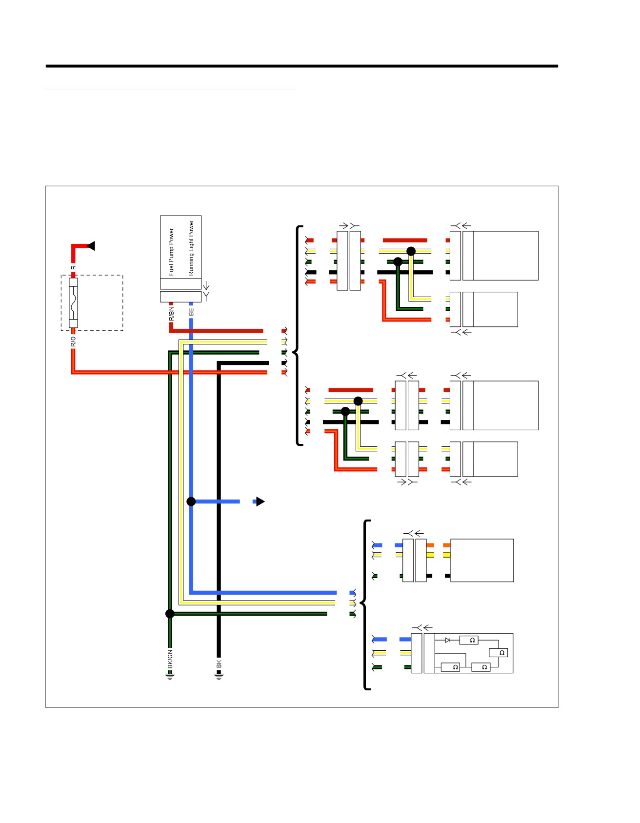
See Figure 4-16. With IGN ON, the fuel gauge receives 12V
through the running lamp circuit. Current flows through the
•
Malfunction in sender or fuel gauge.
gauge and variable resistor in the fuel gauge sending unit to
•
Inoperative or disconnected wire to fuel gauge.
ground. The sending unit float controls the amount of resistance
in the variable resistor.
•
Corroded connections at fuel gauge.
Use the 4.6 GAUGES, Fuel Gauge Inaccurate, No DTCs to
test suspected components.
em01520
BCM
Fuel Pump
[20A] [20B]
[141B] [141A]
And
Sender
Main
R/BN
7
7
R/BN
R/BN
A
A
Fuel Pump Power
Harness
W/Y
4
4
W/Y
W/Y
B
B
Fuel Level Sender
(Except FXS/B)
BK/GN
2
2
BK/GN
BK/GN
C
C
Sender Ground
BK
8
8
BK
BK
D
D
Pump Ground
1
R/O
6
6
R/O
F4
J3
[242A]
F4
J3
[242B]
Battery
W/Y
9
9
Fuel Level
15A
BK/GN
7
7
Ground
R/O
5
5
Battery Fuse
2
[64B]
R/BN
Speedometer
W/Y
[39B] [39A]
BK/GN
Fuel Pump
BK
[13B] [13A]
[141B] [141A]
And
R/O
Sender
R/BN
R/BN
1
1
R/BN
A
A
Fuel Pump Power
W/Y
W/Y
2
2
W/Y
B
B
Fuel Level Sender
(FXS/B)
BK/GN
BK/GN
3
3
BK/GN
C
C
Sender Ground
BK
BK
4
4
BK
D
D
Pump Ground
R/O
W/Y
4
4
W/Y
9
9
Fuel Level
BK/GN
2
2
BK/GN
7
7
Ground
R/O
6
6
R/O
5
5
Battery Fuse
Speedometer
[20A] [20B]
[39B] [39A]
Main
BE Harness
[117B] [117A]
Fuel
Gauge
BE
1
1
O
Running Light Power
(Except FXS/B)
W/Y
2
2
Y
Fuel Level Sender
BK/GN
4
4
BK
Ground
BE
W/Y
BK/GN
[200B] [200A]
Resistor
ASSY
BE
1
1
36
(FXS/B)
W/Y
2
2
36
BK/GN
3
3
200
36
GND 1
GND 2
Figure 4-16. Fuel Sensor Circuit
4-26 2013 Softail Diagnostics: Instruments
HOME
FUEL GAUGE INACCURATE, NO DTCS
ed03320
PART NUMBER
TOOL NAME
HD-41404
HARNESS CONNECTOR TEST KIT
Table 4-21. Fuel Gauge Inaccurate, No DTCs Diagnostic
Faults
POSSIBLE CAUSES
Open in fuel gauge power circuit
Open in fuel gauge ground circuit
Fuel sender malfunction
Fuel gauge malfunction
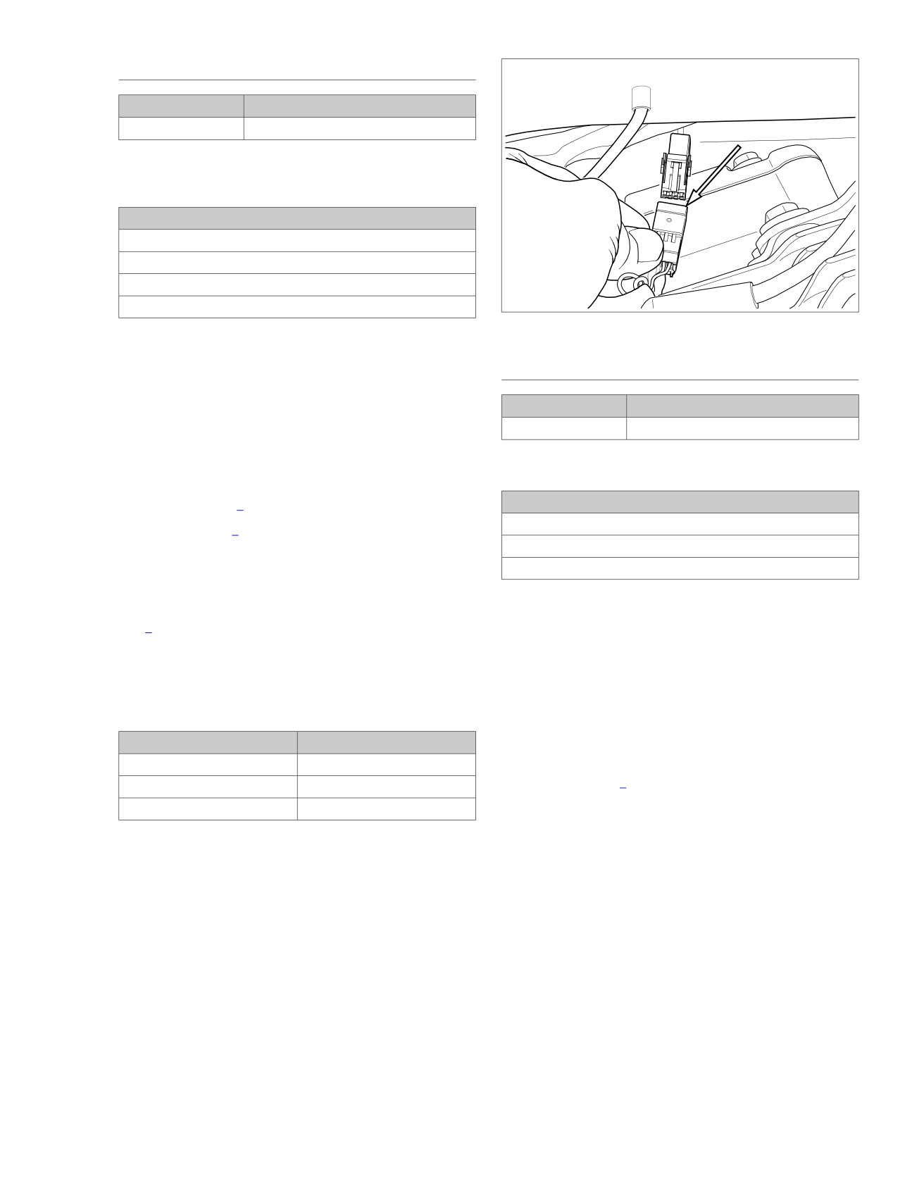
Figure 4-17. Fuel Gauge Connector
1. Fuel Gauge Test
1. Turn IGN OFF.
FUEL GAUGE INOPERATIVE
2. Disconnect fuel pump and sender [141].
PART NUMBER
TOOL NAME
3. Using HARNESS CONNECTOR TEST KIT (Part No. HD-
HD-41404
HARNESS CONNECTOR TEST KIT
41404), jumper [141B] terminal B to ground.
4. Turn IGN ON.
Table 4-23. Fuel Gauge Inoperative Diagnostic Faults
5. Does fuel gauge indicate full?
a. Yes. Go to Test 2.
POSSIBLE CAUSES
Open in power circuit
b. No. Go to Test 3.
Open in ground circuit
2. Sending Unit Test
Fuel gauge malfunction
1. Test resistance between [141A] terminals B and C.
1. Ignition Voltage Test
2. Is resistance within the specified range? Refer
to
Table 4-22.
1. Turn IGN OFF.
a. Yes. System operating properly.
2. Disconnect fuel gauge [117].
b. No. Replace fuel sender.
3. Turn IGN ON.
4. Using HARNESS CONNECTOR TEST KIT (Part No. HD-
Table 4-22. Fuel Sender Resistance Values
41404), test voltage between
[117B] terminal
1 and
ground.
FUEL LEVEL
RESISTANCE
Full
27-40 Ohms
5. Is battery voltage present?
Half-full
97-118 Ohms
a. Yes. Go to Test 2.
Empty
240-264 Ohms
b. No. Repair open in (BE) wire. (5041)
3. Fuel Gauge Circuit Test
2. Ground Circuit Test
1. Turn IGN OFF.
1. Test voltage between [117B] terminals 1 and 4.
2. Disconnect fuel gauge [117].
2. Is battery voltage present?
3. Turn IGN ON.
a. Yes. Replace fuel gauge. (6047)
4. Test voltage between [117B] terminals 1 and 4.
b. No. Repair open in the ground circuit. (5041)
5. Is battery voltage present?
a. Yes. Replace fuel gauge.
b. No. Repair open in (BE) or (BK/GN) wire.
2013 Softail Diagnostics: Instruments 4-27
NOTES
4-28 2013 Softail Diagnostics: Instruments
TABLE OF CONTENTS
SUBJECT
PAGE NO.
5.1 ACCESSORIES: DTC B2112, B2113, B2114
5-1
5.2 HORN: DTC B2126, B2127, B2128, B2129
5-8
5.3 TURN SIGNALS
5-11
5.4 DTC B1101, B1151
5-16
5.5 DTC B2141, B2143, B2144, B2146, B2148, B2149
5-18
5.6 DTC B2151, B2153, B2154, B2156, B2158, B2159
5-23
5.7 HEADLAMPS: DTC B2131, B2132, B2133, B2134, B2136, B2137, B2138, B2139
5-30
5.8 STOP LAMPS: DTC B2161, B2163, B2164, B2223
5-37
5.9 DTC B1103, B1153, B2210, B2212, B2250, B2251, B2252, B2253, B2254, B2260, B2261, B2262,
B2263, B2270
5-42
5.10 RUNNING LAMPS: DTC B2107, B2108, B2109, B2166, B2168, B2169
5-44
5.11 SECURITY SYSTEM
5-53
5.12 KEY FOB
5-56
5.13 SIREN
5-57
5.14 SERVICE AND EMERGENCY FUNCTIONS AND CONFIGURATIONS
5-59
5.15 DTC B2172, B2173
5-61
5.16 FAILS TO DISARM: DTC B2176, B2177, B2178
5-64
5.17 DTC B2183, B2188, B2193, B2198
5-71
5.18 DTC B2218
5-73
NOTES
HOME
ACCESSORIES:
DTC B2112, B2113, B2114
5.1
DESCRIPTION AND OPERATION
Conditions for Setting
The P&A battery circuit is connected to battery power through
The accessory circuit normally has power when the IGN is ON
the P&A fuse. This circuit supplies power to additional systems
or in the ACC positions. If the accessory circuit has power
on the vehicle. The P&A circuit runs from the fuse to the DLC
when the IGN is OFF, then DTC B2112 will set.
connector terminal 6.
DTC B2114 will set if the accessory circuit draws more than
There is also an accessory power circuit from the BCM terminal
15 Amps.
M2 that runs to the rear lighting and DLC connectors. This cir-
The other accessory circuit DTCs will set if the BCM identifies
cuit is energized by the BCM when the IGN is in the ACC or
them with the IGN ON or in the ACC position.
ON position.
Diagnostic Tips
Table 5-1. Code Description
This circuit may be used for aftermarket accessories or systems
for the vehicle. If a code is set and cannot be duplicated, verify
DTC
DESCRIPTION
that an aftermarket device did not cause the concern.
B2112
Accessory output shorted high
B2113
Accessory output shorted low
B2114
Accessory output overloaded
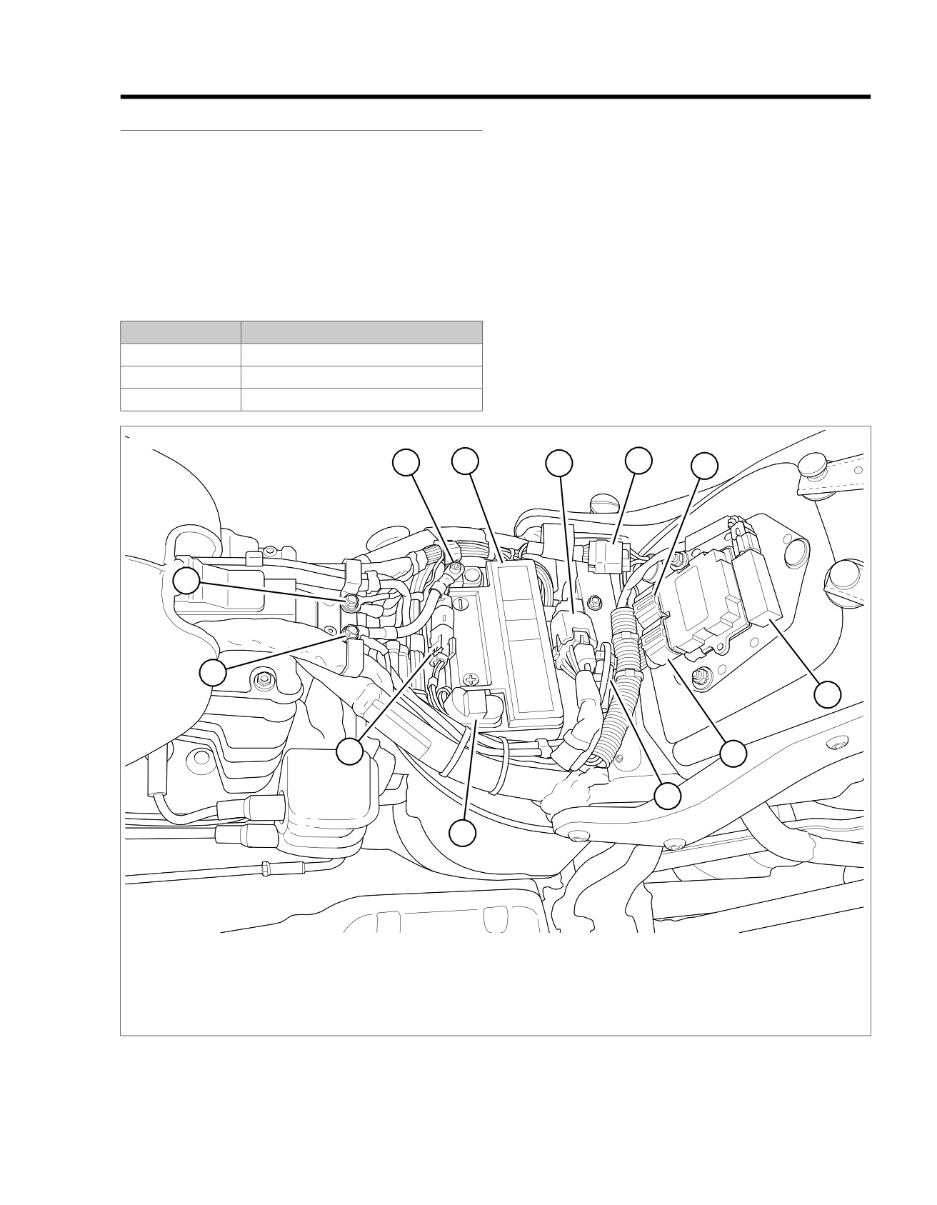
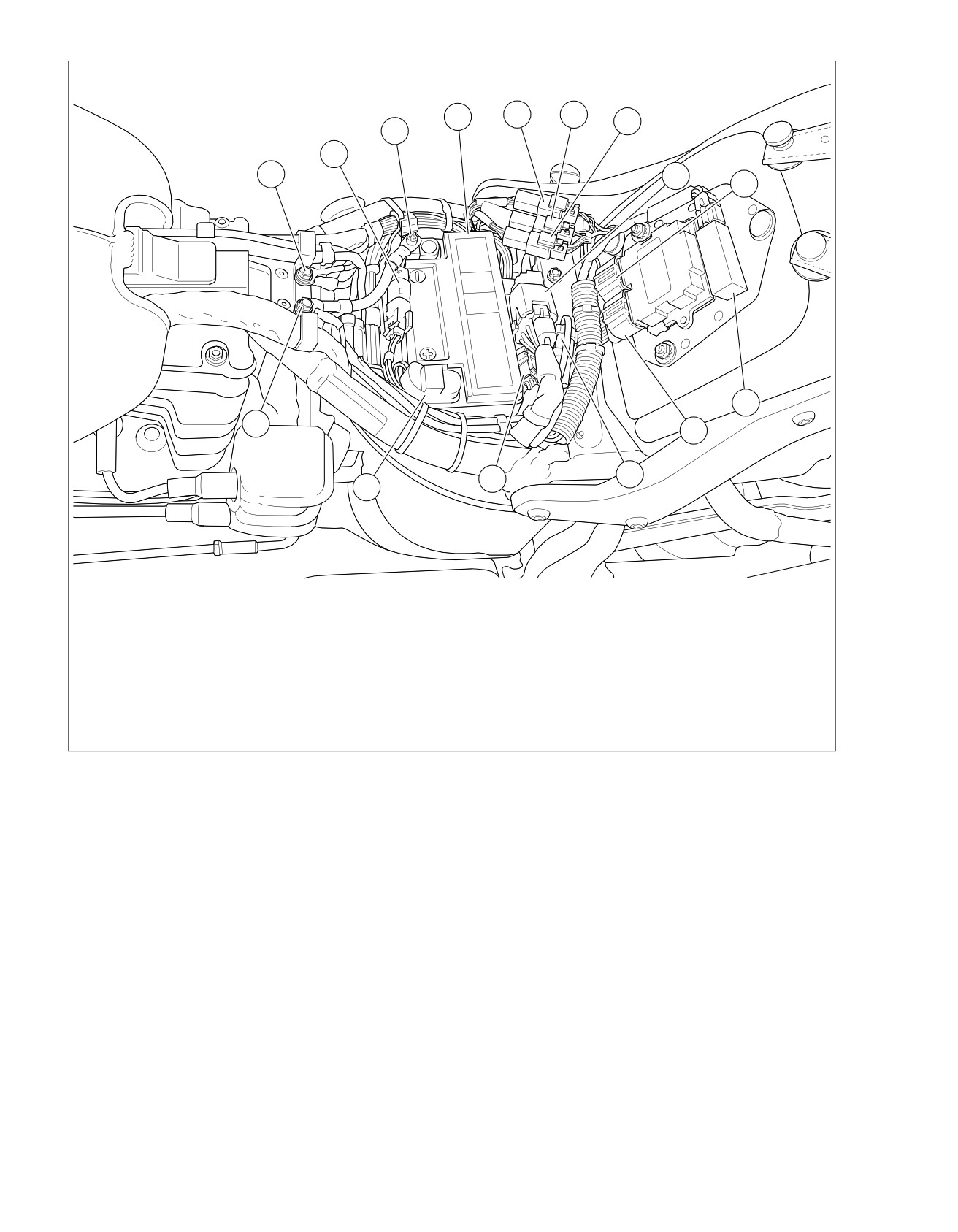
ed03300
1
2
3
4
5
12
11
6
10
7
8
9
1. Battery negative
7. ECM [78B-2]
2. Battery
8. DLC [91]
3. Fuse block [64]
9. Battery positive
4. Tail lamp harness to main harness [7]
10.
Rear HO2 sensor [137]
5. ECM [78B-1]
11. Ground [GND1]
6. Security antenna [209]
12. Ground [GND2]
Figure 5-1. Under Seat: Except FXS/B and FLS
2013 Softail Diagnostics: Accessories, Horn, Lighting and Security 5-1
HOME
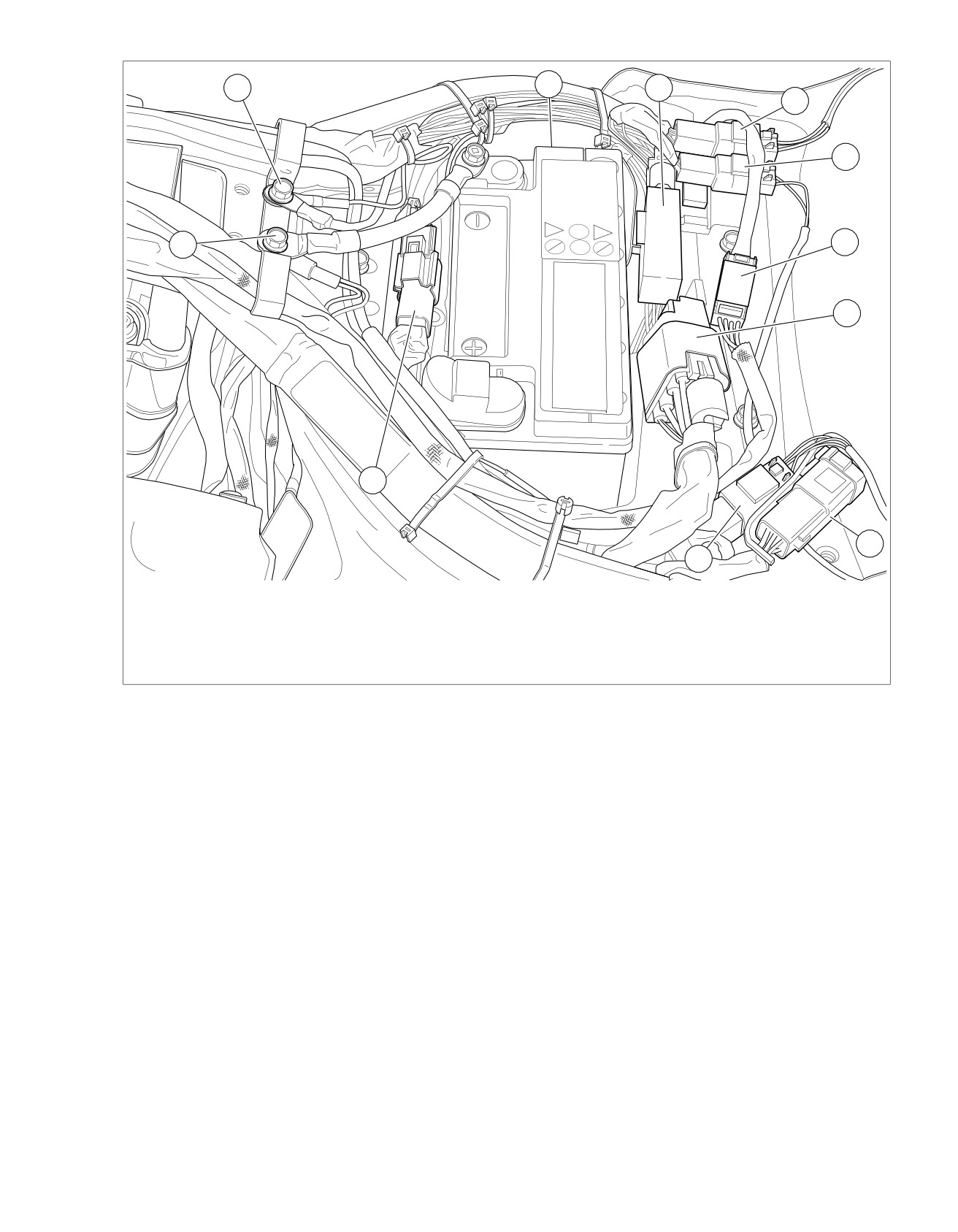
ed03468
2
3
4
5
1
15
14
6
7
8
13
9
10
11
12
1. Battery negative
9. ECM [78B-2]
2. Battery
10. DLC [91]
3. Tail lamp harness to main harness [40]
11. Fuel sender/pump jumper harness [13]
4. Left rear stop/tail/turn harness to main harness
12. Battery positive
[19]
13. Ground [GND1]
5. Right rear stop/tail/turn harness to main harness
14. Ground [GND2]
[18]
15. Rear HO2 sensor [137]
6. Fuse block [64]
7. ECM [78B-1]
8. Security antenna [209]
Figure 5-2. Under Seat: FXS and FLS
5-2 2013 Softail Diagnostics: Accessories, Horn, Lighting and Security
HOME
ed03415
2
3
4
5
6
1
7
8
11
9
10
1. GND 1
7. Fuel pump/sender [13]
2. GND 2
8. Fuse block connector [64]
3. Resistor pack [200] (behind battery)
9. DLC [91]
4. Security antenna connector [209]
10. Left rear lighting [19]
5. Right rear lighting [18]
11. Rear HO2S [137]
6. Tail/LP lamp [45]
Figure 5-3. Under Seat: FXSB
Connector Information
For additional information about the connectors in the following
diagram(s) and diagnostic procedure(s), including the color of
the harness test kit terminal probes, see B.1 CONNECTORS.
2013 Softail Diagnostics: Accessories, Horn, Lighting and Security 5-3
HOME
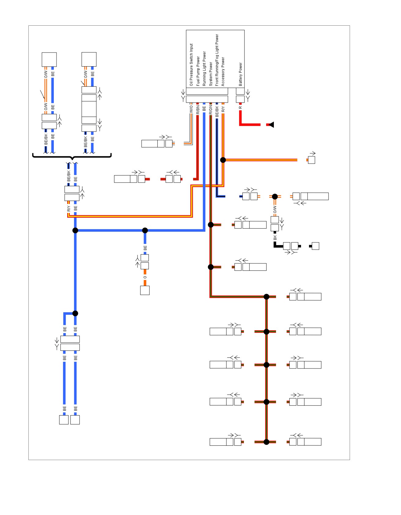
em00977
BCM
Stop/Tail
Tail
Lamp
Lamp
HDI
HDI
2
1
[93B]
[242A]
E3
F4
J3
L3
L4
M2
1
[259A]
2
1
[93A]
[242B]
E3
F4
J3
L3
L4
M2
1
[259B]
Circuit
Board
2
1
[40B]
1
3
[94A]
Battery
2
1
[40A]
R
Power
1
3
[94B]
[120A] [120B]
Distribution
Oil
Pressure
1
1
W/O
Switch
[91A]
R/Y
5
DLC
(FLSTN)
(Except
FLSTN)
[141A] [141B]
[20B] [20A]
A
A
R/BN
7
7
R/BN
Fuel
[38A] [38B]
2
7
[7B]
Pump
Position
2
7
[7A]
BE/BK
1
1
O/W
O/W
1
1
Lamp
[29B] [29A]
[179B] [179A]
1
[32A]
R/GN
1
1
1
[32B]
Active
Exhaust
Tip
1
1
BK
Lamp
[95B] [95A]
[117B]
1
[143A] [143B]
[117A]
1
R/GN
A
A
Purge
Solenoid
[178B] [178A]
Active
R/GN
1
1
Fuel
Intake
Gauge
[84A] [84B]
[85B] [85A]
Front Fuel
Rear Fuel
A
A
R/GN
R/GN
A
A
Injector
Injector
[31A]
3
4
[31B]
3
4
[138B] [138A]
[137A] [137B]
Front
Rear
1
1
R/GN
R/GN
1
1
HO2S
HO2S
[203FB] [203FA]
[203RA] [203RB]
Front ACR
1
1
R/GN
R/GN
1
1
Rear ACR
Right Front
Left Front
Turn Lamp
Turn Lamp
[83A] [83B]
[78B-2] [78A-2]
Ignition
A
A
R/GN
R/GN
16
16
ECM
Coil
Figure 5-4. Ignition and Accessory Power Distribution: Except FXS/B and FLS
5-4 2013 Softail Diagnostics: Accessories, Horn, Lighting and Security
HOME
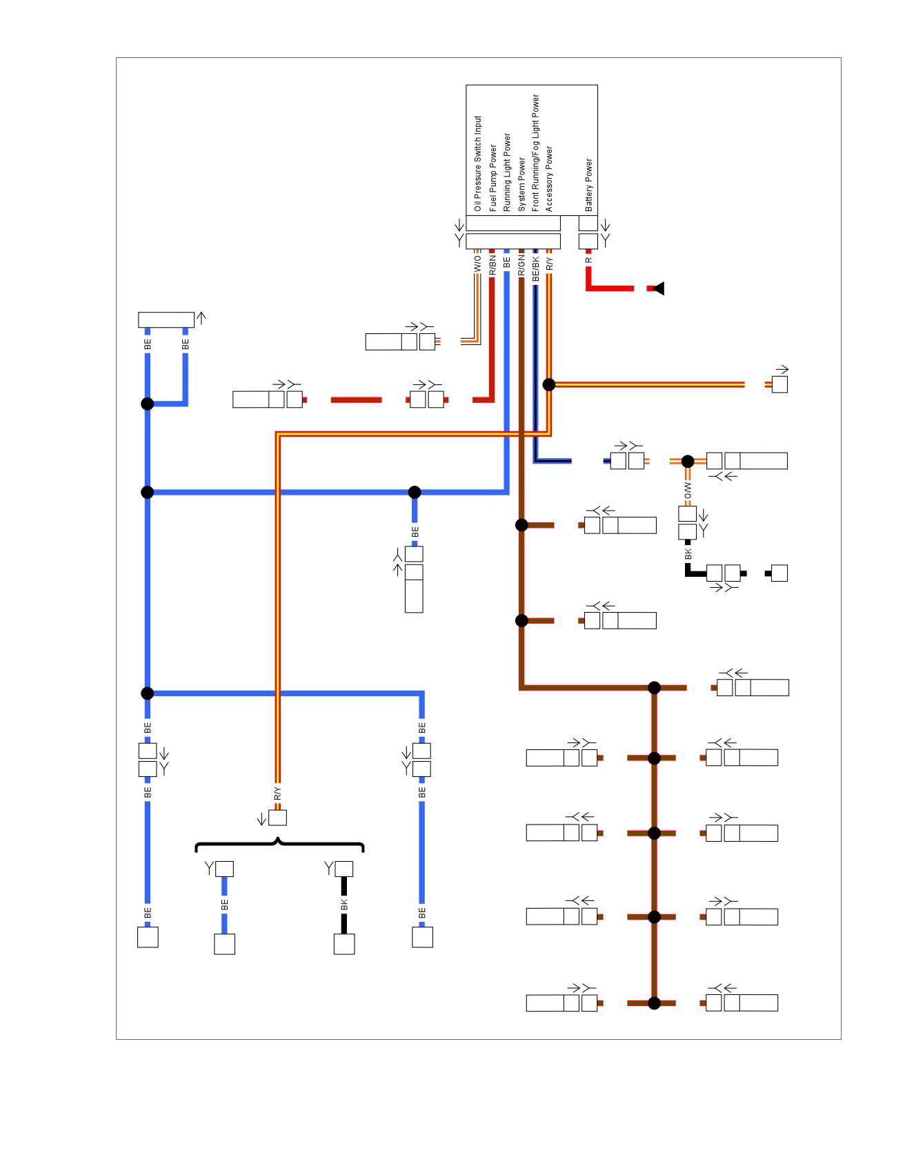
em01431
BCM
[242A]
E3
F4
J3
L3
L4
M2
1
[259A]
[242B]
E3
F4
J3
L3
L4 M2
1
[259B]
Battery
Not
R
Power
Used
Distribution
3
4
[31A]
[120A] [120B]
Oil
Pressure
1
1
W/O
Switch
[91A]
[141A] [141B]
[13A] [13B]
R/Y
5
DLC
Fuel
A
A
R/BN
R/BN
1
1
R/BN
Pump
[38A] [38B]
Position
BE/BK
1
1
O/W
1
1
Lamp
[29B] [29A]
[179B] [179A]
1
[32A]
R/GN
1
1
1
[32B]
Active
[200B]
1
Exhaust
[200A]
Tip
1
1
1
BK
Lamp
[95B] [95A]
[143A] [143B]
R/GN
A
A
Resistor
ASSY
Purge
Solenoid
[178B] [178A]
Active
R/GN
1
1
Intake
[84A] [84B]
[85B] [85A]
1
[19A]
[18A]
1
Front Fuel
Rear Fuel
A
A
R/GN
R/GN
A
A
Injector
Injector
1
[19B]
[18B]
1
[138B] [138A]
[137A] [137B]
[40A]
1
(Except
Front
Rear
(Canada)
Canada)
1
1
R/GN
R/GN
1
1
HO2S
HO2S
[40B]
1
[40B]
1
[203FB] [203FA]
[203RA] [203RB]
Front ACR
1
1
R/GN
R/GN
1
1
Rear ACR
Left
Right
LP/Stop/
LP
Stop/
Stop/
Tail
[83A] [83B]
[78B-2] [78A-2]
Tail/
Tail/
Turn
Turn
Ignition
A
A
R/GN
R/GN
16
16
ECM
Coil
Figure 5-5. Ignition and Accessory Power Distribution: FXS/B
2013 Softail Diagnostics: Accessories, Horn, Lighting and Security 5-5