Ford Mondeo (petrol engines). Manual - part 106
 

  Index      Ford     Ford Mondeo - service and repair manual (petrol engines)


Search            


Content   ..  104  105  106  107   ..


Ford Mondeo (petrol engines). Manual - part 106


10•4 Suspension and steering systems

pressed-steel lower side arms. A tie-bar on
each side supports the rear suspension
knuckles. The coil springs are separate from
the shock absorbers (see illustration).

A rear anti-roll bar is fitted to all models. On

SI models, the front and rear shock absorbers
are gas-filled; on other models, they are filled
with fluid. Self-levelling rear shock absorbers
are fitted as standard to Ghia Estate models.

A variable-ratio type rack-and-pinion

steering gear is fitted, together with a
conventional column and telescopic coupling,
incorporating two universal joints. Power-
assisted steering is fitted to all models. A
power steering system fluid cooler is fitted, in
front of the cooling system radiator on the
crossmember (see illustration). On models
with adaptive damping, a steering position
sensor with sensor disc is located above the
upper universal joint.

On models with adaptive damping, it is

possible to select a hard or soft setting for the
front and rear shock absorbers. The system is

computer-controlled; a switch is provided
near the handbrake lever for selection of
“Sport” or “Normal” mode. With this system, a
solenoid valve is fitted to each suspension
strut. When the valve is open, the hydraulic oil
inside the shock absorber is routed through a
bypass channel, making the action “softer”.
When the solenoid valve is closed, the shock
absorber action becomes “harder”. The
system takes into consideration the
roadspeed of the vehicle; at high speeds, the
shock absorbers are automatically set to
“hard”. The adaptive damping computer
module is located in the luggage
compartment, behind the rear seat, and
incorporates a self-test function. Adaptive
damping is not available on Estate models
(see illustrations).

When working on the suspension or

steering, you may come across nuts or bolts
which seem impossible to loosen. These nuts
and bolts on the underside of the vehicle are
continually subjected to water, road grime,

mud, etc, and can become rusted or seized,
making them extremely difficult to remove. In
order to unscrew these stubborn nuts and
bolts without damaging them (or other
components), use lots of penetrating oil, and
allow it to soak in for a while. Using a wire
brush to clean exposed threads will also ease
removal of the nut or bolt, and will help to
prevent damage to the threads. Sometimes, a
sharp blow with a hammer and punch will
break the bond between a nut and bolt, but
care must be taken to prevent the punch from
slipping off and ruining the threads. Heating
the nut or bolt and surrounding area with a
blow lamp sometimes helps too, but this is
not recommended, because of the obvious
dangers associated with fire. Extension bars
or pipes will increase leverage, but never use
one on a ratchet, as the internal mechanism
could be damaged. Actually tightening the nut
or bolt first may help to break it loose. Nuts or
bolts which have required drastic measures to
remove them should always be renewed.

1.5  The power steering system fluid cooler

is located in front of the radiator

1.6A  Adaptive damping switch located

near the handbrake lever

1.6B  Adaptive damping computer module

located in the luggage compartment

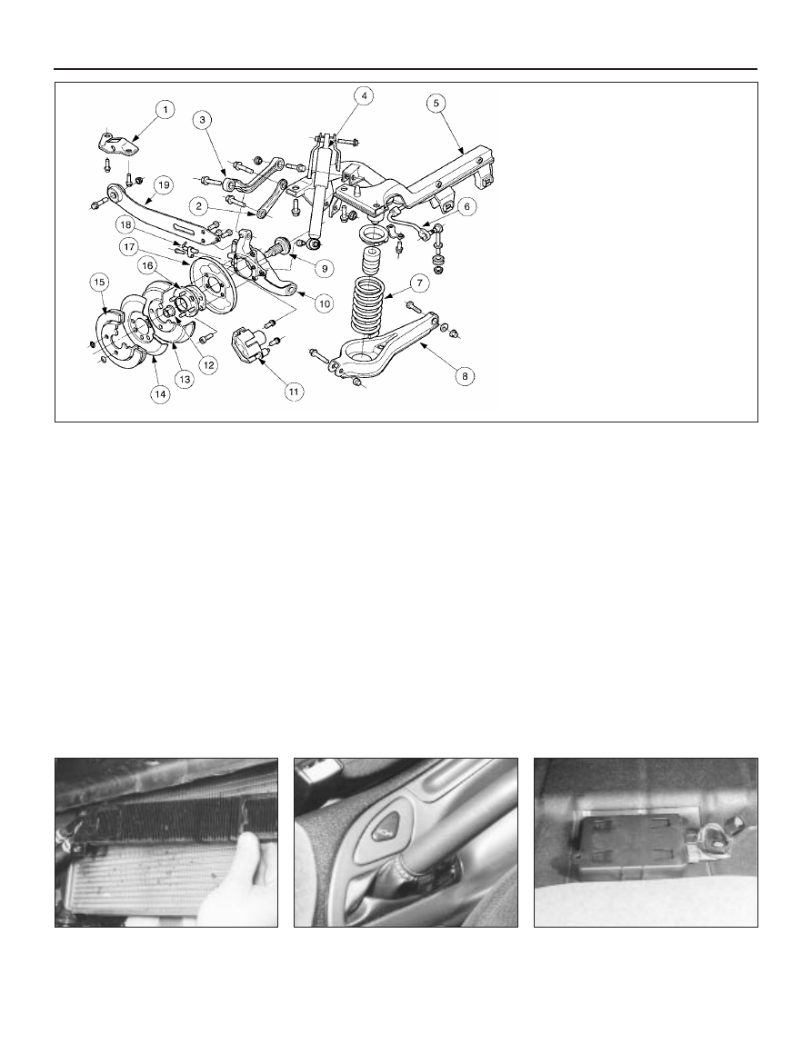
1.3  Rear suspension components on

Estate models

1  Tie-bar bracket
2  Short front lower arm
3  Long front upper arm
4  Shock absorber
5  Crossmember
6  Anti-roll bar
7  Coil spring
8  Rear lower arm
9  Stub axle (part of hub and bearing 

assembly)

10  Knuckle
11  Brake caliper (disc brake models)
12  Hub nut
13  Brake drum
14  Splash guard (disc brake models)
15  Brake disc
16  Hub and bearing assembly
17  Backplate (drum brake models)
18  ABS wheel sensor
19  Tie-bar

Since most of the procedures dealt with in

this Chapter involve jacking up the vehicle
and working underneath it, a good pair of axle
stands will be needed. A hydraulic trolley jack
is the preferred type of jack to lift the vehicle,
and it can also be used to support certain
components during removal and refitting
operations. 

Warning: Never, under any
circumstances, rely on a jack to
support the vehicle while working

beneath it. When jacking up the vehicle, do
not lift or support it beneath the front or
rear subframes.

Removal

Apply the handbrake. Remove the wheel
cover from the relevant front wheel, and
loosen (but do not remove) the driveshaft/hub
nut. This nut is very tight.
Loosen the front wheel nuts, jack up the
front of the vehicle and support it on axle
stands. Remove the front wheel.
Extract the split pin from the track rod end
balljoint nut. Unscrew the nut, and detach the
rod from the arm on the steering knuckle
using a conventional balljoint removal tool.
Take care not to damage the balljoint seal.
Remove the ABS sensor (when fitted) as
described in Chapter 9.
Remove the brake caliper and brake disc as
described in Chapter 9, but do not disconnect
the flexible hose from the caliper. Suspend
the caliper from a suitable point under the
wheel arch, taking care not to strain the hose.
Unscrew and remove the driveshaft/hub
nut. Note that the nut is of special laminated
design, and should only be re-used a
maximum of 5 times. (It is a good idea to file a
small notch on the nut every time it is
removed.) Obtain a new nut if necessary.
Note which way round the lower arm
balljoint clamp bolt is fitted, then unscrew and
remove it from the knuckle assembly. Lever
the balljoint down from the knuckle; if it is
tight, prise the clamp open using a large flat-
bladed tool. Take care not to damage the
balljoint seal during the separation procedure.
Unscrew and remove the pinch-bolt
securing the steering knuckle assembly to the
front suspension strut, noting which way
round it is fitted. Prise open the clamp using a
wedge-shaped tool, and release the knuckle
from the strut. If necessary, tap the knuckle
downwards with a soft-headed mallet to
separate the two components. Support the
knuckle on an axle stand.
Pull the steering knuckle and hub assembly
from the driveshaft splines. If it is tight,
connect a universal puller to the hub flange,
and withdraw it from the driveshaft. When the
driveshaft is free, support it on an axle stand,
or suspend it from a suitable point under the

wheel arch, making sure that the inner
constant velocity joint is not turned through
more than 18°. (Damage may occur if the joint
is turned through too great an angle.)

Refitting

10 Lift the steering knuckle and hub
assembly onto the driveshaft splines, and
support the assembly on an axle stand.
11 Locate the assembly on the front
suspension strut. Insert the pinch-bolt with its
head facing forwards. Fit the nut and tighten it
to the specified torque.
12 Refit the lower arm balljoint to the knuckle
assembly, and insert the clamp bolt with its
head facing forwards. Refit the nut and tighten
it to the specified torque.
13 Refit the driveshaft/hub nut, and tighten it
moderately at this stage. Final tightening of
the nut is made with the vehicle lowered to the
ground.
14 Refit the brake caliper and brake disc as
described in Chapter 9.
15 Where fitted, refit the ABS sensor as
described in Chapter 9.
16 Reconnect the track rod end balljoint to
the steering arm, and tighten the nut to the
specified torque. Check that the split pin
holes are aligned; if necessary, turn the nut to
the nearest alignment, making sure that the
torque wrench setting is still within the
specified range. Insert a new split pin, and
bend it back to secure.
17 Refit the front wheel, and lower the
vehicle to the ground. Tighten the wheel nuts
to the specified torque.
18 Tighten the driveshaft/hub nut to the
specified torque, and refit the wheel cover.

Inspection

The front hub bearings are non-adjustable,
and are supplied already greased.
To check the bearings for excessive wear,
apply the handbrake, jack up the front of the
vehicle and support it on axle stands.
Grip the front wheel at top and bottom, and
attempt to rock it. If excessive movement is
noted, it may be that the hub bearings are
worn. Do not confuse wear in the driveshaft
outer joint or front suspension lower arm
balljoint with wear in the bearings. Hub
bearing wear will show up as roughness or
vibration when the wheel is spun; it will also
be noticeable as a rumbling or growling noise
when driving.

Renewal

Remove the steering knuckle and hub
assembly as described in Section 2.
The hub must now be removed from the
bearing inner races. It is preferable to use a
press to do this, but it is possible to drive out

the hub using a length of metal tube of
suitable diameter (see illustration).
Part of the inner race will remain on the hub,
and this should be removed using a puller.
Note that if this procedure is being used to
renew the hub only (ie it is not intended to
renew the bearings), then it is important to
check the condition of the bearing balls and
races, to see if they are fit for re-use. It is
difficult to be sure that no damage has
occurred, especially if makeshift methods
have been used during removal; in practice, it
is probably false economy not to renew the
bearings in any case, having got this far.
Using circlip pliers, extract the inner and
outer circlips securing the hub bearing in the
steering knuckle (see illustration).
Press or drive out the bearing, using a
length of metal tubing of diameter slightly less
than the bearing outer race.
10 Clean the bearing seating faces in the
steering knuckle.

3 Front hub and bearings -

inspection and renewal

2 Steering knuckle and hub

assembly 
removal and refitting

Suspension and steering systems  10•5

10

3.5  Front hub and bearing

1  Hub

4  Stub axle

2  Double-row ball-bearing 5  Steering knuckle
3  Circlips

6  ABS sensor

3.8  Front wheel bearing retaining circlips

(arrowed)

11 Locate one of the circlips in the outer
groove of the knuckle.
12 Press or drive the new bearing into the
knuckle until it contacts the circlip, using a
length of metal tube of diameter slightly less
than the outer race. Do not apply any
pressure to the inner race.
13 Locate the remaining circlip in the inner
groove of the knuckle.
14 Support the inner race on a length of
metal tube, then press or drive the hub fully
into the bearing.
15 Refit the steering knuckle and hub
assembly as described in Section 2.

Removal

Apply the handbrake, then jack up the front
of the vehicle and support it on axle stands.
Remove the appropriate front wheel.
Unbolt the brake hose support bracket from
the front of the suspension strut (see
illustration)
.
Remove the brake caliper as described in
Chapter 9, but do not disconnect the flexible
hydraulic hose from the caliper. Suspend the
caliper from a suitable point under the wheel
arch, taking care not to strain the hose.
Extract the split pin from the track rod end
balljoint nut. Unscrew the nut, and detach the
rod from the arm on the steering knuckle

using a conventional balljoint removal tool.
Take care not to damage the balljoint seal.
Remove the ABS sensor (when fitted) from
the steering knuckle, as described in Chapter 9.
Remove the clip securing the driveshaft
inner gaiter to the inner CV joint. Disconnect
the gaiter from the CV joint housing.
Remove the nut and disconnect the anti-roll
bar link from the strut. Note that, on models
fitted with ABS, the ABS wheel sensor wiring
support bracket is located beneath the nut
(see illustration).
Note which way round the lower arm
balljoint clamp bolt is fitted, then unscrew and
remove it from the knuckle assembly. Lever
the balljoint down from the knuckle; if it is
tight, prise the clamp open carefully using a
large flat-bladed tool. Take care not to
damage the balljoint seal during the
separation procedure.
Where applicable, disconnect the adaptive
damping wiring multi-plug at the strut, and
unclip the wire.
10 Support the strut and steering knuckle on
an axle stand. Working inside the engine
compartment, remove the strut cap (if fitted).
Unscrew and remove the front suspension
strut upper mounting nut, holding the piston
rod stationary with an 8 mm Allen key (see
illustration)
.
11 Lower the suspension strut, together with
the driveshaft and steering knuckle, from
under the wheel arch, withdrawing the tripod
on the inner end of the driveshaft from the CV
joint housing.

12 Unscrew and remove the pinch-bolt
securing the steering knuckle assembly to the
front suspension strut, noting which way
round it is fitted. Prise open the clamp using a
wedge-shaped tool, and release the knuckle
from the strut (see illustrations).

Refitting

13 With the clamp prised open, locate the
front suspension strut on the steering knuckle,
and refit the pinch-bolt with its head facing
forwards. Tighten the bolt to the specified
torque.
14 Locate the suspension strut (together with
the driveshaft and steering knuckle) in its
upper mounting, and loosely screw on the
nut.
15 Locate the tripod on the inner end of the
driveshaft in the CV joint housing, then
manipulate the gaiter onto the housing, and fit
a new clip.
16 Where applicable, reconnect the adaptive
damping multi-plug, and fit the wire in the clip.
17 Locate the lower arm balljoint fully in the
bottom of the steering knuckle. Refit the
clamp bolt and tighten it to the specified
torque.
18 Reconnect the anti-roll bar link to the
strut, and tighten the nut to the specified
torque. On models fitted with ABS, do not
forget to locate the sensor wiring support
bracket beneath the nut.
19 Where fitted, refit the ABS sensor as
described in Chapter 9.
20 Refit the track rod end balljoint to the
steering knuckle, and tighten the nut to the
specified torque. Check that the split pin
holes are aligned; if necessary, turn the nut to
the nearest alignment, making sure that the
torque wrench setting is still within the
specified range. Insert a new split pin, and
bend it back to secure.
21 Refit the brake caliper as described in
Chapter 9.
22 Refit the brake hose support bracket to
the strut, and tighten the bolt.
23 Refit the wheel, and lower the vehicle to
the ground. Tighten the wheel nuts to the
specified torque.
24 Tighten the suspension strut upper
mounting nut to the specified torque, while

4 Front suspension strut -

removal and refitting

10•6 Suspension and steering systems

4.2  Removing the brake hose support

bracket from the front of the front

suspension strut

4.7  Removing the anti-roll bar link and

ABS sensor wiring bracket

4.10  Front suspension strut upper

mounting nut

4.12A  Steering knuckle-to-strut pinch-bolt

4.12B  Releasing the knuckle from the strut

holding the piston rod with an 8 mm Allen key.
If the adaptor needed to do this is not
available, the nut can be tightened initially
with a ring spanner while the piston rod is
held. Final tightening can then be carried out
using a torque wrench and a conventional
socket (see illustration).

Warning: Before attempting to
dismantle the front suspension
strut, a tool to hold the coil spring
in compression must be obtained.

Do not attempt to use makeshift methods.
Uncontrolled release of the spring could
cause damage and personal injury. Use a
high-quality spring compressor, and
carefully follow the tool manufacturer’s
manuals provided with it. After removing
the coil spring with the compressor still
fitted, place it in a safe, isolated area.

If the front suspension struts exhibit signs
of wear (leaking fluid, loss of damping
capability, sagging or cracked coil springs)
then they should be dismantled and
overhauled as necessary. The struts
themselves cannot be serviced, and should
be renewed if faulty, but the springs and
related components can be renewed. To
maintain balanced characteristics on both
sides of the vehicle, the components on both
sides should be renewed at the same time.
With the strut removed from the vehicle, clean

away all external dirt, then mount it in a vice.
Fit the coil spring compressor tools
(ensuring that they are fully engaged), and
compress the spring until all tension is relieved
from the upper mounting (see illustration).
Hold the strut piston with an Allen key, and

unscrew the thrust bearing retaining nut with a
ring spanner (see illustration).
Withdraw the top mounting, thrust bearing,
upper spring seat and spring, followed by the
gaiter and the bump stop (see illustrations).
If a new spring is to be fitted, the original

5 Front suspension strut -

overhaul

Suspension and steering systems  10•7

10

5.5A  Front suspension strut components

1  Cap
2  Nut
3  Retainer
4  Nut
5  Top mounting
6  Thrust bearing

7  Upper spring seat
8  Spring
9  Bump stop

10  Gaiter
11  Lower spring seat

12  Strut
13  Steering knuckle
14  Clamp bolt
15  Solenoid valve for models 

with adaptive damping

4.24  Final tightening of the front

suspension strut upper mounting nut

5.3  Coil spring compressor tools fitted to

the coil spring

5.4  Unscrewing the nut from the top of the

strut

5.5B  Removing the top mounting from the strut

5.5C  Removing the gaiter

5.5D  Removing the bump stop


Content   ..  104  105  106  107   ..