Ford Mondeo (petrol engines). Manual - part 105
 

  Index      Ford     Ford Mondeo - service and repair manual (petrol engines)


Search            


Content   ..  103  104  105  106   ..


Ford Mondeo (petrol engines). Manual - part 105


Refitting and adjustment

With the switch removed, reset it by fully
extending its plunger.
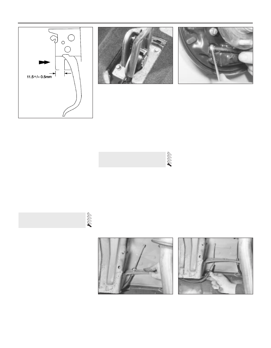
Depress the brake pedal until the distance
between the pedal and mounting bracket is as
shown (see illustration).
Hold the pedal in this position, and refit the
stop-light switch to the mounting bracket .
With the switch securely clipped in position,
release the brake pedal, and gently pull it fully
back to the at-rest position. This will
automatically set the adjustment of the stop-
light switch.
reconnect the wiring connector and the
battery, and check the operation of the switch
prior to refitting the lower facia panel (Chapter 11).

Removal

Raise the front and rear of the vehicle, and
support it on axle stands. Fully release the
handbrake lever.
Remove the centre console as described in
Chapter 11.
Working beneath the vehicle, release the
exhaust system from the rubber mountings.
Lower the exhaust system as far as possible,
supporting it on blocks or more axle stands.
Detach the exhaust heat shield from the
underbody.
Unhook the secondary (rear) handbrake
cables from the equaliser bar.
Working inside the vehicle, unscrew and
remove the two mounting bolts securing the
handbrake lever to the floor (see illustration).

Turn the handbrake lever upsidedown, then
disconnect the primary cable end from the
segment.
Withdraw the handbrake from inside the
vehicle.

Refitting

Refitting is a reversal of the removal
procedure, making sure that the primary cable
is correctly located in the segment. Check the
operation of the handbrake before returning
the vehicle to normal service.

Removal

Primary (front)

Remove the handbrake lever as described
in Section 26.
Prise the grommet from the underbody,
and withdraw the cable from beneath the
vehicle.

Secondary (rear)

Chock the front wheels, and engage 1st
gear (or “P”). Jack up the rear of the vehicle
and support it on axle stands. Fully release
the handbrake lever.
Remove the relevant rear wheel.

Working beneath the vehicle, release the
exhaust system from the rubber mountings.
Lower the exhaust system as far as possible,
supporting it on blocks or more axle stands.
Unbolt the exhaust heat shield from the
underbody.
Unhook the relevant cable from the
equaliser bar.
On drum brake models, remove the rear
brake shoes on the relevant side as described
in Section 6, then remove the outer cable from
the backplate by compressing the three
retaining lugs (use a suitable ring spanner)
and pushing the cable through (see
illustration)
.
On disc brake models, unhook the end of
the cable from the handbrake operating arm
on the rear caliper.
10 Release the lugs securing the outer cable
to the underbody brackets, then release the
cable from the clips, and withdraw it from
under the vehicle (see illustrations).

Refitting

All cables

11 Refitting is a reversal of the removal
procedure, but make sure that the cable end
fittings are correctly located. Check the
operation of the handbrake before returning
the vehicle to normal service.

27 Handbrake cables -

removal and refitting

26 Handbrake lever 

removal and refitting

9•16 Braking system

25.6  To ensure correct adjustment,

position the brake pedal as shown prior to

refitting the switch to its mounting bracket

26.6  Handbrake lever mounting bolts

27.8  Using a ring spanner to compress the

retaining lugs securing the outer cable to

the backplate

27.10A  Release the lugs using a ring

spanner . . .

27.10B  . . . and remove the outer cable

from the underbody brackets

Chapter 10 Suspension and steering systems

Front anti-roll bar and links - removal and refitting  . . . . . . . . . . . . . .

6

Front hub and bearings - inspection and renewal  . . . . . . . . . . . . . .

3

Front suspension lower arm - removal, overhaul and refitting  . . . . .

7

Front suspension lower arm balljoint - renewal  . . . . . . . . . . . . . . . .

8

Front suspension strut - overhaul  . . . . . . . . . . . . . . . . . . . . . . . . . . .

5

Front suspension strut - removal and refitting  . . . . . . . . . . . . . . . . .

4

General information . . . . . . . . . . . . . . . . . . . . . . . . . . . . . . . . . . . . . .

1

Power steering fluid level check  . . . . . . . . . . . . . . . . .

See Chapter 1

Power steering gear (all except left-hand-drive models 

with ABS) - removal and refitting . . . . . . . . . . . . . . . . . . . . . . . . . . 30

Power steering gear (left-hand-drive models with ABS) - 

removal and refitting  . . . . . . . . . . . . . . . . . . . . . . . . . . . . . . . . . . . 31

Power steering gear rubber gaiters - renewal  . . . . . . . . . . . . . . . . . . 32
Power steering hydraulic system - bleeding  . . . . . . . . . . . . . . . . . . . 33
Power steering pump - removal and refitting  . . . . . . . . . . . . . . . . . . 34
Rear anti-roll bar and links (Estate models) - removal and refitting  . 20
Rear anti-roll bar and links (Saloon/Hatchback models) - 

removal and refitting  . . . . . . . . . . . . . . . . . . . . . . . . . . . . . . . . . . . 13

Rear coil spring (Estate models) - removal and refitting  . . . . . . . . . . 21
Rear hub and bearings (Estate models) - inspection and renewal  . . 17
Rear hub and bearings (Saloon/Hatchback models) - 

inspection and renewal  . . . . . . . . . . . . . . . . . . . . . . . . . . . . . . . . .

9

Rear shock absorber (Estate models) - removal, testing and refitting . 19
Rear suspension crossmember (Estate models) - removal 

and refitting  . . . . . . . . . . . . . . . . . . . . . . . . . . . . . . . . . . . . . . . . . . 26

Rear suspension crossmember (Saloon/Hatchback models) - 

removal and refitting  . . . . . . . . . . . . . . . . . . . . . . . . . . . . . . . . . . . 16

Rear suspension front lower arm (Estate models) - removal 

and refitting  . . . . . . . . . . . . . . . . . . . . . . . . . . . . . . . . . . . . . . . . . . 23

Rear suspension knuckle (Estate models) - removal and refitting  . . 18
Rear suspension knuckle (Saloon/Hatchback models) - removal 

and refitting  . . . . . . . . . . . . . . . . . . . . . . . . . . . . . . . . . . . . . . . . . . 10

Rear suspension lower arms (Saloon/Hatchback models) - 

removal and refitting  . . . . . . . . . . . . . . . . . . . . . . . . . . . . . . . . . . . 14

Rear suspension rear lower arm (Estate models) - removal 

and refitting  . . . . . . . . . . . . . . . . . . . . . . . . . . . . . . . . . . . . . . . . . . 22

Rear suspension strut (Saloon/Hatchback models) - overhaul . . . . . 12
Rear suspension strut (Saloon/Hatchback models) - 

removal and refitting  . . . . . . . . . . . . . . . . . . . . . . . . . . . . . . . . . . . 11

Rear suspension tie-bar (Estate models) - removal and refitting  . . . 25
Rear suspension tie-bar (Saloon/Hatchback models) - 

removal and refitting  . . . . . . . . . . . . . . . . . . . . . . . . . . . . . . . . . . . 15

Rear suspension upper arm (Estate models) - removal 

and refitting  . . . . . . . . . . . . . . . . . . . . . . . . . . . . . . . . . . . . . . . . . . 24

Steering column - removal, inspection and refitting  . . . . . . . . . . . . . 28
Steering column flexible coupling - removal and refitting . . . . . . . . . 29
Steering knuckle and hub assembly - removal and refitting  . . . . . . .

2

Steering, suspension and wheel check  . . . . . . . . . . . .

See Chapter 1

Steering wheel - removal and refitting  . . . . . . . . . . . . . . . . . . . . . . . 27
Track rod end - renewal  . . . . . . . . . . . . . . . . . . . . . . . . . . . . . . . . . . 35
Tyre condition and tyre pressure checks . . . . . . . . . . .

See Chapter 1

Wheel alignment and steering angles - general information  . . . . . . . 36

Front wheel alignment

Toe setting:

Tolerance allowed before resetting required . . . . . . . . . . . . . . . . . . . .

0.5 mm to 3.5 mm toe-out (0°05’ to 0°35’ toe-out)

Adjustment setting (if required)  . . . . . . . . . . . . . . . . . . . . . . . . . . . . . .

2.0 mm ± 1.0 mm toe-out (0°20’ ± 0°10’ toe-out)

Rear wheel alignment

Toe setting:

Tolerance allowed before resetting required:

Saloon/Hatchback . . . . . . . . . . . . . . . . . . . . . . . . . . . . . . . . . . . . . .

3.9 mm toe-in to 0.1 mm toe-out (0°38’ toe-in to 0°02’ toe-out)

Estate . . . . . . . . . . . . . . . . . . . . . . . . . . . . . . . . . . . . . . . . . . . . . . . .

2.7 mm toe-in to 1.3 mm toe-out (0°27’ toe-in to 0°13’ toe-out)

Adjustment setting (if required):

Saloon/Hatchback . . . . . . . . . . . . . . . . . . . . . . . . . . . . . . . . . . . . . .

1.9 mm ± 1.2 mm toe-in (0°18’ ± 0°12’ toe-in)

Estate . . . . . . . . . . . . . . . . . . . . . . . . . . . . . . . . . . . . . . . . . . . . . . . .

0.7 mm ± 1.2 mm toe-in (0°07’ ± 0°12’ toe-in)

Roadwheels and tyres

Wheel sizes:

Steel  . . . . . . . . . . . . . . . . . . . . . . . . . . . . . . . . . . . . . . . . . . . . . . . . . .

14 x 5 1/2

Alloy . . . . . . . . . . . . . . . . . . . . . . . . . . . . . . . . . . . . . . . . . . . . . . . . . . .

14 x 5 1/2 or 15 x 6

Tyre sizes:

Wheel size 14 x 5 1/2  . . . . . . . . . . . . . . . . . . . . . . . . . . . . . . . . . . . . .

185/65/14 or 195/60VR/14

Wheel size 15 x 6  . . . . . . . . . . . . . . . . . . . . . . . . . . . . . . . . . . . . . . . .

205/55VR/15

Tyre pressures . . . . . . . . . . . . . . . . . . . . . . . . . . . . . . . . . . . . . . . . . . . . .

See Chapter 1 Specifications

10•1

Easy, suitable for
novice with little
experience

Fairly easy, suitable
for beginner with
some experience

Fairly difficult, suitable
for competent DIY
mechanic

Difficult, suitable for
experienced  DIY
mechanic

Very difficult,
suitable for expert DIY
or  professional

Degrees of difficulty

Specifications

Contents

10

Torque wrench settings

Nm

lbf ft

Front suspension

Front subframe  . . . . . . . . . . . . . . . . . . . . . . . . . . . . . . . . . . . . . . . . . . . .

110 to 150

81 to 111

Lower arm balljoint to lower arm (service replacement, bolted on)  . . . .

58

43

Lower arm balljoint-to-steering  knuckle clamp bolt  . . . . . . . . . . . . . . .

48 to 60

35 to 44

Lower arm to subframe:

Stage 1 (used components)  . . . . . . . . . . . . . . . . . . . . . . . . . . . . . . . .

50

37

Stage 1 (new components)  . . . . . . . . . . . . . . . . . . . . . . . . . . . . . . . . .

70

52

Stage 2  . . . . . . . . . . . . . . . . . . . . . . . . . . . . . . . . . . . . . . . . . . . . . . . .

Slacken completely

Stage 3  . . . . . . . . . . . . . . . . . . . . . . . . . . . . . . . . . . . . . . . . . . . . . . . .

50

37

Stage 4  . . . . . . . . . . . . . . . . . . . . . . . . . . . . . . . . . . . . . . . . . . . . . . . .

Tighten through further 90°

Anti-roll bar  . . . . . . . . . . . . . . . . . . . . . . . . . . . . . . . . . . . . . . . . . . . . . . .

24

18

Anti-roll bar link  . . . . . . . . . . . . . . . . . . . . . . . . . . . . . . . . . . . . . . . . . . . .

41 to 58

30 to 43

Suspension strut-to-steering knuckle pinch-bolt  . . . . . . . . . . . . . . . . . .

84

62

Suspension strut upper mounting nut . . . . . . . . . . . . . . . . . . . . . . . . . . .

46

34

Suspension strut thrust bearing retaining nut  . . . . . . . . . . . . . . . . . . . . .

59

44

Driveshaft/hub retaining nut  . . . . . . . . . . . . . . . . . . . . . . . . . . . . . . . . . .

340

251

Rear suspension (Saloon/Hatchback)

Crossmember mounting bolts  . . . . . . . . . . . . . . . . . . . . . . . . . . . . . . . .

102 to 138

75 to 102

Front lower arm to knuckle and to crossmember  . . . . . . . . . . . . . . . . . .

70 to 98

52 to 72

Rear lower arm to knuckle  . . . . . . . . . . . . . . . . . . . . . . . . . . . . . . . . . . .

102 to 138

75 to 102

Rear lower arm to crossmember . . . . . . . . . . . . . . . . . . . . . . . . . . . . . . .

70 to 98

52 to 72

Anti-roll bar  . . . . . . . . . . . . . . . . . . . . . . . . . . . . . . . . . . . . . . . . . . . . . . .

19 to 26

14 to 19

Anti-roll bar link  . . . . . . . . . . . . . . . . . . . . . . . . . . . . . . . . . . . . . . . . . . . .

30 to 40

22 to 30

Suspension strut to knuckle  . . . . . . . . . . . . . . . . . . . . . . . . . . . . . . . . . .

70 to 98

52 to 72

Drum brake backplate . . . . . . . . . . . . . . . . . . . . . . . . . . . . . . . . . . . . . . .

45 to 54

33 to 40

Disc brake splash shield  . . . . . . . . . . . . . . . . . . . . . . . . . . . . . . . . . . . . .

90

66

Hub nut  . . . . . . . . . . . . . . . . . . . . . . . . . . . . . . . . . . . . . . . . . . . . . . . . . .

290

181

Tie-bar and tie-bar bracket  . . . . . . . . . . . . . . . . . . . . . . . . . . . . . . . . . . .

102 to 138

75 to 102

Suspension strut upper mounting bolts  . . . . . . . . . . . . . . . . . . . . . . . . .

23 to 30

17 to 22

Suspension strut upper nut . . . . . . . . . . . . . . . . . . . . . . . . . . . . . . . . . . .

41 to 58

30 to 43

Rear suspension (Estate)

Same as for Saloon/Hatchback, except for the following.
Crossmember mounting bolts  . . . . . . . . . . . . . . . . . . . . . . . . . . . . . . . .

120

89

Front lower arm to knuckle and to crossmember  . . . . . . . . . . . . . . . . . .

120

89

Upper arm to knuckle  . . . . . . . . . . . . . . . . . . . . . . . . . . . . . . . . . . . . . . .

120

89

Upper arm to crossmember  . . . . . . . . . . . . . . . . . . . . . . . . . . . . . . . . . .

84

62

Rear lower arm to knuckle and to crossmember  . . . . . . . . . . . . . . . . . .

84

62

Anti-roll bar  . . . . . . . . . . . . . . . . . . . . . . . . . . . . . . . . . . . . . . . . . . . . . . .

25

19

Anti-roll bar link  . . . . . . . . . . . . . . . . . . . . . . . . . . . . . . . . . . . . . . . . . . . .

35

26

Hub assembly-to-knuckle retaining bolts  . . . . . . . . . . . . . . . . . . . . . . . .

65

48

Tie-bar to bracket  . . . . . . . . . . . . . . . . . . . . . . . . . . . . . . . . . . . . . . . . . .

120

89

Tie-bar bracket to underbody  . . . . . . . . . . . . . . . . . . . . . . . . . . . . . . . . .

120

89

Tie-bar to knuckle  . . . . . . . . . . . . . . . . . . . . . . . . . . . . . . . . . . . . . . . . . .

84

62

Shock absorber upper mounting bolt  . . . . . . . . . . . . . . . . . . . . . . . . . . .

84

62

Shock absorber lower mounting bolt  . . . . . . . . . . . . . . . . . . . . . . . . . . .

120

89

Steering

Steering gear mounting bolts  . . . . . . . . . . . . . . . . . . . . . . . . . . . . . . . . .

114 to 159

84 to 117

Track rod end to steering knuckle  . . . . . . . . . . . . . . . . . . . . . . . . . . . . .

25 to 30

18 to 22

Track rod end locknut  . . . . . . . . . . . . . . . . . . . . . . . . . . . . . . . . . . . . . . .

34 to 47

25 to 35

Steering wheel . . . . . . . . . . . . . . . . . . . . . . . . . . . . . . . . . . . . . . . . . . . . .

45 to 55

33 to 41

Flexible coupling-to-pinion shaft clamp bolt  . . . . . . . . . . . . . . . . . . . . .

23 to 32

17 to 24

Power steering pipe unions to valve body  . . . . . . . . . . . . . . . . . . . . . . .

27 to 35

20 to 26

Steering column-to-coupling clamp bolt  . . . . . . . . . . . . . . . . . . . . . . . .

20 to 27

14 to 20

Steering column mounting bolts  . . . . . . . . . . . . . . . . . . . . . . . . . . . . . . .

20 to 27

14 to 20

Steering pump mounting bolts  . . . . . . . . . . . . . . . . . . . . . . . . . . . . . . . .

21 to 28

15 to 21

Steering pump pressure line  . . . . . . . . . . . . . . . . . . . . . . . . . . . . . . . . . .

57 to 73

42 to 54

Roadwheel nuts . . . . . . . . . . . . . . . . . . . . . . . . . . . . . . . . . . . . . . . . . . .

85

63

10•2 Suspension and steering systems

The independent front suspension is of

MacPherson strut type, incorporating coil
springs, integral telescopic shock absorbers,
and an anti-roll bar. The struts are attached to
steering knuckles at their lower ends, and the
knuckles are in turn attached to the lower
suspension arm by balljoints. The anti-roll bar
is bolted to the rear of the subframe, and is
connected to the front suspension struts by
links (see illustration).

On Saloon/Hatchback models, the

independent rear suspension is of
“Quadralink” type, having four mounting
points on each side of the vehicle. The two
lower arms are attached to the rear
suspension knuckle at their outer ends, and to
the rear crossmember at their inner ends. A
tie-bar, located between the bottom of the
knuckle and the floor, counteracts braking
and acceleration forces on each side (see
illustration)
.

On Estate models, the independent rear

suspension is of “SLA” (Short and Long Arm)
type. This allows a larger load area, since
there are no suspension points projecting into
the luggage area. There are three side arms
on each side: one forged upper arm, and two

1 General information

Suspension and steering systems  10•3

10

1.1  Front suspension components

1  MacPherson strut
2  Steering knuckle
3  Lower arm

4  Vertical silent bush on 

lower arm

5  Anti-roll bar

6  Front subframe
7  Front subframe rubber bush
8  Rear subframe rubber bush

1.2  Rear suspension components on

Saloon/Hatchback models

1  Wheel housing
2  Upper mounting bracket and coil spring seat
3  Strut
4  Solenoid valve for adaptive damping
5  Rear suspension crossmember
6  Eccentric bolt for rear toe setting
7  Anti-roll bar
8  Link
9  Front lower arm
10  Rear lower arm
11  Knuckle (drum brake models)
12  ABS wheel sensor 

(drum brake models)

13  Tie-bar
14  Backplate
15  Hub and bearing assembly
16  Hub nut
17  Grease cap
18  Brake drum
19  Tie-bar mounting bracket
20  Brake disc
21  Splash shield (disc brake models)
22  Brake caliper (disc brake models)
23  Knuckle (disc brake models)
24  ABS wheel sensor (disc brake models)


Content   ..  103  104  105  106   ..