Ford Mondeo (petrol engines). Manual - part 103
 

  Index      Ford     Ford Mondeo - service and repair manual (petrol engines)


Search            


Content   ..  101  102  103  104   ..


Ford Mondeo (petrol engines). Manual - part 103


With the drum in position, refit the wheel,
then carry out the renewal procedure on the
remaining rear brake.
Lower the vehicle to the ground, and
tighten the wheel nuts.
Depress the brake pedal several times, in
order to operate the self-adjusting mechanism
and set the shoes at their normal operating
position.
Make several forward and reverse stops,
and operate the handbrake fully two or three
times. Give the vehicle a road test, to make
sure that the brakes are functioning correctly,
and to bed-in the new linings to the contours
of the disc. Remember that the new linings
will not give full braking efficiency until they
have bedded-in.

Note: Before starting work, check on the
availability of parts (overhaul kit of seals). Also
bear in mind that if the brake shoes have been
contaminated by fluid leaking from the wheel
cylinder, they must be renewed. In principle,
the shoes on BOTH sides of the vehicle must
be renewed, even if they are only
contaminated on one side.

Removal

Remove the brake drum as described in
Section 5.
Minimise fluid loss either by removing the
master cylinder reservoir cap, and then
tightening it down onto a piece of polythene
to obtain an airtight seal, or by using a brake
hose clamp, a G-clamp, or similar tool, to
clamp the flexible hose at the nearest
convenient point to the wheel cylinder.
Pull the brake shoes apart at their top ends,
so that they are just clear of the wheel
cylinder. The automatic adjuster will hold the
shoes in this position, so that the cylinder can
be withdrawn.
Wipe away all traces of dirt around the
hydraulic union at the rear of the wheel
cylinder, then undo the union nut.

Unscrew the two bolts securing the wheel
cylinder to the backplate (see illustration).
Withdraw the wheel cylinder from the
backplate so that it is clear of the brake
shoes. Plug the open hydraulic unions, to
prevent the entry of dirt, and to minimise
further fluid loss whilst the cylinder is
detached.

Overhaul

Clean the external surfaces of the cylinder,
and unscrew the bleed screw.
Carefully prise off the dust cover from each
end of the cylinder.
Tap the wheel cylinder on a block of wood
to eject the pistons and seals, keeping them
identified for location. Finally remove the
spring.
10 Clean the pistons and the cylinder by
washing in methylated spirit or fresh hydraulic
fluid. Do not use petrol, paraffin or any other
mineral-based fluid. Remove and discard the
old seals, noting which way round they are
fitted.
11 Examine the surfaces of the pistons and
the cylinder bores, and look for any signs of
rust or scoring. If such damage is evident, the
complete wheel cylinder must be renewed.
12 Reassemble by lubricating the first piston
in clean hydraulic fluid, then manipulating a
new seal into position, so that its raised lip
faces away from the brake shoe bearing face
of the piston.
13 Insert the piston into the cylinder. As the
seal enters the bore, twist the piston back and
forth so that the seal lip is not trapped.
14 Insert the spring, then refit the remaining
piston and seal, again making sure that the
seal lip is not trapped as it enters the bore.
15 Fit new dust covers to the grooves in the
pistons and wheel cylinder body.
16 Refit the bleed screw.

Refitting

17 Wipe clean the backplate, and remove the
plug from the end of the hydraulic pipe. Fit the
cylinder onto the backplate, and screw in the
hydraulic union nut by hand, being careful not
to cross-thread it.

18 Tighten the mounting bolts, then fully
tighten the hydraulic union nut.
19 Retract the automatic brake adjuster
mechanism, so that the brake shoes engage
with the pistons of the wheel cylinder. To do
this, prise the shoes apart slightly, turn the
automatic adjuster to its minimum position,
and release the shoes.
20 Remove the clamp from the flexible brake
hose, or the polythene from the master
cylinder (as applicable).
21 Refit the brake drum with reference to
Section 5.
22 Bleed the brake hydraulic system as
described in Section 15. Providing suitable
precautions were taken to minimise loss of
fluid, it should only be necessary to bleed the
relevant rear brake.
23 Test the brakes carefully before returning
the vehicle to normal service.

Warning: Disc brake pads must
be renewed on BOTH rear wheels
at the same time - never renew
the pads on only one wheel, as

uneven braking may result. Although
genuine Ford linings are asbestos-free, the
dust created by wear of non-genuine pads
may contain asbestos, which is a health
hazard. Never blow it out with compressed
air, and don’t inhale any of it. DO NOT use
petroleum-based solvents to clean brake
parts; use brake cleaner or methylated
spirit only. DO NOT allow any brake fluid,
oil or grease to contact the brake pads or
disc.

Chock the front wheels, and engage 1st
gear (or “P”). Loosen the rear wheel nuts, jack
up the rear of the vehicle and support it on
axle stands.
Remove the rear wheels. Work on one
brake assembly at a time, using the
assembled brake for reference if necessary.
Inspect the rear brake disc as described in
Section 10.
Extract the spring clip, and pull out the
retaining pin securing the caliper to the carrier

8 Rear brake pads - renewal

7 Rear wheel cylinder 

removal, overhaul and refitting

9•8 Braking system

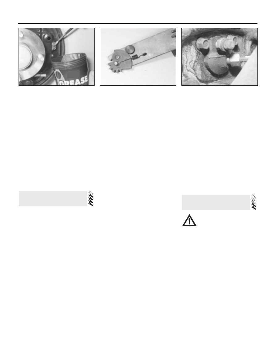
6.2N  Clean the backplate, and apply small

amounts of high-melting-point brake

grease to the brake shoe contact points.

Be careful not to get grease on any friction

surfaces

6.2O  Lubricate the sliding components of

the automatic adjuster with a little high-

melting-point brake grease, but leave the

serrations on the eccentric cam shown

here clean

7.5  Bolts securing the wheel cylinder to

the backplate. Hydraulic union nut and

bleed screw cover are also visible

bracket. Note that on Saloon and Hatchback
models, the pin is at the bottom of the caliper,
whereas on Estate models, it is at the top.
Swivel the caliper away from the carrier
bracket, to expose the brake pads (see
illustrations).
Disconnect the pad wear warning light wire
(when fitted) at the connector. Also unbolt the
brake hose bracket from the rear suspension
strut, to avoid straining the flexible hose.
If necessary, the caliper may be completely
removed by prising off the cap and
unscrewing the pivot guide bolt. Support the
caliper on an axle stand, or tie it to one side
with wire.
Remove the pads from the carrier bracket.
Brush all dust and dirt from the caliper,
pads and disc, but do not inhale it, as it may
be harmful to health. Scrape any corrosion
from the disc.
10 Before fitting the new pads, screw the
caliper piston fully into its bore, at the same
time pressing the piston fully to the bottom of
the bore. Proprietary tools are available for
this operation - at a pinch, it may be possible
to use long-nosed pliers engaged with the
cut-outs in the piston. Brake fluid will be
displaced into the master cylinder reservoir,
so check first that there is enough space to
accept the fluid. If necessary, syphon off
some of the fluid.
11 Fit the new pads using a reversal of the
removal procedure. On completion, firmly
depress the brake pedal a few times, to bring
the pads to their normal working position.
Check the level of the brake fluid in the
reservoir, and top-up if necessary.
12 Give the vehicle a road test, to make sure
that the brakes are functioning correctly, and
to bed-in the new linings to the contours of
the disc. Remember that full braking
efficiency will not be obtained until the new
linings have bedded-in.

Removal

Chock the front wheels, and engage 1st
gear (or “P”). Loosen the rear wheel nuts, jack
up the rear of the vehicle and support it on
axle stands. Remove the appropriate rear
wheel.
Fit a brake hose clamp to the flexible hose
leading to the rear brake caliper. This will
minimise brake fluid loss during subsequent
operations.
Loosen (but do not completely unscrew) the
union on the caliper end of the flexible hose.
Remove the rear brake pads, and free the
caliper as described in Section 8.
Disconnect the handbrake cable from the
caliper. On Saloon and Hatchback models,
the handbrake lever faces away from the
caliper, whereas on Estate models, it faces
towards the caliper (see illustrations).

Support the caliper and disconnect the
hydraulic hose, making sure that the hose is
not twisted or strained unduly. Once the
caliper is detached, place it to one side, and
plug the open hydraulic unions to keep dust
and dirt out.
If necessary, unbolt the carrier bracket from
the knuckle.

Overhaul

No overhaul procedures were available at
the time of writing, so check availability of
spares before dismantling the caliper. In
principle, the overhaul information given for
the front brake caliper will apply, noting that it
will be necessary to unscrew the piston from
the handbrake mechanism (see Section 8,
paragraph 10) before being able to expel the
piston from the caliper. On reassembly, push
the piston fully into the caliper, and screw it
back onto the handbrake mechanism. Do not
attempt to dismantle the handbrake
mechanism; if the mechanism is faulty, the
complete caliper assembly must be renewed.

Refitting

Refit the caliper, and where applicable the
carrier bracket, by reversing the removal
operations. Tighten the mounting bolts and
wheel nuts to the specified torque, and do not
forget to remove the brake hose clamp from
the flexible brake hose.

9 Rear brake caliper - removal,

overhaul and refitting

Braking system  9•9

9

9.5A  Rear brake caliper on

Saloon/Hatchback models (A) and Estate

models (B)

1  Caliper body
2  Frame
3  Brake pad spring clip
4  Handbrake cable lever facing away from 

caliper

5  Handbrake cable lever facing towards 

caliper

6  Bleed screw
7  Guide pin protective cap
8  Pad wear warning light connector
9  Flexible hydraulic hose connection

9.5B  Handbrake operation on the rear

brake caliper

1  Piston
2  Automatic adjusting screw
3  Spring washers
4  Cam
5  Handbrake cable lever

8.5A  Rear brake pad removal on Saloon

and Hatchback models

4  Brake caliper     5  Brake pads

8.5B  Rear brake pad removal on Estate

models

3  Brake caliper     5  Brake pads

10 Bleed the brake circuit according to the
procedure given in Section 15. Make sure
there are no leaks from the hose connections.
Test the brakes carefully before returning the
vehicle to normal service.

Refer to Section 4 (front disc inspection).

Once the rear caliper is removed, the
procedure is the same.

Removal

Disconnect the low fluid level warning light
multi-plug from the fluid reservoir filler cap
(see illustration). Unscrew and remove the
cap (note that the filler cap should not be
inverted). Draw off the hydraulic fluid from the
reservoir, using an old battery hydrometer or a
poultry baster. Do not syphon the fluid by
mouth; it is poisonous. Any brake fluid spilt on
paintwork should be washed off with clean
water, without delay - brake fluid is also a
highly-effective paint-stripper!
Identify the locations of each brake pipe on
the master cylinder. On non-ABS models,
there are four pipes; the two rear brake pipes
are attached to PCR (pressure-conscious

relief) valves on the master cylinder. On ABS
models, there are only two pipes, which lead
to the ABS hydraulic unit (see illustration).
Place rags beneath the master cylinder to
catch spilt hydraulic fluid.
Clean around the hydraulic union nuts.
Unscrew the nuts, and disconnect the
hydraulic lines from the master cylinder.
Unscrew the mounting nuts, and withdraw
the master cylinder from the studs on the front
of the servo unit. If the nuts are tight, a split
ring spanner should be used in preference to
an open-ended spanner. Plug or cap open
unions, to keep dust and dirt out.
Recover the gasket from the master cylinder.
If the master cylinder is faulty, it must be
renewed. At the time of writing, no overhaul
kits were available.

Refitting

Clean the contact surfaces of the master
cylinder and servo.
Locate a new gasket on the master cylinder.
10 Position the master cylinder on the studs
on the servo unit. Refit and tighten the nuts to
the specified torque.
11 Carefully insert the hydraulic lines in the
apertures in the master cylinder, then tighten

the union nuts. Make sure that the nuts enter
their threads correctly.
12 Fill the reservoir with fresh brake fluid.
13 Bleed the hydraulic system as described
in Section 15.
14 Refit the reservoir filler cap, and reconnect
the multi-plug for the low fluid level warning
light.
15 Test the brakes carefully before returning
the vehicle to normal service.

Removal

Working inside the vehicle, move the
driver’s seat fully to the rear, to allow
maximum working area.
Remove the ashtray, then unscrew the
screws and remove the lower facia panel.
Prise the hairpin clip from the right-hand
end of the pedal pivot shaft, and remove the
washer (see illustration).
Unscrew the nut securing the pedal
trunnion to the pushrod. The nut is located
near the top of the pedal (see illustrations).

12 Brake pedal 

removal and refitting

11 Master cylinder 

removal and refitting

10 Rear brake disc - inspection,

removal and refitting

9•10 Braking system

11.1  Brake fluid reservoir and low level

warning light multi-plug

11.2  Master cylinder connections

A  Non-ABS models
B  ABS models
1  Brake fluid reservoir
2  Master cylinder

3  PCR valves for rear brakes
4  Primary brake hydraulic circuit (front right/rear left)
5  Secondary brake hydraulic circuit (front left/rear right)

12.3  Removing the hairpin clip from the

right-hand end of the brake pedal pivot shaft

12.4A  Unscrew the nut securing the pedal

trunnion to the pushrod . . .

12.4B  . . . and remove the tube from the

pushrod

Press the pedal pivot shaft to the left,
through the mounting bracket, just far enough
to allow the pedal to be withdrawn. On
manual transmission models, leave the blue
nylon spacer (located between the clutch and
brake pedals) on the pivot shaft (see
illustration)
. On automatic transmission
models, the shaft can be removed completely
(see illustration).
With the pedal removed, prise out the
bushes from each side. If necessary, also
remove the pushrod trunnion and the rubber
pad. Renew the components as necessary
(see illustrations).

Refitting

Prior to refitting the pedal, apply a little
grease to the pivot shaft, pedal bushes and
trunnion.
Refitting is a reversal of the removal
procedure, but make sure that the pedal
bushes are correctly located, and that the
pedal shaft “D” section locates in the right-
hand side of the pedal bracket. Also make
sure that the hairpin clip is correctly
located.

Removal

Disconnect the battery negative (earth) lead
(Chapter 5, Section 1).
Remove the master cylinder and the
vacuum servo unit as described in Sec-
tions 11 and 16. If wished, the master cylinder
may be left attached to the servo unit.
Working inside the passenger
compartment, fold down the covering from
the front of both front footwells.
Have an assistant support the cross-link
assembly from inside the engine
compartment.
Unscrew and remove the nuts and bolts on
each side of the bulkhead, and remove the
link assembly from inside the engine
compartment. If necessary, have the assistant

hold the bolt heads from inside the engine
compartment while the nuts are being
loosened.
Clean the cross-link components, and
examine the bushes for wear. Renew the
bushes if necessary.

Refitting

Refitting is a reversal of the removal
procedure. Refer to Sections 11 and 16 when
refitting the master cylinder and vacuum servo
unit.

Inspection

Jack up the front and rear of the vehicle,
and support on axle stands.
Check for signs of leakage at the pipe
unions, then examine the flexible hoses for
signs of cracking, chafing and fraying.
The brake pipes should be examined
carefully for signs of dents, corrosion or other
damage. Corrosion should be scraped off,
and if the depth of pitting is significant, the
pipes renewed. This is particularly likely in
those areas underneath the vehicle body
where the pipes are exposed and
unprotected.
Renew any defective brake pipes and/or
hoses.

Removal

If a section of pipe or hose is to be
removed, loss of brake fluid can be reduced
by unscrewing the filler cap, and completely
sealing the top of the reservoir with cling film
or adhesive tape. Alternatively, the reservoir
can be emptied (see Section 11).

To remove a section of pipe, hold the
adjoining hose union nut with a spanner to
prevent it from turning, then unscrew the
union nut at the end of the pipe, and release it.

14 Hydraulic pipes and hoses -

inspection, removal and
refitting

13 Brake pedal-to-servo cross-

link (right-hand-drive models
only) 
- removal and refitting

Braking system  9•11

9

12.6A  Prise out the bushes . . .

12.6B  . . . from each side of the pedal . . .

12.6C  . . . and remove the pushrod

trunnion

12.5A  Leave the nylon spacer (arrowed) in

position on the pivot shaft (left-hand-drive

model shown, right-hand-drive similar)

12.5B  Brake pedal components -

automatic transmission models

1  Pedal

3  Pivot shaft

5  Washer

2  Rubber pad

4  Bush

6  Hairpin clip

If any brake fluid is spilt onto
the bodywork, it must be
washed off without delay -
brake fluid is also a highly-

effective paint-stripper!


Content   ..  101  102  103  104   ..