Ford Mondeo (petrol engines). Manual - part 104
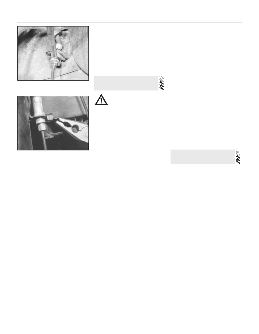
Repeat the procedure at the other end of the
pipe, then release the pipe by pulling out the
clips attaching it to the body (see
illustrations). Where the union nuts are
exposed to the full force of the weather, they
can sometimes be quite tight. If an open-
ended spanner is used, burring of the flats on
the nuts is not uncommon, and for this
reason, it is preferable to use a split ring
(brake) spanner, which will engage all the
flats. If such a spanner is not available, self-
locking grips may be used as a last resort;
these may well damage the nuts, but if the
pipe is to be renewed, this does not matter.
7 To further minimise the loss of fluid when
disconnecting a flexible brake line from a rigid
pipe, clamp the hose as near as possible to
the pipe to be detached, using a brake hose
clamp or a pair of self-locking grips with
protected jaws.
8 To remove a flexible hose, first clean the
ends of the hose and the surrounding area,
then unscrew the union nuts from the hose
ends. Recover the spring clip, and withdraw
the hose from the serrated mounting in the
support bracket. Where applicable, unscrew
the hose from the caliper.
9 Brake pipes supplied with flared ends and
union nuts can be obtained individually or in
sets from Ford dealers or accessory shops.
The pipe is then bent to shape, using the old
pipe as a guide, and is ready for fitting. Be
careful not to kink or crimp the pipe when
bending it; ideally, a proper pipe-bending tool
should be used.
Refitting
10 Refitting of the pipes and hoses is a
reversal of removal. Make sure that all brake
pipes are securely supported in their clips,
and ensure that the hoses are not kinked.
Check also that the hoses are clear of all
suspension components and underbody
fittings, and will remain clear during
movement of the suspension and steering.
11 On completion, bleed the brake hydraulic
system as described in Section 15.
Warning: Brake fluid is
poisonous. Take care to keep it
off bare skin, and in particular
not to get splashes in your eyes.
The fluid also attacks paintwork - wash off
spillages immediately with cold water.
1 If the master cylinder has been
disconnected and reconnected, then the
complete system (both circuits) must be bled
of air. If a component of one circuit has been
disturbed, then only that particular circuit
need be bled.
2 Bleeding should commence on one front
brake, followed by the diagonally-opposite
rear brake. The remaining front brake should
then be bled, followed by its diagonally-
opposite rear brake.
3 There are a variety of do-it-yourself “one-
man” brake bleeding kits available from motor
accessory shops, and it is recommended that
one of these kits be used wherever possible,
as they greatly simplify the brake bleeding
operation. Follow the kit manufacturer’s
manuals in conjunction with the following
procedure. If a pressure-bleeding kit is
obtained, then it will not be necessary to
depress the brake pedal in the following
procedure.
4 During the bleeding operation, do not allow
the brake fluid level in the reservoir to drop
below the minimum mark. If the level is
allowed to fall so far that air is drawn in, the
whole procedure will have to be started again
from scratch. Only use new fluid for topping-
up, preferably from a freshly-opened
container.
Never re-use fluid bled from the
system.
5 Before starting, check that all rigid pipes
and flexible hoses are in good condition, and
that all hydraulic unions are tight. Take great
care not to allow hydraulic fluid to come into
contact with the vehicle paintwork, otherwise
the finish will be seriously damaged. Wash off
any spilt fluid immediately with cold water.
6 If a brake bleeding kit is not being used,
gather together a clean jar, a length of plastic
or rubber tubing which is a tight fit over the
bleed screw, and a new can of the specified
brake fluid (see Chapter 1 Specifications). The
help of an assistant will also be required.
7 Clean the area around the bleed screw on
the front brake unit to be bled (it is important
that no dirt be allowed to enter the hydraulic
system), and remove the dust cap. Connect
one end of the tubing to the bleed screw, and
immerse the other end in the jar, which should
be filled with sufficient brake fluid to keep the
end of the tube submerged.
8 Open the bleed screw by one or two turns,
and have the assistant depress the brake
pedal to the floor. Tighten the bleed screw at
the end of the downstroke, then have the
assistant release the pedal. Continue this
procedure until clean brake fluid, free from air
bubbles, can be seen flowing into the jar.
Finally tighten the bleed screw with the pedal
in the fully-depressed position.
9 Remove the tube, and refit the dust cap.
Top-up the master cylinder reservoir if
necessary, then repeat the procedure on the
diagonally-opposite rear brake.
10 Repeat the procedure on the remaining
circuit, starting with the front brake, and
followed by the diagonally-opposite rear
brake.
11 Check the feel of the brake pedal - it
should be firm. If it is spongy, there is still
some air in the system, and the bleeding
procedure should be repeated.
12 When bleeding is complete, top-up the
master cylinder reservoir and refit the cap.
Testing
1 To test the operation of the servo unit,
depress the footbrake four or five times to
dissipate the vacuum, then start the engine
while keeping the footbrake depressed. As
the engine starts, there should be a noticeable
“give” in the brake pedal as vacuum builds
up. Allow the engine to run for at least two
minutes, and then switch it off. If the brake
pedal is now depressed again, it should be
possible to hear a hiss from the servo when
the pedal is depressed. After four or five
applications, no further hissing should be
heard, and the pedal should feel harder.
2 Before assuming that a problem exists in
the servo unit itself, inspect the non-return
valve as described in the next Section.
Removal
3 Refer to Section 11 and remove the master
cylinder.
4 Disconnect the vacuum hose adaptor at the
servo unit by pulling it free from the rubber
grommet. If it is reluctant to move, prise it
free, using a screwdriver with its blade
inserted under the flange.
5 Unscrew the four nuts securing the servo
unit to the mounting brackets on the bulkhead
in the engine compartment.
6 On right-hand drive models, withdraw the
servo unit so that its studs are just clear of the
brackets. Have an assistant hold the brake
pedal depressed, then extract the spring clip
16 Vacuum servo unit -
testing, removal and refitting
15 Hydraulic system - bleeding
9•12 Braking system
14.6A Unscrewing a brake pipe union nut
using a split ring spanner
14.6B Pulling out a brake pipe mounting
clip